Senzori Presiune Engl
Senzori Presiune Engl
Senzori Presiune Engl

You also want an ePaper? Increase the reach of your titles
YUMPU automatically turns print PDFs into web optimized ePapers that Google loves.
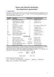
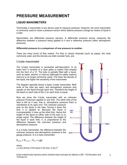
PRESSURE MEASUREMENT<br />
LIQUID MANOMETERS<br />
Technically a manometer is any device used to measure pressure. However, the word manometer<br />
is commonly used to mean a pressure sensor which detects pressure change by means of liquid in<br />
a tube.<br />
Manometers are differential pressure sensors. A differential pressure sensor measures the<br />
difference between a pressure being applied to it and a reference pressure (often atmospheric<br />
pressure).<br />
Differential pressure is a comparison of one pressure to another.<br />
There are many forms of flow meters. For flow in closed channels (such as pipes), the most<br />
commonly used, and the devices we shall consider here, are:<br />
U-tube manometer<br />
The U-tube manometer is somewhat self-descriptive. In its<br />
basic form it consists of a clear glass or plastic tube shaped<br />
into the form of a 'U'. The tube is partially filled with a liquid,<br />
such as water, alcohol, or mercury (although for safety reasons<br />
mercury is no longer commonly used). The lower the density of<br />
the liquid, the higher the sensitivity of the manometer.<br />
The diagram opposite shows a basic U-tube manometer. Both<br />
ends of the tube are open, and atmospheric pressure acts<br />
equally on the liquid through each end. Therefore the height of<br />
the liquid on each side of the U (in each limb) is equal.<br />
Now we show the U-tube manometer with an unknown<br />
pressure Punknown applied to one limb. The other limb of the<br />
tube is left as it was, that is, atmospheric pressure Patm is<br />
maintained at its open end. The unknown pressure<br />
acts on the liquid in the tube, forcing it down the<br />
limb it is applied to. Because the liquid is<br />
incompressible, it rises up the other limb. Hence the<br />
height of the liquid on either side of the tube is no<br />
longer equal. The difference between the height of<br />
the liquid in each limb, h, is proportional to the<br />
difference between the unknown pressure and<br />
atmospheric pressure.<br />
In a U-tube manometer, the difference between the<br />
unknown pressure and atmospheric pressure is the<br />
gauge pressure. In a U-tube manometer,<br />
Pgauge = Punknown - Patm = ρgh<br />
where,<br />
ρ is the density of the liquid in the tube, in kg m -3<br />
Acest material este reprodus pentru studenti dupa manualul de utilizare a SIS - TQ Education and<br />
Training Ltd.<br />
1
g is the acceleration due to gravity, that is, 9.81 m.s -2<br />
h is difference between the heights of the liquid in each limb, in m<br />
If we know atmospheric pressure, or can accept the errors which occur using the standard value,<br />
then we can find Punknown by rearranging the equation,<br />
Punknown = Patm + ρgh<br />
The accuracy of U-tube manometers is largely dependant on the skill of the reader in judging the<br />
difference in height of the liquids in each limb. So that this can be made easier and the height<br />
difference h can be read from one limb, a half-scale is sometimes used. Because the increase in<br />
the fluid level in one limb is directly proportional to the decrease in level in the other limb, every 1<br />
mm change in level in one limb represents a change in h of 2 mm. A half-scale will have, say,<br />
every 5 mm labelled on one limb as 10 mm, representing the change in h.<br />
The U-tube manometer is not in wide use in industry, although it is sometimes used to calibrate<br />
other instruments. It is mainly used in<br />
laboratories for experimental work and<br />
demonstration purposes. It can be used<br />
to measure the pressure of flowing<br />
liquids as well as gases, but cannot be<br />
used remotely. If pressures fluctuate<br />
rapidly its response may be poor and<br />
reading difficult.<br />
This picture shows manometers used in<br />
a piece of experimental apparatus for<br />
measuring flow of a liquid. As we shall<br />
see in the section on flow, the pressure<br />
of a liquid in a pipe relates to its flow<br />
rate. Here, a multi-limb manometer is<br />
used, which is effectively a series of<br />
inverted U-tube manometers.<br />
Inclined Tube Manometer<br />
The inclined tube manometer is a differential<br />
pressure sensor more sensitive than the U-tube<br />
manometer. Hence it is more suitable for use with<br />
smaller pressure measurements or where greater<br />
accuracy is required. This diagram shows its basic<br />
design.<br />
One limb of the inclined tube manometer forms into<br />
a reservoir. The other limb of the manometer is<br />
inclined at a known angle θ. The inclined limb is made from a transparent material such as glass or<br />
plastic. The reservoir is usually made of plastic, but does not need to be transparent.<br />
The surface area of the fluid in the reservoir A1 is much larger than the<br />
surface area of the fluid in the inclined limb A2. Both limbs are open ended<br />
and so subject to atmospheric pressure. If an unknown pressure Punknown<br />
is applied to the reservoir limb, the change in height h1 will be relatively<br />
small compared to the change in height in the inclined limb h2.<br />
Acest material este reprodus pentru studenti dupa manualul de utilizare a SIS - TQ Education and<br />
Training Ltd.<br />
2
The gauge pressure is given by the equation<br />
Pgauge = Punknown - Patm = ρgd(A2/A1+sinθ)<br />
where,<br />
r is the density of the liquid in the tube, in kg m –3<br />
g is the acceleration due to gravity, that is, 9.81 m.s –2<br />
d is the distance the liquid has moved along the inclined limb, in m<br />
A2 is the cross-sectional area of the reservoir, in m²<br />
A1 is the cross-sectional area of the liquid in the inclined limb<br />
θ is the angle of the inclined limb from the horizontal.<br />
Because A1 is much larger than A2, the ratio A1/A2 can be considered negligible. Therefore<br />
Pgauge = Punknown - Patm = ρgdsinθ<br />
If we know the atmospheric pressure, or can accept the errors which occur using the standard<br />
value, then we can find Punknown by rearranging the equation,<br />
Punknown = Patm + ρgdsinθ<br />
This picture shows a multi-limb inclined tube manometer used with<br />
experimental apparatus investigating air flow. Notice that the angle<br />
of inclination can be varied. This allows adjustment of the range<br />
and sensitivity to suit the pressure being measured.<br />
The accuracy of inclined tube manometers relies less on the skill<br />
of the reader than U-tube manometers. They are more sensitive,<br />
but unless the inclined limb is relatively long they cannot be used<br />
over as wide a range of pressures.<br />
Inclined tube manometers are used where higher sensitivity than a U-tube manometer is required.<br />
It cannot be read remotely, and it is usually used with gases.<br />
ELASTIC PRESSURE SENSORS<br />
Elastic pressure sensors are so called because something flexes, stretches, or temporarily<br />
deforms when a pressure is applied.<br />
Elastic pressure sensors initially convert pressure into a displacement.<br />
This allows displacement sensors to be used to condition the output signal from the pressure<br />
sensor. Some pressure sensors are referred to by the method they use to measure this<br />
displacement, such as piezoelectric and capacitive pressure sensors. Where electronic<br />
displacement sensors are used, the method of detecting pressure change is usually by means of a<br />
diaphragm. Elastic pressure sensors measure pressure differentially.<br />
The elastic pressure sensors we will be studying are:<br />
Bourdon tube pressure gauge<br />
The Bourdon tube pressure gauge, named after Eugène Bourdon, is<br />
probably the most popular pressure sensor.<br />
Acest material este reprodus pentru studenti dupa manualul de utilizare a SIS - TQ Education and<br />
Training Ltd.<br />
3
Basic Bourdon tubes are made from metal alloys such as stainless steel or brass. They consist of<br />
a tube of elliptical or oval cross-section, sealed at one end. There are various shapes of Bourdon<br />
tube, including helical, spiral and twisted. A common design is the C-shape, as shown to the right.<br />
Here the tube is at atmospheric pressure. When<br />
increased pressure is applied to the open end, it<br />
deflects outwards (tries to straighten) in proportion to<br />
the pressure inside the tube (the outside of the tube<br />
remains at atmospheric pressure).<br />
As the pressure is decreased, the tube starts to<br />
return to its atmospheric pressure position. The<br />
amount by which the tube moves in relation to the<br />
pressure applied to it depends on factors including its<br />
material, shape, thickness, and length. Compared to<br />
other elastic pressure sensors the deflection<br />
produced by Bourdon tubes is large.<br />
The Bourdon tube pressure gauge, shown here,<br />
consists of a Bourdon tube connected to a pointer. The pointer moves over a calibrated scale.<br />
When pressure is applied, the movement of the tube is fairly small, so to increase the movement of<br />
the pointer it is mechanically amplified. This is<br />
usually by a connecting mechanism consisting of a<br />
lever, quadrant and pinion arrangement.<br />
Bourdon tubes need some form of compensation<br />
for temperature, as temperature changes affect<br />
their accuracy. For remote sensing, the<br />
displacement of the Bourdon tube caused by<br />
pressure changes can be detected by a suitable<br />
displacement sensor.<br />
Here we show an LVDT connected to a Bourdon<br />
tube. This converts the displacement at the end of<br />
the tube into an electrical signal. This signal can<br />
then be displayed or recorded on an electrical<br />
device calibrated in terms of pressure.<br />
Some designs of Bourdon tube pressure gauge tend to be fairly inexpensive because they are<br />
mass produced (which reduces costs). They are suitable for use with both liquids and gases, are<br />
used in a wide variety of applications, both industrial and<br />
domestic. Applications range from tyre pressure gauges,<br />
measuring the pressure in pneumatically controlled tools<br />
and machines, to pipeline pressure in chemical plants.<br />
Bellows<br />
Bellows are differential pressure sensing devices mainly<br />
used in low pressure ranges of about 0 to 1000 pascals.<br />
Here we show a set of metallic bellows, held inside a<br />
protective casing. The bellows are made of a thin copper<br />
alloy tube pressed into a corrugated shape. This is<br />
sealed at one end, with a small hole at the other end.<br />
When pressure is applied via the hole, the bellows<br />
expand a distance d. This displacement can be calibrated<br />
Acest material este reprodus pentru studenti dupa manualul de utilizare a SIS - TQ Education and<br />
Training Ltd.<br />
4
in terms of pressure.<br />
The pressure applied to the bellows Punknown is given by the equation<br />
Punknown = (d/A)λ<br />
where,<br />
d is the distance moved by the bellows in m<br />
A is the cross sectional area of the bellows in m²<br />
λ is the stiffness of the bellows in N.m –1<br />
Here is a single chamber 'bellow'. It consists of two circular<br />
metal diaphragms connected back to back. These devices,<br />
commonly referred to as capsules, give smaller displacements<br />
than multi-chamber bellows.<br />
Bellows usually produce small displacements. These need to be<br />
amplified, and displacement sensors such as LVDTs and<br />
potentiometers are often used to convert the displacement into<br />
an electrical signal.<br />
Here is a bellows sensor used with an LVDT.<br />
The LVDT produces an electrical output signal<br />
directly related to the displacement input<br />
signal. This can then be displayed or recorded<br />
on a device calibrated in terms of pressure.<br />
Bellows should not be used in an environment<br />
where they may be subjected to vibration or<br />
shock. Their accuracy is also affected by<br />
temperature changes.<br />
An example of the use of bellows is in control<br />
applications, for closing valves in a pipe when a critical pressure is reached.<br />
Capacitive pressure sensors<br />
Capacitive pressure sensors use the electrical property<br />
of capacitance to measure the displacement of a<br />
diaphragm. The diaphragm is an elastic pressure<br />
sensor displaced in proportion to changes in pressure.<br />
It acts as one plate of a capacitor.<br />
The diaphragm consists of a thin plate of metal alloy,<br />
such as stainless steel or brass. It is circular and fixed<br />
continuously around its edges to a cylinder. This<br />
diagram shows how it displaces when a pressure is<br />
applied to it. It is a differential pressure sensor,<br />
because it is subject to atmospheric pressure. The<br />
amount by which the diaphragm moves with respect to the unknown pressure applied to it depends<br />
on its shape and construction, size, thickness, and material. Therefore the precise relationship<br />
between pressure and displacement varies with each design. However, the displacement is small,<br />
rarely more than a few millimetres, often fractions of a millimetre. Because of this, these devices<br />
are often individually calibrated (against an accurate inclined tube manometer, for example).<br />
Acest material este reprodus pentru studenti dupa manualul de utilizare a SIS - TQ Education and<br />
Training Ltd.<br />
5
Because the displacement of the diaphragm is small, a displacement sensing device with high<br />
resolution, sensitivity and accuracy is required. Also, a non-contact device is required as any<br />
mechanical resistance will reduce the displacement even more. Using the diaphragm as one plate<br />
of a capacitor is a non-contact displacement<br />
sensing method, providing an electrical output with<br />
infinite resolution particularly suited to small<br />
displacements.<br />
This diagram shows a diaphragm and capacitor<br />
combination. One plate of the capacitor is fixed, the<br />
other plate is the diaphragm. The dielectric is<br />
usually air. Notice that it does not use the variable<br />
area technique like the capacitive displacement<br />
sensor. Instead, the distance between the plates is<br />
varied. When there is a change in pressure, the<br />
diaphragm deflects in proportion to it, and this<br />
causes the distance d between the plates of the<br />
capacitor to change. The capacitance c of the<br />
capacitor is (approximately) inversely proportional<br />
to the distance d between the plates. That is, c ∝ 1/d<br />
An electrical signal is connected to the two plates of the capacitor. The<br />
change in value of the capacitance causes this electrical signal to vary.<br />
This is then conditioned and displayed on a device calibrated in terms of<br />
pressure.<br />
There are techniques other than change in capacitance used to measure<br />
the displacement of a diaphragm. For example, another design of<br />
pressure sensor uses a diaphragm made from silicon. Semiconductor<br />
strain gauges are diffused into the diaphragm. They are arranged in a<br />
form similar to the Wheatstone bridge. A stable electrical output is produced, and the arrangement<br />
of the strain gauges compensates for temperature changes. However, these types of pressure<br />
sensor are relatively expensive.<br />
Because of the sensitivity of diaphragm based pressure sensors, they are used to measure small<br />
changes in pressure. An example application is small changes in pressure in liquid or gas pipelines<br />
so that the flow rate can be measured. See the flow section for how this achieved<br />
Piezoelectric pressure sensor<br />
This diagram shows the principle of a piezoelectric pressure sensor. These sensors are similar to<br />
capacitive pressure sensors in that they detect pressure changes by the displacement of a thin<br />
metal or semiconductor diaphragm. In a pressure sensor<br />
using the piezoelectric effect, the diaphragm causes a strain<br />
on the piezoelectric crystal when flexing due to pressure<br />
changes. The electric charges of opposite polarity appearing<br />
on the faces of the crystal are proportional to this strain.<br />
The piezoelectric crystal is usually quartz. This type of<br />
pressure sensor often incorporates signal conditioning<br />
circuitry in a sealed unit, using integrated circuit technology.<br />
Piezoelectric pressure sensors operate at high temperatures<br />
and can be made small in size. Their main advantage is that<br />
they have a fast response and fairly wide operating range.<br />
Hence they can be used in applications such as measuring<br />
Acest material este reprodus pentru studenti dupa manualul de utilizare a SIS - TQ Education and<br />
Training Ltd.<br />
6
the pressure in a gun barrel when it is fired. They have very high sensitivity and also good<br />
accuracy, repeatability and low hysteresis.<br />
Piezoresistive and strain gauge pressure sensors<br />
A pressure sensor similar to the piezoelectric<br />
pressure sensor is the piezoresistive pressure<br />
sensor. These devices use silicon<br />
diaphragms, which form part of a<br />
semiconductor integrated circuit chip.<br />
Piezoresistivity is a strain dependent<br />
resistivity in single crystal<br />
semiconductors.<br />
Four piezoresistors on the diaphragm form a<br />
Wheatstone bridge as shown here.<br />
When pressure is applied to the<br />
diaphragm it causes a strain in the<br />
resistors. The resistance of the<br />
piezoresistors changes in proportion<br />
to this strain, and hence the change<br />
in pressure.<br />
A typical specification of a<br />
piezoresistive pressure transducer<br />
can be found in the [reference section].<br />
The range of piezoresistive pressure sensors is normally low, typically at a maximum of about 0 to<br />
200 kPa. They are used where good repeatability, high accuracy, low<br />
hysteresis and long term stability are required. A typical application is<br />
in sensing the pressure at the bottom of a water tank. This pressure is<br />
directly related to the depth of water, and so the pressure sensor<br />
forms part of a level measurement system.<br />
For measuring higher pressure ranges, instead of piezoresistors,<br />
bonded resistance strain gauges may be used. These are based on a<br />
similar principle to the piezoresistive strain gauge, in that the resistors<br />
are bonded to a diaphragm and formed into a Wheatstone bridge.<br />
They can measure pressures up to about 25000 kPa.<br />
BAROMETERS<br />
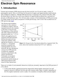
A barometer is a pressure sensor specifically used to measure<br />
atmospheric pressure. Because of this they have to be sensitive, and<br />
measure absolute pressure. They are mainly used for meteorological<br />
purposes. High atmospheric pressure is usually associated with fine<br />
weather while low pressure usually predicts poor weather.<br />
Barometers have existed for many years, and there are two basic<br />
types.<br />
Acest material este reprodus pentru studenti dupa manualul de utilizare a SIS - TQ Education and<br />
Training Ltd.<br />
7
Liquid in glass barometer<br />
This barometer is a type of liquid manometer. It consists of a thin glass tube containing a liquid.<br />
The liquid is usually mercury to keep the length of the barometer as small as possible.<br />
This diagram shows the basic design of a liquid in glass barometer. It consists of a U-shaped<br />
manometer fixed to a backing plate. One limb forms a reservoir, and is open to atmospheric<br />
pressure via a small hole. The other limb is a thin tube, containing a volume of liquid small in<br />
comparison to that contained in the reservoir. Like the inclined tube manometer, this allows the<br />
pressure to be read against a scale on one limb. The end of this limb contains a vacuum and is<br />
sealed.<br />
A pure vacuum is a space totally devoid of any matter, which therefore has no pressure. On<br />
Earth a pure vacuum is impossible to achieve. However, the term vacuum is applied to<br />
something having a pressure lower than atmospheric pressure.<br />
It is the vacuum which allows the barometer to measure<br />
absolute pressure. It is still measuring the difference in<br />
pressure between the two limbs. However, the pressure<br />
produced by the vacuum is lower than the local air<br />
pressure, and constant. Therefore, the pressure acting<br />
on the limb containing the vacuum can be considered<br />
negligible. The only significant pressure acting on the<br />
liquid in the barometer is the atmospheric pressure.<br />
Hence the height of the liquid in the tube is proportional<br />
to atmospheric pressure.<br />
The level of the reservoir may be adjusted on some liquid<br />
in glass barometers. This allows it to be matched to the<br />
zero of the scale before readings are taken thus<br />
improving accuracy.<br />
There are several designs of liquid in glass barometer.<br />
They are accurate but can be rather cumbersome. They<br />
also tend to be fragile, and their accuracy is significantly affected by temperature variations. They<br />
are usually in a fixed position and are often used for calibration of other pressure sensors or as a<br />
datum in laboratories<br />
Aneroid barometer<br />
The word aneroid simply means something<br />
which does not contain liquid, and so<br />
distinguishes this type of barometer from the<br />
liquid in glass type.<br />
The aneroid barometer, shown here, senses<br />
atmospheric pressure changes by means of a<br />
sealed metal capsule. One or two faces of the<br />
capsule are diaphragms. The capsule contains<br />
a partial vacuum. Because the pressure inside<br />
the capsule is lower than atmospheric pressure<br />
and constant, it is sensitive to changes in<br />
atmospheric pressure. If atmospheric pressure<br />
increases, the diaphragms move and the<br />
capsule flattens. If atmospheric pressure rises, the capsule expands. This displacement is detected<br />
Acest material este reprodus pentru studenti dupa manualul de utilizare a SIS - TQ Education and<br />
Training Ltd.<br />
8
y a bar pressed on to the capsule by a strong spring. This is mechanically amplified by gears and<br />
levers and transmitted to a pointer on a calibrated scale.<br />
The aneroid barometer is simpler to read and takes up less space than the liquid in glass<br />
barometer. It is not affected by temperature changes as significantly, but is less accurate mainly<br />
because of its mechanical parts. In fact, aneroid barometers are usually calibrated against liquid in<br />
glass barometers.<br />
Aneroid barometers are commonly used for domestic purposes. They are likely to be calibrated in<br />
non-SI units, such as millimetres of mercury or bar. Some versions are calibrated with respect to<br />
likely weather conditions!<br />
If electronic measurement is required, the movement of the diaphragm can be detected in terms of<br />
capacitance as discussed earlier in this section. This increases accuracy and sensitivity. Because<br />
atmospheric pressure changes with altitude, capacitive aneroid barometers sometimes form the<br />
basis of altimeters in aircraft.<br />
Acest material este reprodus pentru studenti dupa manualul de utilizare a SIS - TQ Education and<br />
Training Ltd.<br />
9