LCD Information
LCD Information
LCD Information

Create successful ePaper yourself
Turn your PDF publications into a flip-book with our unique Google optimized e-Paper software.
<strong>LCD</strong> Interfacing with Microcontrollers tutorial<br />
►Introduction<br />
The most commonly used Character based <strong>LCD</strong>s are based on Hitachi's HD44780 controller or other which are compatible with HD44580. In this tutorial, we will<br />
discuss about character based <strong>LCD</strong>s, their interfacing with various microcontrollers, various interfaces (8-bit/4-bit), programming, special stuff and tricks you can<br />
do with these simple looking <strong>LCD</strong>s which can give a new look to your application.<br />
For Specs and technical information HD44780 controller Click Here<br />
►Pin Description<br />
The most commonly used <strong>LCD</strong>s found in the market today are 1 Line, 2 Line or 4 Line <strong>LCD</strong>s which have only 1 controller and support at most of 80 characters,<br />
whereas <strong>LCD</strong>s supporting more than 80 characters make use of 2 HD44780 controllers.<br />
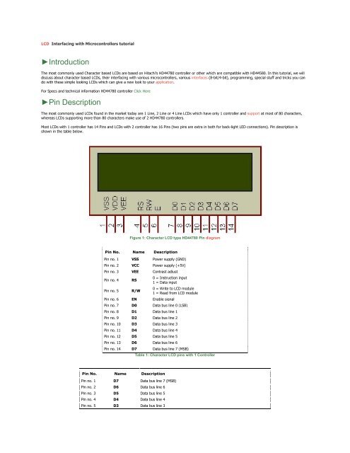
Most <strong>LCD</strong>s with 1 controller has 14 Pins and <strong>LCD</strong>s with 2 controller has 16 Pins (two pins are extra in both for back-light LED connections). Pin description is<br />
shown in the table below.<br />
Figure 1: Character <strong>LCD</strong> type HD44780 Pin diagram<br />
Pin No. Name Description<br />
Pin no. 1 VSS Power supply (GND)<br />
Pin no. 2 VCC Power supply (+5V)<br />
Pin no. 3 VEE Contrast adjust<br />
Pin no. 4 RS<br />
Pin no. 5 R/W<br />
0 = Instruction input<br />
1 = Data input<br />
Pin no. 6 EN Enable signal<br />
0 = Write to <strong>LCD</strong> module<br />
1 = Read from <strong>LCD</strong> module<br />
Pin no. 7 D0 Data bus line 0 (LSB)<br />
Pin no. 8 D1 Data bus line 1<br />
Pin no. 9 D2 Data bus line 2<br />
Pin no. 10 D3 Data bus line 3<br />
Pin no. 11 D4 Data bus line 4<br />
Pin no. 12 D5 Data bus line 5<br />
Pin no. 13 D6 Data bus line 6<br />
Pin no. 14 D7 Data bus line 7 (MSB)<br />
Pin No. Name Description<br />
Table 1: Character <strong>LCD</strong> pins with 1 Controller<br />
Pin no. 1 D7 Data bus line 7 (MSB)<br />
Pin no. 2 D6 Data bus line 6<br />
Pin no. 3 D5 Data bus line 5<br />
Pin no. 4 D4 Data bus line 4<br />
Pin no. 5 D3 Data bus line 3
Pin no. 6 D2 Data bus line 2<br />
Pin no. 7 D1 Data bus line 1<br />
Pin no. 8 D0 Data bus line 0 (LSB)<br />
Pin no. 9 EN1 Enable signal for row 0 and 1 (1 st controller)<br />
Pin no. 10 R/W<br />
Pin no. 11 RS<br />
0 = Write to <strong>LCD</strong> module<br />
1 = Read from <strong>LCD</strong> module<br />
0 = Instruction input<br />
1 = Data input<br />
Pin no. 12 VEE Contrast adjust<br />
Pin no. 13 VSS Power supply (GND)<br />
Pin no. 14 VCC Power supply (+5V)<br />
Pin no. 15 EN2 Enable signal for row 2 and 3 (2 nd controller)<br />
Pin no. 16 NC Not Connected<br />
Table 2: Character <strong>LCD</strong> pins with 2 Controller<br />
Usually these days you will find single controller <strong>LCD</strong> modules are used more in the market. So in the tutorial we will discuss more about the single controller <strong>LCD</strong>,<br />
the operation and everything else is same for the double controller too. Lets take a look at the basic information which is there in every <strong>LCD</strong>.<br />
►DDRAM - Display Data RAM<br />
Display data RAM (DDRAM) stores display data represented in 8-bit character codes. Its extended capacity is 80 X 8 bits, or 80 characters. The area in display<br />
data RAM (DDRAM) that is not used for display can be used as general data RAM. So whatever you send on the DDRAM is actually displayed on the <strong>LCD</strong>. For <strong>LCD</strong>s<br />
like 1x16, only 16 characters are visible, so whatever you write after 16 chars is written in DDRAM but is not visible to the user.<br />
Figures below will show you the DDRAM addresses of 1 Line, 2 Line and 4 Line <strong>LCD</strong>s.<br />
Figure 2: DDRAM Address for 1 Line <strong>LCD</strong><br />
Figure 3: DDRAM Address for 2 Line <strong>LCD</strong><br />
Figure 4: DDRAM Address for 4 Line <strong>LCD</strong><br />
►CGROM - Character Generator ROM<br />
Now you might be thinking that when you send an ascii value to DDRAM, how the character is displayed on <strong>LCD</strong>? so the answer is CGROM. The character<br />
generator ROM generates 5 x 8 dot or 5 x 10 dot character patterns from 8-bit character codes (see Figure 5 and Figure 6 for more details). It can generate 208 5<br />
x 8 dot character patterns and 32 5 x 10 dot character patterns. User defined character patterns are also available by mask-programmed ROM.
Figure 5: <strong>LCD</strong> characters code map for 5x8 dots
Figure 6: <strong>LCD</strong> characters code map for 5x10 dots<br />
As you can see in both the code maps, the character code from 0x00 to 0x07 is occupied by the CGRAM characters or the user defined characters. If user want to<br />
display the fourth custom character then the code to display it is 0x03 i.e. when user send 0x03 code to the <strong>LCD</strong> DDRAM then the fourth user created character or<br />
pattern will be displayed on the <strong>LCD</strong>.<br />
►CGRAM - Character Generator RAM<br />
As clear from the name, CGRAM area is used to create custom characters in <strong>LCD</strong>. In the character generator RAM, the user can rewrite character patterns by<br />
program. For 5 x 8 dots, eight character patterns can be written, and for 5 x 10 dots, four character patterns can be written. Later in this tutorial i will explain how<br />
to use CGRAM area to make custom character and also making animations to give nice effects to your application.<br />
►BF - Busy Flag<br />
Busy Flag is an status indicator flag for <strong>LCD</strong>. When we send a command or data to the <strong>LCD</strong> for processing, this flag is set (i.e BF =1) and as soon as the<br />
instruction is executed successfully this flag is cleared (BF = 0). This is helpful in producing and exact amount of delay. for the <strong>LCD</strong> processing.<br />
To read Busy Flag, the condition RS = 0 and R/W = 1 must be met and The MSB of the <strong>LCD</strong> data bus (D7) act as busy flag. When BF = 1 means <strong>LCD</strong> is busy and<br />
will not accept next command or data and BF = 0 means <strong>LCD</strong> is ready for the next command or data to process.<br />
►Instruction Register (IR) and Data Register (DR)<br />
There are two 8-bit registers in HD44780 controller Instruction and Data register. Instruction register corresponds to the register where you send commands to<br />
<strong>LCD</strong> e.g <strong>LCD</strong> shift command, <strong>LCD</strong> clear, <strong>LCD</strong> address etc. and Data register is used for storing data which is to be displayed on <strong>LCD</strong>. when send the enable signal<br />
of the <strong>LCD</strong> is asserted, the data on the pins is latched in to the data register and data is then moved automatically to the DDRAM and hence is displayed on the<br />
<strong>LCD</strong>.
Data Register is not only used for sending data to DDRAM but also for CGRAM, the address where you want to send the data, is decided by the instruction you<br />
send to <strong>LCD</strong>. We will discuss more on <strong>LCD</strong> instruction set further in this tutorial.<br />
►Commands and Instruction set<br />
Only the instruction register (IR) and the data register (DR) of the <strong>LCD</strong> can be controlled by the MCU. Before starting the internal operation of the <strong>LCD</strong>, control<br />
information is temporarily stored into these registers to allow interfacing with various MCUs, which operate at different speeds, or various peripheral control<br />
devices. The internal operation of the <strong>LCD</strong> is determined by signals sent from the MCU. These signals, which include register selection signal (RS), read/write<br />
signal (R/W), and the data bus (DB0 to DB7), make up the <strong>LCD</strong> instructions (Table 3). There are four categories of instructions that:<br />
Designate <strong>LCD</strong> functions, such as display format, data length, etc.<br />
Set internal RAM addresses<br />
Perform data transfer with internal RAM<br />
Perform miscellaneous functions<br />
Table 3: Command and Instruction set for <strong>LCD</strong> type HD44780<br />
Although looking at the table you can make your own commands and test them. Below is a brief list of useful commands which are used frequently while working<br />
on the <strong>LCD</strong>.
No. Instruction Hex Decimal<br />
1 Function Set: 8-bit, 1 Line, 5x7 Dots 0x30 48<br />
2 Function Set: 8-bit, 2 Line, 5x7 Dots 0x38 56<br />
3 Function Set: 4-bit, 1 Line, 5x7 Dots 0x20 32<br />
4 Function Set: 4-bit, 2 Line, 5x7 Dots 0x28 40<br />
5 Entry Mode 0x06 6<br />
6<br />
Display off Cursor off<br />
(clearing display without clearing DDRAM content)<br />
0x08 8<br />
7 Display on Cursor on 0x0E 14<br />
8 Display on Cursor off 0x0C 12<br />
9 Display on Cursor blinking 0x0F 15<br />
10 Shift entire display left 0x18 24<br />
12 Shift entire display right 0x1C 30<br />
13 Move cursor left by one character 0x10 16<br />
14 Move cursor right by one character 0x14 20<br />
15 Clear Display (also clear DDRAM content) 0x01 1<br />
16 Set DDRAM address or coursor position on display 0x80+add* 128+add*<br />
17 Set CGRAM address or set pointer to CGRAM location 0x40+add** 64+add**<br />
* DDRAM address given in <strong>LCD</strong> basics section see Figure 2,3,4<br />
** CGRAM address from 0x00 to 0x3F, 0x00 to 0x07 for char1 and so on..<br />
Table 4: Frequently used commands and instructions for <strong>LCD</strong><br />
The table above will help you while writing programs for <strong>LCD</strong>. But after you are done testing with the table 4, i recommend you to use table 3 to get more grip on<br />
working with <strong>LCD</strong> and trying your own commands. In the next section of the tutorial we will see the initialization with some of the coding examples in C as well as<br />
assembly.<br />
►<strong>LCD</strong> Initialization<br />
Before using the <strong>LCD</strong> for display purpose, <strong>LCD</strong> has to be initialized either by the internal reset circuit or sending set of commands to initialize the <strong>LCD</strong>. It is the<br />
user who has to decide whether an <strong>LCD</strong> has to be initialized by instructions or by internal reset circuit. we will discuss both ways of initialization one by one.<br />
Initialization by internal Reset Circuit<br />
An internal reset circuit automatically initializes the HD44780U when the power is turned on. The following instructions are executed during the initialization. The<br />
busy flag (BF) is kept in the busy state until the initialization ends (BF = 1). The busy state lasts for 10 ms after VCC rises to 4.5 V.<br />
Display clear<br />
Function set:<br />
DL = 1; 8-bit interface data<br />
N = 0; 1-line display<br />
F = 0; 5 x 8 dot character font<br />
Display on/off control:<br />
D = 0; Display off<br />
C = 0; Cursor off<br />
B = 0; Blinking off<br />
Entry mode set:<br />
I/D = 1; Increment by 1<br />
S = 0; No shift<br />
Note: If the electrical characteristics conditions listed under the table Power Supply Conditions Using Internal Reset Circuit are not met, the internal reset circuit<br />
will not operate normally and will fail to initialize the HD44780U. For such a case, initialization must be performed by the MCU as explained in the section,<br />
Initializing by Instruction.<br />
As mentioned in the Note, there are certain conditions that has to be met, if user want to use initialization by internal reset circuit. These conditions are shown in<br />
the Table 5 below.
Table 5: Power Supply condition for Internal Reset circuit<br />
Figure 7 shows the test condition which are to be met for internal reset circuit to be active.<br />
Figure 7: Internal Power Supply reset<br />
Now the problem with the internal reset circuit is, it is highly dependent on power supply, to meet this critical power supply conditions is not hard but are difficult<br />
to achive when you are making a simple application. So usually the second method i.e. Initialization by instruction is used and is recommended most of the time.<br />
Initialization by instructions<br />
Initializing <strong>LCD</strong> with instructions is really simple. Given below is a flowchart that describes the step to follow, to initialize the <strong>LCD</strong>.
Figure 8: Flow chart for <strong>LCD</strong> initialization<br />
As you can see from the flow chart, the <strong>LCD</strong> is initialized in the following sequence...<br />
1) Send command 0x30 - Using 8-bit interface<br />
2) Delay 20ms<br />
3) Send command 0x30 - 8-bit interface<br />
4) Delay 20ms<br />
5) Send command 0x30 - 8-bit interface<br />
6) Delay 20ms<br />
7) Send Function set - see Table 4 for more information<br />
8) Display Clear command<br />
9) Set entry mode command - explained below<br />
The first 3 commands are usually not required but are recommended when you are using 4-bit interface. So you can program the <strong>LCD</strong> starting from step 7 when<br />
working with 8-bit interface. Function set command depends on what kind of <strong>LCD</strong> you are using and what kind of interface you are using (see Table 4 in <strong>LCD</strong><br />
Command section).<br />
<strong>LCD</strong> Entry mode<br />
From Table 3 in command section, you can see that the two bits decide the entry mode for <strong>LCD</strong>, these bits are:<br />
a) I/D - Increment/Decrement bit<br />
b) S - Display shift.<br />
With these two bits we get four combinations of entry mode which are 0x04,0x05,0x06,0x07 (see table 3 in <strong>LCD</strong> Command section). So we get different results<br />
with these different entry modes. Normally entry mode 0x06 is used which is No shift and auto increment. I recommend you to try all the possible entry modes<br />
and see the results, I am sure you will be surprised.
Programming example for <strong>LCD</strong> Initialization<br />
CODE:<br />
<strong>LCD</strong>_data equ P2 ;<strong>LCD</strong> Data port<br />
<strong>LCD</strong>_D7 equ P2.7 ;<strong>LCD</strong> D7/Busy Flag<br />
<strong>LCD</strong>_rs equ P1.0 ;<strong>LCD</strong> Register Select<br />
<strong>LCD</strong>_rw equ P1.1 ;<strong>LCD</strong> Read/Write<br />
<strong>LCD</strong>_en equ P1.2 ;<strong>LCD</strong> Enable<br />
<strong>LCD</strong>_init:<br />
mov <strong>LCD</strong>_data,#38H ;Function set: 2 Line, 8-bit, 5x7 dots<br />
clr <strong>LCD</strong>_rs ;Selected command register<br />
clr <strong>LCD</strong>_rw ;We are writing in instruction register<br />
setb <strong>LCD</strong>_en ;Enable H->L<br />
clr <strong>LCD</strong>_en<br />
acall <strong>LCD</strong>_busy ;Wait for <strong>LCD</strong> to process the command<br />
mov <strong>LCD</strong>_data,#0FH ;Display on, Curser blinking command<br />
clr <strong>LCD</strong>_rs ;Selected instruction register<br />
clr <strong>LCD</strong>_rw ;We are writing in instruction register<br />
setb <strong>LCD</strong>_en ;Enable H->L<br />
clr <strong>LCD</strong>_en<br />
acall <strong>LCD</strong>_busy ;Wait for <strong>LCD</strong> to process the command<br />
mov <strong>LCD</strong>_data,#01H ;Clear <strong>LCD</strong><br />
clr <strong>LCD</strong>_rs ;Selected command register<br />
clr <strong>LCD</strong>_rw ;We are writing in instruction register<br />
setb <strong>LCD</strong>_en ;Enable H->L<br />
clr <strong>LCD</strong>_en<br />
acall <strong>LCD</strong>_busy ;Wait for <strong>LCD</strong> to process the command<br />
mov <strong>LCD</strong>_data,#06H ;Entry mode, auto increment with no shift<br />
clr <strong>LCD</strong>_rs ;Selected command register<br />
clr <strong>LCD</strong>_rw ;We are writing in instruction register<br />
setb <strong>LCD</strong>_en ;Enable H->L<br />
clr <strong>LCD</strong>_en<br />
acall <strong>LCD</strong>_busy ;Wait for <strong>LCD</strong> to process the command<br />
ret ;Return from routine<br />
Now we can do the same thing in C, I am giving example using Keil C. Similar code can be written for SDCC.<br />
CODE:<br />
#include .<br />
#define <strong>LCD</strong>_data P2<br />
#define <strong>LCD</strong>_D7 P2_7<br />
#define <strong>LCD</strong>_rs P1_0<br />
#define <strong>LCD</strong>_rw P1_1<br />
#define <strong>LCD</strong>_en P1_2<br />
void <strong>LCD</strong>_init()<br />
{<br />
<strong>LCD</strong>_data = 0x38; //Function set: 2 Line, 8-bit, 5x7 dots<br />
<strong>LCD</strong>_rs = 0; //Selected command register<br />
<strong>LCD</strong>_rw = 0; //We are writing in data register<br />
<strong>LCD</strong>_en = 1; //Enable H->L<br />
<strong>LCD</strong>_en = 0;<br />
<strong>LCD</strong>_busy(); //Wait for <strong>LCD</strong> to process the command<br />
<strong>LCD</strong>_data = 0x0F; //Display on, Curser blinking command<br />
<strong>LCD</strong>_rs = 0; //Selected command register<br />
<strong>LCD</strong>_rw = 0; //We are writing in data register
}<br />
<strong>LCD</strong>_en = 1; //Enable H->L<br />
<strong>LCD</strong>_en = 0;<br />
<strong>LCD</strong>_busy(); //Wait for <strong>LCD</strong> to process the command<br />
<strong>LCD</strong>_data = 0x01; //Clear <strong>LCD</strong><br />
<strong>LCD</strong>_rs = 0; //Selected command register<br />
<strong>LCD</strong>_rw = 0; //We are writing in data register<br />
<strong>LCD</strong>_en = 1; //Enable H->L<br />
<strong>LCD</strong>_en = 0;<br />
<strong>LCD</strong>_busy(); //Wait for <strong>LCD</strong> to process the command<br />
<strong>LCD</strong>_data = 0x06; //Entry mode, auto increment with no shift<br />
<strong>LCD</strong>_rs = 0; //Selected command register<br />
<strong>LCD</strong>_rw = 0; //We are writing in data register<br />
<strong>LCD</strong>_en = 1; //Enable H->L<br />
<strong>LCD</strong>_busy();<br />
With the help of the above code, you are able to initialize the <strong>LCD</strong>. Now there is a function/subroutine coming in the code i.e. <strong>LCD</strong>_busy, which is used to put<br />
delay for <strong>LCD</strong> so that there should not be any command or data sent to the <strong>LCD</strong> until it finish executing the command. More on this delay routine is explained in<br />
the next section.<br />
►Reading the busy Flag<br />
As discussed in the previous section, there must be some delay which is needed to be there for <strong>LCD</strong> to successfully process the command or data. So this delay<br />
can be made either with a delay loop of specified time more than that of <strong>LCD</strong> process time or we can read the busy flag, which is recommended. The reason to<br />
use busy flag is that delay produced is almost for the exact amount of time for which <strong>LCD</strong> need to process the time. So is best suited for every application.<br />
Steps to read busy flag<br />
when we send the command, the BF or D7th bit of the <strong>LCD</strong> becomes 1 and as soon as the command is processed the BF = 0. Following are the steps to be kept<br />
in mind while reading the Busy flag.<br />
Select command register<br />
Select read operation<br />
Send enable signal<br />
Read the flag<br />
So following the above steps we can write the code in assembly as below...<br />
CODE:<br />
;Ports used are same as the previous example<br />
<strong>LCD</strong>_busy:<br />
setb <strong>LCD</strong>_D7 ;Make D7th bit of <strong>LCD</strong> data port as i/p<br />
setb <strong>LCD</strong>_en ;Make port pin as o/p<br />
clr <strong>LCD</strong>_rs ;Select command register<br />
setb <strong>LCD</strong>_rw ;we are reading<br />
check:<br />
clr <strong>LCD</strong>_en ;Enable H->L<br />
setb <strong>LCD</strong>_en<br />
jb <strong>LCD</strong>_D7,check ;read busy flag again and again till it becomes<br />
0<br />
ret ;Return from busy routine<br />
The equivalent C code Keil C compiler. Similar code can be written for SDCC.<br />
CODE:
void <strong>LCD</strong>_busy()<br />
{<br />
<strong>LCD</strong>_D7 = 1; //Make D7th bit of <strong>LCD</strong> as i/p<br />
<strong>LCD</strong>_en = 1; //Make port pin as o/p<br />
<strong>LCD</strong>_rs = 0; //Selected command register<br />
<strong>LCD</strong>_rw = 1; //We are reading<br />
while(<strong>LCD</strong>_D7){ //read busy flag again and again till it becomes<br />
0<br />
<strong>LCD</strong>_en = 0; //Enable H->L<br />
<strong>LCD</strong>_en = 1;<br />
}<br />
}<br />
The above routine will provide the necessary delay for the instructions to complete. If you don’t want to read the busy flag you can simply use a delay routine to<br />
provide the a specific amount of delay. A simple delay routine for the <strong>LCD</strong> is given below.<br />
CODE:<br />
<strong>LCD</strong>_busy:<br />
mov r7,#50H<br />
back:<br />
mov r6,#FFH<br />
djnz r6,$<br />
djnz r7,back<br />
ret ;Return from busy routine<br />
CODE:<br />
void <strong>LCD</strong>_busy()<br />
{<br />
unsigned char i,j;<br />
for(i=0;i
<strong>LCD</strong>_command:<br />
mov <strong>LCD</strong>_data,A ;Move the command to <strong>LCD</strong> port<br />
clr <strong>LCD</strong>_rs ;Selected command register<br />
clr <strong>LCD</strong>_rw ;We are writing in instruction register<br />
setb <strong>LCD</strong>_en ;Enable H->L<br />
clr <strong>LCD</strong>_en<br />
acall <strong>LCD</strong>_busy ;Wait for <strong>LCD</strong> to process the command<br />
ret ;Return from busy routine<br />
; Usage of the above routine<br />
; A will carry the command for <strong>LCD</strong><br />
; e.g. we want to send clear <strong>LCD</strong> command<br />
;<br />
; mov a,#01H ;01H is command for clearing <strong>LCD</strong><br />
; acall <strong>LCD</strong>_command ;Send the command<br />
The equivalent C code Keil C compiler. Similar code can be written for SDCC.<br />
CODE:<br />
void <strong>LCD</strong>_command(unsigned char var)<br />
{<br />
<strong>LCD</strong>_data = var; //Function set: 2 Line, 8-bit, 5x7 dots<br />
<strong>LCD</strong>_rs = 0; //Selected command register<br />
<strong>LCD</strong>_rw = 0; //We are writing in instruction register<br />
<strong>LCD</strong>_en = 1; //Enable H->L<br />
<strong>LCD</strong>_en = 0;<br />
<strong>LCD</strong>_busy(); //Wait for <strong>LCD</strong> to process the command<br />
}<br />
// Using the above function is really simple<br />
// var will carry the command for <strong>LCD</strong><br />
// e.g.<br />
//<br />
// <strong>LCD</strong>_command(0x01);<br />
Setting cursor position on <strong>LCD</strong><br />
To set the cursor position on <strong>LCD</strong>, we need to send the DDRAM address...<br />
CODE:<br />
Bit7 6 5 4 3 2 1 0<br />
1 AD6 AD5 AD4 AD3 AD2 AD1 AD0<br />
The seventh bit is always 1, and bit 0 to 7 are DDRAM address (See the introduction section of <strong>LCD</strong>). so if you want to put the cursor on first position the address<br />
will be '0000000B' in binary and 7th bit is 1. so address will be 0x80, so for DDRAM all address starts from 0x80.<br />
For 2 line and 16 character <strong>LCD</strong>. The adress from 0x80 to 0x8F are visible on first line and 0xC0 to 0xCF is visible on second line, rest of the DDRAM area is still<br />
available but is not visible on the <strong>LCD</strong>, if you want to check this thing, then simply put a long sting greater than 16 character and shift the entire display, you will<br />
see all the missing character coming from the back.. this way you can make scrolling line on <strong>LCD</strong> (see more on shifting display in commands section).<br />
Below is an example for setting cursor position on <strong>LCD</strong>.<br />
CODE:<br />
;We are placing the cursor on the 4th position<br />
;so the DDRAM address will be 0x03<br />
;and the command will be 0x80+0x03 = 0x83<br />
mov a,#83H ;load the command<br />
acall <strong>LCD</strong>_command ;send command to <strong>LCD</strong>
CODE:<br />
// to do the same thing is C<br />
// as we done before<br />
<strong>LCD</strong>_command(0x83);<br />
►Sending Data to <strong>LCD</strong><br />
To send data we simply need to select the data register. Everything is same as the command routine. Following are the steps:<br />
Move data to <strong>LCD</strong> port<br />
select data register<br />
select write operation<br />
send enable signal<br />
wait for <strong>LCD</strong> to process the data<br />
Keeping these steps in mind we can write <strong>LCD</strong> command routine as.<br />
CODE:<br />
;Ports used are same as the previous example<br />
;Routine to send data (single character) to <strong>LCD</strong><br />
<strong>LCD</strong>_senddata:<br />
mov <strong>LCD</strong>_data,A ;Move the command to <strong>LCD</strong> port<br />
setb <strong>LCD</strong>_rs ;Selected data register<br />
clr <strong>LCD</strong>_rw ;We are writing<br />
setb <strong>LCD</strong>_en ;Enable H->L<br />
clr <strong>LCD</strong>_en<br />
acall <strong>LCD</strong>_busy ;Wait for <strong>LCD</strong> to process the data<br />
ret ;Return from busy routine<br />
; Usage of the above routine<br />
; A will carry the character to display on <strong>LCD</strong><br />
; e.g. we want to print A on <strong>LCD</strong><br />
;<br />
; mov a,#'A' ;Ascii value of 'A' will be loaded in accumulator<br />
; acall <strong>LCD</strong>_senddata ;Send data<br />
The equivalent C code Keil C compiler. Similar code can be written for SDCC.<br />
CODE:<br />
void <strong>LCD</strong>_senddata(unsigned char var)<br />
{<br />
<strong>LCD</strong>_data = var; //Function set: 2 Line, 8-bit, 5x7 dots<br />
<strong>LCD</strong>_rs = 1; //Selected data register<br />
<strong>LCD</strong>_rw = 0; //We are writing<br />
<strong>LCD</strong>_en = 1; //Enable H->L<br />
<strong>LCD</strong>_en = 0;<br />
<strong>LCD</strong>_busy(); //Wait for <strong>LCD</strong> to process the command<br />
}
Using the above function is really simple<br />
// we will pass the character to display as argument to function<br />
// e.g.<br />
//<br />
// <strong>LCD</strong>_senddata('A');<br />
Now you have seen that its really easy to send command and data to <strong>LCD</strong>. Now what if we have a string to send to <strong>LCD</strong>? how we are going to do that?<br />
Is simple, we will store the <strong>LCD</strong> string in the ROM of controller and call the string character by character. A simple exmple is shown below.<br />
CODE:<br />
;Sending string to <strong>LCD</strong> Example<br />
<strong>LCD</strong>_sendstring:<br />
clr a ;clear Accumulator for any previous data<br />
movc a,@a+dptr ;load the first character in accumulator<br />
jz exit ;go to exit if zero<br />
acall lcd_senddata ;send first char<br />
inc dptr ;increment data pointer<br />
sjmp <strong>LCD</strong>_sendstring ;jump back to send the next character<br />
exit:<br />
ret ;End of routine<br />
; Usage of the above routine<br />
; DPTR(data pointer) will carry the address<br />
; of string to send to <strong>LCD</strong>.<br />
; e.g. we want to print "<strong>LCD</strong> Tutorial" on <strong>LCD</strong> then<br />
;<br />
; mov dptr,#my_string ;my_string is the label where the string is stored<br />
; acall <strong>LCD</strong>_sendstring ;Send string<br />
;<br />
; To store a string..<br />
; my_string:<br />
; DB "<strong>LCD</strong> Tutorial", 00H<br />
; 00H indicate that string is finished.<br />
The equivalent C code Keil C compiler. Similar code can be written for SDCC.<br />
CODE:<br />
void <strong>LCD</strong>_sendstring(unsigned char *var)<br />
{<br />
while(*var) //till string ends<br />
<strong>LCD</strong>_senddata(*var++); //send characters one by one<br />
}<br />
// Using the above function is really simple<br />
// we will pass the string directly to the function<br />
// e.g.<br />
//<br />
// <strong>LCD</strong>_sendstring("<strong>LCD</strong> Tutorial");<br />
►CGRAM and Character Building<br />
As already explained, all character based <strong>LCD</strong> of type HD44780 has CGRAM area to create user defined patterns. For making custom patterns we need to write<br />
values to the CGRAM area defining which pixel to glow. These values are to be written in the CGRAM adress starting from 0x40. If you are wondering why it starts
from 0x40? Then the answer is given below.<br />
Bit 7 is 0 and Bit 6 is 1, due to which the CGRAM adress command starts from 0x40, where the address of CGRAM (Acg) starts from 0x00. CGRAM has a total of<br />
64 Bytes. When you are using <strong>LCD</strong> as 5x8 dots in function set then you can define a total of 8 user defined patterns (1 Byte for each row and 8 rows for each<br />
pattern), where as when <strong>LCD</strong> is working in 5x10 dots, you can define 4 user defined patterns.<br />
Lets take an of bulding a custom pattern. All we have to do is make a pixel-map of 7x5 and get the hex or decimal value or hex value for each row, bit value is 1 if<br />
pixel is glowing and bit value is 0 if pixel is off. The final 7 values are loaded to the CGRAM one by one. As i said there are 8 rows for each pattern, so last row is<br />
usually left blank (0x00) for the cursor. If you are not using cursor then you can make use of that 8th row also. so you get a bigger pattern.<br />
To explain the above explaination in a better way. I am going to take an example. Lets make a "Bell" pattern as shown below.<br />
Now we get the values for each row as shown.<br />
Bit: 4 3 2 1 0 - Hex<br />
Row1: 0 0 1 0 0 - 0x04<br />
Row2: 0 1 1 1 0 - 0x0E<br />
Row3: 0 1 1 1 0 - 0x0E<br />
Row4: 0 1 1 1 0 - 0x0E<br />
Row5: 1 1 1 1 1 - 0x1F<br />
Row6: 0 0 0 0 0 - 0x00<br />
Row7: 0 0 1 0 0 - 0x04<br />
Row8: 0 0 0 0 0 - 0x00<br />
We are not using row 8 as in our pattern it is not required. if you are using cursor then it is recommended not to use the 8th row. Now as we have got the values.<br />
We just need to put these values in the CGRAM. You can decided which place you want to store in. Following is the memory map for custom patterns in CGRAM.<br />
Memory Map<br />
Pattern No. CGRAM Address (Acg)<br />
1 0x00 - 0x07<br />
2 0x08 - 0x0F<br />
3 0x10 - 0x17<br />
4 0x18 - 0x1F<br />
5 0x20 - 0x27<br />
6 0x28 - 0x2F<br />
7 0x30 - 0x37<br />
8 0x38 - 0x3F<br />
We can point the cursor to CGRAM address by sending command, which is 0x40 + CGRAM address (For more information please see Table 4 in commands<br />
section). Lets say we want to write the Bell pattern at second pattern location. So we send the command as 0x48 (0x40 + 0x08), and then we send the pattern<br />
data. Below is a small programming example to do this.<br />
CODE:<br />
;<strong>LCD</strong> Ports are same as discussed in previous sections<br />
<strong>LCD</strong>_build:<br />
mov A,#48H ;Load the location where we want to store
acall <strong>LCD</strong>_command ;Send the command<br />
mov A,#04H ;Load row 1 data<br />
acall <strong>LCD</strong>_senddata ;Send the data<br />
mov A,#0EH ;Load row 2 data<br />
acall <strong>LCD</strong>_senddata ;Send the data<br />
mov A,#0EH ;Load row 3 data<br />
acall <strong>LCD</strong>_senddata ;Send the data<br />
mov A,#0EH ;Load row 4 data<br />
acall <strong>LCD</strong>_senddata ;Send the data<br />
mov A,#1FH ;Load row 5 data<br />
acall <strong>LCD</strong>_senddata ;Send the data<br />
mov A,#00H ;Load row 6 data<br />
acall <strong>LCD</strong>_senddata ;Send the data<br />
mov A,#04H ;Load row 7 data<br />
acall <strong>LCD</strong>_senddata ;Send the data<br />
mov A,#00H ;Load row 8 data<br />
acall <strong>LCD</strong>_senddata ;Send the data<br />
ret ;Return from routine<br />
The above routine will create bell character at pattern location 2. To display the above generated pattern on <strong>LCD</strong>, simply load the pattern location (0,1,2,...7) and<br />
call the <strong>LCD</strong>_senddata subroutine. Now we can also write the above routine in C as...<br />
CODE:<br />
//<strong>LCD</strong> Ports are same as discussed in previous sections<br />
void <strong>LCD</strong>_build(){<br />
<strong>LCD</strong>_command(0x48); //Load the location where we want to store<br />
<strong>LCD</strong>_senddata(0x04); //Load row 1 data<br />
<strong>LCD</strong>_senddata(0x0E); //Load row 2 data<br />
<strong>LCD</strong>_senddata(0x0E); //Load row 3 data<br />
<strong>LCD</strong>_senddata(0x0E); //Load row 4 data<br />
<strong>LCD</strong>_senddata(0x1F); //Load row 5 data<br />
<strong>LCD</strong>_senddata(0x00); //Load row 6 data<br />
<strong>LCD</strong>_senddata(0x04); //Load row 7 data<br />
<strong>LCD</strong>_senddata(0x00); //Load row 8 data<br />
}<br />
I think now most of you find programing in C more simple than assembly. We can also summarize the above in a simple small routine so that you can simply call<br />
the build routine providing a pointer to array containing the build data. Below example shows how to do it.<br />
CODE:<br />
//Input:<br />
// location: location where you want to store<br />
// 0,1,2,....7<br />
// ptr: Pointer to pattern data<br />
//<br />
//Usage:<br />
// pattern[8]={0x04,0x0E,0x0E,0x0E,0x1F,0x00,0x04,0x00};<br />
// <strong>LCD</strong>_build(1,pattern);<br />
//<br />
//<strong>LCD</strong> Ports are same as discussed in previous sections<br />
void <strong>LCD</strong>_build(unsigned char location, unsigned char *ptr){<br />
unsigned char i;<br />
if(location
}<br />
}<br />
<strong>LCD</strong>_senddata(ptr[ i ]);<br />
So the above example shows how to simpify most of your work. To make easy for you to find the values for custom patterns. You can make use of Custom<br />
Character Calculator given below.<br />
Dec:<br />
Hex:<br />
Custom Character Calculator<br />
Bitmap Decimal Hex<br />
0, 0, 0, 0, 0, 0, 0, 0<br />
0<br />
0<br />
0<br />
0<br />
0<br />
0<br />
0<br />
0<br />
List of bitmap values:<br />
0x00, 0x00, 0x00, 0x00, 0x00, 0x00, 0x00, 0x00<br />
This part of the tutorial ends here. For programming help please post in the forum. Have a nice time with your <strong>LCD</strong>.<br />
►Introduction<br />
0<br />
0<br />
0<br />
0<br />
0<br />
0<br />
0<br />
0<br />
Till now whatever we discussed in the previous part of ths <strong>LCD</strong> tutorial, we were dealing with 8-bit mode. Now we are going to learn how to use <strong>LCD</strong> in 4-bit<br />
mode. There are many reasons why sometime we prefer to use <strong>LCD</strong> in 4-bit mode instead of 8-bit. One basic reason is lesser number of pins are needed to<br />
interface <strong>LCD</strong>.<br />
In 4-bit mode the data is sent in nibbles, first we send the higher nibble and then the lower nibble. To enable the 4-bit mode of <strong>LCD</strong>, we need to follow special<br />
sequence of initialization that tells the <strong>LCD</strong> controller that user has selected 4-bit mode of operation. We call this special sequence as resetting the <strong>LCD</strong>. Following<br />
is the reset sequence of <strong>LCD</strong>.<br />
Wait for abour 20mS<br />
Send the first init value (0x30)<br />
Wait for about 10mS<br />
Send second init value (0x30)<br />
Wait for about 1mS<br />
Send third init value (0x30)<br />
Wait for 1mS<br />
Select bus width (0x30 - for 8-bit and 0x20 for 4-bit)<br />
Wait for 1mS<br />
The busy flag will only be valid after the above reset sequence. Usually we do not use busy flag in 4-bit mode as we have to write code for reading two nibbles<br />
from the <strong>LCD</strong>. Instead we simply put a certain amount of delay usually 300 to 600uS. This delay might vary depending on the <strong>LCD</strong> you are using, as you might<br />
have a different crystal frequency on which <strong>LCD</strong> controller is running. So it actually depends on the <strong>LCD</strong> module you are using. So if you feel any problem running<br />
the <strong>LCD</strong>, simply try to increase the delay. This usually works. For me about 400uS works perfect.
►<strong>LCD</strong> connections in 4-bit Mode<br />
Above is the connection diagram of <strong>LCD</strong> in 4-bit mode, where we only need 6 pins to interface an <strong>LCD</strong>. D4-D7 are the data pins connection and Enable and<br />
Register select are for <strong>LCD</strong> control pins. We are not using Read/Write (RW) Pin of the <strong>LCD</strong>, as we are only writing on the <strong>LCD</strong> so we have made it grounded<br />
permanently. If you want to use it.. then you may connect it on your controller but that will only increase another pin and does not make any big difference.<br />
Potentiometer RV1 is used to control the <strong>LCD</strong> contrast. The unwanted data pins of <strong>LCD</strong> i.e. D0-D3 are connected to ground.<br />
►Sending data/command in 4-bit Mode<br />
We will now look into the common steps to send data/command to <strong>LCD</strong> when working in 4-bit mode. As i already explained in 4-bit mode data is sent nibble by<br />
nibble, first we send higher nibble and then lower nibble. This means in both command and data sending function we need to saperate the higher 4-bits and lower<br />
4-bits.<br />
The common steps are:<br />
Mask lower 4-bits<br />
Send to the <strong>LCD</strong> port<br />
Send enable signal<br />
Mask higher 4-bits<br />
Send to <strong>LCD</strong> port<br />
Send enable signal<br />
We are done with the theory part now, In the next section we will take a look at the programming microcontroller to control <strong>LCD</strong> in 4-bit mode.<br />
►4-bit Initialization<br />
Initialization of <strong>LCD</strong> is completed only after the reset sequence and basic initialization commands. We have already discussed about the reset sequence of the lcd<br />
in the previous section. So lets look at the programming now...<br />
►Assembly Program<br />
CODE:<br />
;In this whole 4-bit tutorial <strong>LCD</strong> is connected to<br />
;my controller in following way...<br />
;D4 - P3.0<br />
;D5 - P3.1<br />
;D6 - P3.2
;D7 - P3.3<br />
;EN - P3.7<br />
;RS - P3.5<br />
lcd_port equ P3 ;<strong>LCD</strong> connected to Port3<br />
en equ P3.7 ;Enable connected to P3.7<br />
rs equ P3.5 ;Register select to P3.5<br />
lcd_reset: ;<strong>LCD</strong> reset sequence<br />
mov lcd_port, #0FFH<br />
mov delay,#20 ;20mS delay<br />
acall delayms<br />
mov lcd_port, #83H ;Data = 30H, EN = 1, First Init<br />
mov lcd_port, #03H ;Data = 30H, EN = 0<br />
mov delay,#15 ;Delay 15mS<br />
acall delayms<br />
mov lcd_port, #83H ;Second Init, Data = 30H, EN = 1<br />
mov lcd_port, #03H ;Data = 30H, EN = 0<br />
mov delay,#5 ;Delay 5mS<br />
acall delayms<br />
mov lcd_port, #83H ;Third Init<br />
mov lcd_port, #03H<br />
mov delay,#5 ;Delay 5mS<br />
acall delayms<br />
mov lcd_port, #82H ;Select Data width (20H for 4bit)<br />
mov lcd_port, #02H ;Data = 20H, EN = 0<br />
mov delay,#5 ;Delay 5mS<br />
acall delayms<br />
ret<br />
lcd_init:<br />
acall lcd_reset ;Call <strong>LCD</strong> Reset sequence<br />
mov a,#28H ;4-bit, 2 line, 5x7 dots<br />
acall lcd_cmd ;Call <strong>LCD</strong> command<br />
mov a,#0CH ;Display ON cursor OFF<br />
acall lcd_cmd ;Call <strong>LCD</strong> command<br />
mov a,#06H ;Set entry mode (Auto increment)<br />
acall lcd_cmd ;Call <strong>LCD</strong> command<br />
mov a,#80H ;Bring cursor to line 1<br />
acall lcd_cmd ;Call <strong>LCD</strong> command<br />
ret<br />
►C Program<br />
CODE:<br />
//The pins used are same as explained earlier<br />
#define lcd_port P3<br />
//<strong>LCD</strong> Registers addresses<br />
#define <strong>LCD</strong>_EN 0x80<br />
#define <strong>LCD</strong>_RS 0x20<br />
void lcd_reset()<br />
{<br />
lcd_port = 0xFF;
}<br />
delayms(20);<br />
lcd_port = 0x03+<strong>LCD</strong>_EN;<br />
lcd_port = 0x03;<br />
delayms(10);<br />
lcd_port = 0x03+<strong>LCD</strong>_EN;<br />
lcd_port = 0x03;<br />
delayms(1);<br />
lcd_port = 0x03+<strong>LCD</strong>_EN;<br />
lcd_port = 0x03;<br />
delayms(1);<br />
lcd_port = 0x02+<strong>LCD</strong>_EN;<br />
lcd_port = 0x02;<br />
delayms(1);<br />
void lcd_init ()<br />
{<br />
lcd_reset(); // Call <strong>LCD</strong> reset<br />
lcd_cmd(0x28); // 4-bit mode - 2 line - 5x7 font.<br />
lcd_cmd(0x0C); // Display no cursor - no blink.<br />
lcd_cmd(0x06); // Automatic Increment - No Display shift.<br />
lcd_cmd(0x80); // Address DDRAM with 0 offset 80h.<br />
}<br />
►Sending Dommand/Data to <strong>LCD</strong> in 4-bit mode<br />
►Assembly Program<br />
CODE:<br />
lcd_cmd: ;<strong>LCD</strong> command Routine<br />
mov temp,a ;Save a copy of command to temp<br />
swap a ;Swap to use higher nibble<br />
anl a,#0FH ;Mask the first four bits<br />
add a,#80H ;Enable = 1, RS = 0<br />
mov lcd_port,a ;Move it to lcd port<br />
anl a,#0FH ;Enable = 0, RS = 0<br />
mov lcd_port,a ;Move to lcd port<br />
mov a,temp ;Reload the command from temp<br />
anl a,#0FH ;Mask first four bits<br />
add a,#80H ;Enable = 1<br />
mov lcd_port,a ;Move to port<br />
anl a,#0FH ;Enable = 0<br />
mov lcd_port,a ;Move to lcd port<br />
mov delay,#1 ;delay 1 ms<br />
acall delayms<br />
ret<br />
lcd_dat: ;<strong>LCD</strong> data Routine<br />
mov temp,a ;Keep copy of data in temp<br />
swap a ;We need higher nibble<br />
anl a,#0FH ;Mask first four bits<br />
add a,#0A0H ;Enable = 1, RS = 1<br />
mov lcd_port,a ;Move to lcd port
►C Program<br />
nop<br />
clr en ;Enable = 0<br />
mov a,temp ;Reload the data from temp<br />
anl a,#0FH ;we need lower nibble now<br />
add a,#0A0H ;Enable = 1, RS = 1<br />
mov lcd_port,a ;Move to lcd port<br />
nop<br />
clr en ;Enable = 0<br />
mov delay,#1 ;Delay 1mS<br />
acall delayms<br />
ret<br />
CODE:<br />
void lcd_cmd (char cmd)<br />
{<br />
lcd_port = ((cmd >> 4) & 0x0F)|<strong>LCD</strong>_EN;<br />
lcd_port = ((cmd >> 4) & 0x0F);<br />
}<br />
lcd_port = (cmd & 0x0F)|<strong>LCD</strong>_EN;<br />
lcd_port = (cmd & 0x0F);<br />
delayus(200);<br />
delayus(200);<br />
void lcd_data (unsigned char dat)<br />
{<br />
lcd_port = (((dat >> 4) & 0x0F)|<strong>LCD</strong>_EN|<strong>LCD</strong>_RS);<br />
lcd_port = (((dat >> 4) & 0x0F)|<strong>LCD</strong>_RS);<br />
}<br />
lcd_port = ((dat & 0x0F)|<strong>LCD</strong>_EN|<strong>LCD</strong>_RS);<br />
lcd_port = ((dat & 0x0F)|<strong>LCD</strong>_RS);<br />
delayus(200);<br />
delayus(200);