The Air Shadow™ - Fanimation
The Air Shadow™ - Fanimation
The Air Shadow™ - Fanimation

Create successful ePaper yourself
Turn your PDF publications into a flip-book with our unique Google optimized e-Paper software.
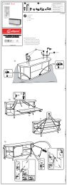
<strong>The</strong> <strong>Air</strong> Shadow <br />
Traditional Ceiling Fan<br />
WARNING: Support Directly<br />
From Building Structure<br />
Net Weight 12.47 kg (27.5 lbs)<br />
Model No. FP825**<br />
OWNER’S MANUAL<br />
READ AND SAVE THESE INSTRUCTIONS<br />
For Canada, this fan must be secured directly to the building structure or ceiling joist.<br />
Don’t secure this fan to an outlet box.
Important Safety Instructions<br />
WARNING: To avoid fire, shock and serious personal injury, follow these instructions.<br />
1. Read your owner’s manual and safety information before installing your new fan. Review the accompanying assembly diagrams.<br />
2. Before servicing or cleaning unit, switch power off at service panel and lock service panel disconnecting means to prevent power<br />
from being switched on accidentally. When the service disconnecting means cannot be locked, securely fasten a warning device, such<br />
as a tag, to the service panel.<br />
3. Be careful of the fan and blades when cleaning, painting, or working near the fan. Always turn off the power to the ceiling fan before<br />
servicing.<br />
4. Do not insert anything into the fan blades while the fan is operating.<br />
5. Do not operate reversing switch until fan blades have come to a complete stop.<br />
Additional Safety Instructions<br />
1. To avoid possible shock, be sure electricity is turned off at the fuse box before wiring, and do not operate fan without blades.<br />
2. All wiring and installation procedures must satisfy National Electrical Codes (ANSI/ NFPA 70-1999) and Local Codes. <strong>The</strong> ceiling fan<br />
must be grounded as a precaution against possible electrical shock. Electrical installation should be made or approved by a licensed<br />
electrician.<br />
3. <strong>The</strong> fan base must be securely mounted and capable of reliably supporting at least 50 lbs. (fan and accessories not to exceed 50 lbs.<br />
or 22.7 kgs.). See page 4 of owner’s manual for support requirements. Consult a qualified electrician if in doubt.<br />
WARNING: Mount only to an outlet box marked acceptable for fan support.<br />
4. <strong>The</strong> fan must be mounted with the fan blades at least 7 feet from the floor to prevent accidental contact with the fan blades.<br />
5. Follow the recommended instructions for the proper method of wiring your ceiling fan. If you do not have adequate electrical<br />
knowledge or experience, have your fan installed by licensed electrician.<br />
6. Suitable for use with solid-state speed controls.<br />
WARNING: To reduce the risk of fire or electric shock, this fan should only be used with Fan Speed Control Part No. UC7067RC,<br />
manufactured by Rhine Electronic Co., Ltd.<br />
WARNING: TO REDUCE THE RISK OF SHOCK, THIS FAN MUST BE INSTALLED WITH AN ISOLATING WALL CONTROL/SWITCH.<br />
WARNING: This product is designed to use only those parts supplied with this product and/or accessories designated specifically for<br />
use with this product. Using parts and/or accessories not designated for use with this product could result in personal injury or property<br />
damage.<br />
WARNING: To reduce the risk of personal injury, do not bend the blade bracket (flange or blade holder) when installing the brackets,<br />
balancing the blades, or cleaning the fan. Do not insert foreign objects in between rotating fan blades.<br />
LIMITED LIFETIME WARRANTY<br />
Extends to the original purchaser of a <strong>Fanimation</strong> Fan<br />
1. LIMITED LIFETIME MOTOR WARRANTY - If any part of your fan motor fails, due to a defect in materials or workmanship during<br />
the lifetime of the original purchaser, <strong>Fanimation</strong> will provide the replacement part free of charge, when the defective fan is returned<br />
to our national service center. Proof of purchase is required. Customer shall be responsible for all costs incurred in the removal or<br />
reinstallation and shipping of the product for repairs or replacement.<br />
2. ONE YEAR MOTOR LABOR WARRANTY - If your fan motor fails at any time within one year from the original purchase, due to<br />
defects in materials or workmanship, labor to repair the motor will be provided free of charge at our national service center. Purchaser<br />
will be responsible for labor charges after this one-year period. Customer shall be responsible for all costs incurred in the removal or<br />
reinstallation and shipping of the product for repairs or replacement.<br />
3. If any other part of your fan fails at any time within one year after original purchase, due to a defect in materials or workmanship, we<br />
will repair, or replace, at our option, the defective part free of charge for parts and labor performed at our national service center.<br />
4. Because of varying climate conditions, this warranty does not cover changes in the finish, including rusting, pitting, corroding,<br />
tarnishing, or peeling.<br />
5. This warranty is void and does not apply to damage from improper installation, neglect, accident, misuse, exposure to extremes of<br />
heat or humidity, or as a result of any modification to the original product.<br />
6. All costs of removal and reinstallation of the fan are the sole responsibility of the owner of the fan and not the store that sold the fan<br />
or <strong>Fanimation</strong>.<br />
7. <strong>Fanimation</strong> reserves the right to modify or discontinue any product at any time and may substitute any part under this warranty.<br />
8. Under no circumstances may a fan be returned without prior authorization from <strong>Fanimation</strong>. <strong>The</strong> receipt of purchase must accompany<br />
authorized returns and must be sent freight prepaid to <strong>Fanimation</strong>. <strong>The</strong> fan to be returned must be properly packed to avoid<br />
damage in transit; <strong>Fanimation</strong> will not be responsible for any damage resulting from improper packaging.<br />
9. It is understood that any repair or replacement is the exclusive remedy available from <strong>Fanimation</strong>. <strong>The</strong>re is no other expressed or<br />
implied warranty. <strong>Fanimation</strong> hereby disclaims any and all implied warranties, including, but not limited to those of merchantability and<br />
fitness for a particular purpose to the extent permitted by law. Some states do not allow limitations on implied warranties. <strong>Fanimation</strong><br />
will not be liable for incidental, consequential, or special damages arising out of or in conjunction with product use or performance,<br />
except as may otherwise be accorded by law. This warranty gives you special legal rights and you may also have other rights that vary<br />
from state to state.<br />
10. A certain amount of wobble is normal and should not be considered a problem or a defect.<br />
Table of Contents<br />
Unpacking Instructions . . . . . . . . . . . . . . . . . . . . . . . . . . . . . . . . . . . . . . . . . . . . . . . . . . . . . . . . . . . . . . . . . . 3<br />
Electrical and Structural Requirements . . . . . . . . . . . . . . . . . . . . . . . . . . . . . . . . . . . . . . . . . . . . . . . . . . . . . 4<br />
How to Assemble Your Ceiling Fan . . . . . . . . . . . . . . . . . . . . . . . . . . . . . . . . . . . . . . . . . . . . . . . . . . . . . . . . . 4<br />
How to Hang Your Ceiling Fan. . . . . . . . . . . . . . . . . . . . . . . . . . . . . . . . . . . . . . . . . . . . . . . . . . . . . . . . . . . . . 6<br />
How to Wire Your Ceiling Fan - C28 Remote Control . . . . . . . . . . . . . . . . . . . . . . . . . . . . . . . . . . . . . . . . . . 7<br />
How to Operate Your C28 Remote Control . . . . . . . . . . . . . . . . . . . . . . . . . . . . . . . . . . . . . . . . . . . . . . . . . . . 8<br />
Installing the Canopy Housing . . . . . . . . . . . . . . . . . . . . . . . . . . . . . . . . . . . . . . . . . . . . . . . . . . . . . . . . . . . . 8<br />
Maintenance . . . . . . . . . . . . . . . . . . . . . . . . . . . . . . . . . . . . . . . . . . . . . . . . . . . . . . . . . . . . . . . . . . . . . . . . . . . 8<br />
Blade Cleaning . . . . . . . . . . . . . . . . . . . . . . . . . . . . . . . . . . . . . . . . . . . . . . . . . . . . . . . . . . . . . . . . . . . . . . . . . 8<br />
Trouble Shooting. . . . . . . . . . . . . . . . . . . . . . . . . . . . . . . . . . . . . . . . . . . . . . . . . . . . . . . . . . . . . . . . . . . . . . . . 9<br />
Installing the LK825 . . . . . . . . . . . . . . . . . . . . . . . . . . . . . . . . . . . . . . . . . . . . . . . . . . . . . . . . . . . . . . . . . . . . 10<br />
Parts List . . . . . . . . . . . . . . . . . . . . . . . . . . . . . . . . . . . . . . . . . . . . . . . . . . . . . . . . . . . . . . . . . . . . . . . . . . . . . 12<br />
Exploded-View Illustration . . . . . . . . . . . . . . . . . . . . . . . . . . . . . . . . . . . . . . . . . . . . . . . . . . . . . . . . . . . . . . . 13
This Manual is Designed to Make it as Easy as Possible for You<br />
to Assemble, Install, Operate, and Maintain Your Ceiling Fan<br />
Tools Needed for Assembly Materials<br />
• One Phillips head screwdriver<br />
• One stepladder<br />
• One ¼˝ blade screwdriver<br />
Wiring outlet box and box connectors must be of type<br />
required by local code. <strong>The</strong> minimum wire would be a 3conductor<br />
(2-wire with ground) of the following size:<br />
Installed Wire Length<br />
Up to 50 ft.<br />
50 - 100 ft.<br />
Wire Size A.W.G.<br />
14<br />
12<br />
NOTE: Place the parts from the loose parts bags in a small<br />
container to keep them from being lost. If any parts are missing,<br />
contact your local retailer.<br />
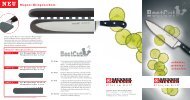
Unpacking Instructions<br />
For your convenience, check-off each step. As each step is completed, place a check mark. This will ensure that all<br />
steps have been completed and will be helpful in fi nding your place should you be interrupted.<br />
1. Check to see that you have received the following<br />
parts:<br />
NOTE: If you are uncertain of part description, refer to<br />
exploded view illustration. (Figure 1, page 13)<br />
Hanger Bracket<br />
▲WARNING<br />
Fan Motor Assembly<br />
• One wire stripper<br />
• Three wire connectors<br />
(supplied)<br />
Before assembling your ceiling fan, refer to section on<br />
proper method of wiring your fan (page 4). If you feel you<br />
do not have enough wiring knowledge or experience,<br />
have your fan installed by a licensed electrician.<br />
▲WARNING<br />
Do not install or use fan if any part is damaged or<br />
missing. This product is designed to use only those<br />
parts supplied with this product and/or any accessories<br />
designated specifically for use with this product by<br />
<strong>Fanimation</strong>. Substitution of parts or accessories not<br />
designated for use with this product by <strong>Fanimation</strong> could<br />
result in personal injury or property damage. Contact<br />
your retail store for missing or damaged parts.<br />
Ceiling Canopy<br />
Light Kit Upper Assembly<br />
Hardware Bag<br />
3<br />
• Fan Motor assembly<br />
– Support Safety Cable bag<br />
• Light Kit / Parts assembly<br />
• Lower Housing, Light Kit<br />
• Hanger Bracket<br />
• Downrod/Hanger Ball<br />
assembly<br />
• Ceiling Canopy<br />
• Motor Coupling Cover<br />
• C28 Remote Control<br />
• Receiver Unit<br />
Downrod/<br />
Hanger Ball<br />
Assembly<br />
• Hardware bags:<br />
– Two 5/32˝ threaded rods<br />
– Two 5/32˝ lockwashers<br />
– Two knurled knobs<br />
– Three 3/16˝ screws<br />
– Three 3/16˝ lockwashers<br />
– Seven wire nuts<br />
– Phillips screwdriver, 4˝<br />
– Finial nut<br />
• Lower Housing Mount<br />
Hardware bag:<br />
– Hex nut<br />
– Two wire nuts<br />
Light Kit<br />
Lower Housing<br />
Receiver Unit<br />
Motor<br />
Coupling<br />
Cover<br />
Finial Nut<br />
C28 Remote<br />
Control
Electrical and Structural Requirements<br />
Your new ceiling fan will require a grounded electrical<br />
supply line of 120 volts AC, 60 Hz, 15 amp circuit. <strong>The</strong><br />
outlet box must be securely anchored and capable of<br />
withstanding a load of at least 22.7 kgs (50 lbs). Figure 1<br />
depicts different structural configurations that may be used<br />
for mounting the outlet box.<br />
▲WARNING<br />
To reduce the risk of fire, electrical shock, or personal<br />
injury, mount fan to outlet box marked acceptable<br />
for fan support of 22.7 kg (50 lbs) or less. Use screws<br />
supplied with outlet box. Most outlet boxes commonly<br />
used for support of light fixtures are not acceptable for<br />
fan support and may need to be replaced. Consult a<br />
qualified electrician if in doubt.<br />
If your fan is to replace an existing light fixture, turn<br />
electricity off at the main fuse box at this time and remove<br />
the existing light fixture.<br />
▲WARNING<br />
Turning off wall switch is not sufficent. To avoid<br />
possible electrical shock, be sure electricity is turned<br />
off at the main fuse box before wiring. All wiring must<br />
be in accordance with National and Local codes and the<br />
ceiling fan must be properly grounded as a precaution<br />
against possible electrical shock.<br />
1. Prior to assembly, set aside and save the hardware<br />
bag(s) packed in the packing.<br />
2. Remove the Hanger Ball by loosening the setscrew<br />
in the Hanger Ball until the ball falls freely down the<br />
Downrod. (Figure 1) Remove the Pin from the Downrod,<br />
then remove the Hanger Ball. Retain the Pin and Hanger<br />
Ball for reinstallation in Step 8.<br />
3. <strong>The</strong> fan comes with blue, black, gray and white 80˝<br />
wires. Separate and untwist the wires. Route the wires<br />
through the Downrod.<br />
NOTE: You will be using either the 6˝ downrod supplied with<br />
your fan or an optional downrod purchased seperately.<br />
4. Position Fan/Motor Assembly on styrofoam pedestal, for<br />
ease of assembly.<br />
5. Loosen the two setscrews in the Downrod Support. Align<br />
the Clevis Pin holes in the Downrod with the holes in the<br />
Downrod Support. Install the Clevis Pin and secure with<br />
the Hairpin Clip. (Figure 2) Be sure to push the straight<br />
leg of the hairpin clip through the hole near the end of the<br />
clevis pin until the curved portion of the hairpin clip snaps<br />
around the clevis pin. <strong>The</strong> hairpin clip must be properly<br />
installed to prevent the clevis pin from working loose. Pull<br />
on the Downrod to make sure the clevis pin is properly<br />
installed. (Figure 2)<br />
4<br />
Ceiling<br />
Joists<br />
Ceiling<br />
How to Assemble Your Ceiling Fan<br />
Setscrew<br />
Downrod<br />
Support<br />
Figure 1<br />
▲WARNING<br />
Figure 1<br />
Figure 2<br />
Pin<br />
2˝ x 4˝<br />
Outlet<br />
Box<br />
To avoid fire or shock, follow all wiring instructions<br />
carefully. Any electrical work not described in these<br />
instructions should be done or approved by a licensed<br />
electrician.<br />
Hanger<br />
Ball<br />
Motor<br />
Coupling<br />
Cover<br />
Hairpin Clip<br />
Clevis Pin<br />
Setscrew (2)
How to Assemble Your Ceiling Fan (cont’d)<br />
6. Route wires through opening in Motor Coupling Cover.<br />
Position Motor Coupling Cover on fan shown with open<br />
side facing down. (Figure 2)<br />
7. Route wires through opening in Canopy. Position<br />
Canopy on fan shown with open side facing up. (Figure 3)<br />
8. Reinstall the Hanger Ball (Figure 3) on the Downrod<br />
as follows. Route the three 80˝ wires through the Hanger<br />
Ball. Position the Pin through the two holes in the Downrod<br />
and align the Hanger Ball so the Pin is captured in the<br />
groove in the top of the Hanger Ball. Pull the Hanger Ball<br />
up tight against the pin. Securely tighten the setscrew<br />
in the Hanger Ball. A loose setscrew could create fan<br />
wobble.<br />
▲WARNING<br />
It is critical that the clevis pin in the downrod support<br />
is properly installed and the setscrews are securely<br />
tightened. Failure to verify that the pin and setscrews<br />
are properly installed could result in the fan falling.<br />
9. While pulling up on the hanger ball, securely tighten<br />
the two 3/16-24 x 3/8˝ setscrews in the downrod support.<br />
(Figure 2)<br />
NOTE: <strong>The</strong> setscrews must be properly installed as<br />
described above, or fan-wobble could result.<br />
10. Slide the Motor Coupling Cover down until it touches<br />
the top of the Housing. (Figure 3)<br />
11. <strong>The</strong> fan comes with blue, black, gray and white leads.<br />
Before installing fan, measure up approximately 6-9 inches<br />
above top of Downrod/Hanger Ball Assembly. Cut off<br />
excess wire and strip back insulation ½˝ from end of wire.<br />
12. You have now completed the assembly of your new<br />
ceiling fan. You can now proceed with the hanging and the<br />
electrical wiring of your fan.<br />
5<br />
Downrod/Hanger<br />
Ball Assembly<br />
Ceiling<br />
Canopy<br />
Motor<br />
Coupling<br />
Cover<br />
Figure 3
▲WARNING<br />
To avoid possible electrical shock, be sure electricity is<br />
turned off at the main fuse box before hanging.<br />
NOTE: If you are not sure if the outlet box is grounded,<br />
contact a licensed electrician for advice, as it must be<br />
grounded for safe operation.<br />
▲WARNING<br />
<strong>The</strong> fan must be hung with at least 7´ of clearance from<br />
floor to blades (Figure 1)<br />
▲WARNING<br />
<strong>The</strong> outlet box must be securely anchored and capable<br />
of withstanding a load of at least 50 lbs. Hanger bracket<br />
must seat firmly against outlet box. If the outlet box is<br />
recessed, remove wallboard until bracket contacts box.<br />
If bracket and/or outlet box are not securely attached,<br />
the fan could wobble or fall.<br />
1. Using the 3 ⁄8˝ x 2˝ lag bolt and flat washer, attach<br />
safety cable to ceiling joist or wood structural member.<br />
<strong>The</strong> lag bolt will pass through the flat washer, safety<br />
cable loop, the junction box and into the building structure<br />
(Figure 2). You will first drill a ¼˝ pilot hole into the<br />
building structure to prevent splitting or cracking.<br />
2. Securely attach the hanger bracket to ceiling junction<br />
box acceptable for ceiling support.<br />
NOTE: Ceiling support cable cannot be secured to<br />
junction box only, it must be directly secured to ceiling<br />
joist or structural member using the ⅜˝ x 2˝ lag bolt and<br />
fl at washer. (Figure 2).<br />
3. Make sure the electrical supply wires, including the<br />
hanger bracket grounding wire and safety cable are<br />
pulled through the downrod, between the hanger bracket<br />
and the junction box so that electrical connections can be<br />
made later.<br />
4. Carefully lift the fan and seat the downrod/hanger ball<br />
assembly on the hanger bracket that was just attached to<br />
the ceiling joist. Be sure the groove in the ball is lined up<br />
with tab on the hanger bracket. (Figure 3)<br />
5. Attach the safety cable to ceiling support cable. Slide<br />
cable clamp onto safety cable (from fan). Place the end<br />
of cable through the loop of ceiling support cable. Pull as<br />
much cable through loop as possible. Feed end of cable<br />
into clamp hole and firmly tighten screw (Figure 3). Cut<br />
off excess safety cable.<br />
▲WARNING<br />
Failure to seat tab in groove could cause damage to<br />
electrical wires and possible shock or fire hazard.<br />
▲WARNING<br />
To avoid possible shock, do not pinch wires between the<br />
downrod/hanger ball assembly and the hanger bracket.<br />
How to Hang Your Ceiling Fan<br />
6<br />
Ceiling<br />
Wood Member<br />
(2˝ x 4˝ Approx.)<br />
Ceiling<br />
Support<br />
Cable<br />
Attach<br />
Safety Cable to<br />
Ceiling Support<br />
Cable<br />
Tab<br />
NOTE: Supply wires and<br />
fan wires omitted for clarity<br />
Figure 1<br />
Figure 2<br />
Figure 3<br />
Floor<br />
Ceiling Joist<br />
No<br />
less than<br />
7 ft<br />
Junction<br />
Box<br />
Hanger Bracket<br />
Downrod/Hanger<br />
Ball Assembly
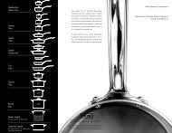
How to Wire Your Ceiling Fan - C28 Remote Control<br />
If you feel that you do not have enough electrical wiring knowledge or experience, have your fan installed by a<br />
licensed electrician.<br />
▲WARNING<br />
To avoid possible electrical shock, be sure electricity is<br />
turned off at the main fuse box before wiring.<br />
NOTE: If you are not sure if the outlet box is grounded,<br />
contact a licensed electrician for advice, as it must be<br />
grounded for safe operation.<br />
1. Setting the Code: <strong>The</strong> remote unit has 16 different<br />
code combinations. It may be necessary to test a couple<br />
frequency code settings to improve signal reception<br />
and/or eliminate interference from other remote control<br />
household items. Multiple fans should have different code<br />
settings to allow independent fan control. To set the code,<br />
perform these steps.<br />
• Transmitter: remove battery cover. Press fi rmly below<br />
arrow and slide battery cover off. Slide code switches to<br />
your choice of up or down position. Factory setting is all<br />
up. Do not use this position. With a small screwdriver or<br />
ball point pen slide fi rmly up or down (Figure 1a). Replace<br />
battery cover on the transmitter.<br />
• Receiver: Slide code switches to the same positions<br />
as set on your transmitter (Figure 1b).<br />
2. Installing Receiver in Hanger Bracket:<br />
• Slide remote Receiver into the Hanger Bracket<br />
(Figure 2).<br />
• Connect wires as indicated: (Figure 3)<br />
• Green Hanger Bracket & Hanger Ball wires to BARE<br />
(ground) wire.<br />
• BLACK Receiver Unit wire (AC IN L) to BLACK supply<br />
wire.<br />
• WHITE Receiver Unit wire (AC IN N). to WHITE supply<br />
wire.<br />
• WHITE Receiver Unit wire (TO MOTOR N) to WHITE<br />
fan wire.<br />
• BLACK Receiver Unit wire (TO MOTOR L) to BLACK<br />
fan wire.<br />
• BLUE Receiver Unit wire (FOR LIGHT DOWN) to BLUE<br />
light wire.<br />
• GRAY Receiver Unit wire (REVERSE MODULE) to<br />
GRAY wire.<br />
• Position all connected wires and receiver antenna to<br />
allow installation of ceiling canopy.<br />
• Using canopy screws threaded into the hanger bracket<br />
install ceiling canopy. (see page 8)<br />
3. After making the wire connections, the wires should<br />
be spread apart, turned upward and pushed carefully up<br />
into the outlet box, with the grounded conductor and the<br />
equipment-grounding conductor on one side of the outlet<br />
box and the ungrounded conductor on the other side of the<br />
outlet box.<br />
7<br />
Remote Transmitter<br />
Unit Detail<br />
9V<br />
Battery<br />
GRN from hanger ball<br />
GRN from bracket<br />
Figure 1a<br />
GRN or BARE GROUND<br />
WH-TO MOTOR N<br />
BLK-TO MOTOR L<br />
GRAY-REVERSE MODULE<br />
BLUE-FOR LIGHT DOWN<br />
Reciever Unit Detail<br />
Figure 1b<br />
NOTE: If fan or supply wires are different colors<br />
than indicated, have this unit installed by a qualifi ed<br />
electrician.<br />
Ceiling<br />
Bracket<br />
(Open End) Receiver Unit<br />
NOTE: Receiver wires omitted for clarity.<br />
Figure 2<br />
Figure 3<br />
BLK-ANT<br />
▲WARNING<br />
WH-AC IN N<br />
BL-AC IN L<br />
120 VAC SUPPLY<br />
(User Supplied)<br />
Check to see that all connections are tight, including<br />
ground, and that no bare wire is visible at the wire<br />
connectors, except for the ground wire. Do not operate<br />
fan until the blades is in place. Noise and fan damage<br />
could result.
How to Operate Your C28 Remote Control<br />
1. Operating & Using Remote Transmitter (Figure 1):<br />
Install 9 volt battery (If not using for long periods of time,<br />
remove battery to prevent damage to transmitter). Store<br />
the transmitter away from excess heat or humidity.<br />
• HI Push Button – high fan speed<br />
• MED Push Button – medium fan speed<br />
• LOW Push Button – low fan speed<br />
• OFF Push Button – fan off<br />
• REV Push Button – toggles between air upflow and<br />
air downflow<br />
• *Demo Push Button – on/off auto demo mode<br />
• Light Push Button – on/off and brightness control for<br />
optional down light.<br />
To control either light hold down key to increase or<br />
decrease brightness. Tap key quickly to turn light on or<br />
off. <strong>The</strong> light keys have auto resume and will stay at the<br />
same brightness as the last time it was turned off.<br />
NOTE: This step is applicable after the neccessary wiring<br />
is completed. (see page 7)<br />
▲WARNING<br />
To avoid possible fire or shock, make sure that the<br />
electrical wires are completely inside the canopy housing<br />
and not pinched between the housing and the ceiling.<br />
1. Screw in two threaded rods into the Hanger Bracket<br />
(Figure 1a).<br />
NOTE: <strong>The</strong> threaded rods in the hanger bracket serve as<br />
guides for easier installation.<br />
2. Securely attach the Canopy Housing to the Hanger<br />
Bracket using the external lockwashers and knurled knobs<br />
supplied with your fan (Figure 1b).<br />
Periodic cleaning of your new ceiling fan is the only<br />
maintenance that is needed.<br />
When cleaning, use only a soft brush or lint free cloth to<br />
avoid scratching the fi nish.<br />
Abrasive cleaning agents are not required and should be<br />
avoided to prevent damage to fi nish.<br />
Periodic light dusting of the blades is recommended.<br />
A feather duster will work best.<br />
Installing the Canopy Housing<br />
Maintenance<br />
Blade Cleaning<br />
8<br />
Figure 1<br />
*Demo mode is initiated by pressing the Demo button<br />
on the remote, lights will fl ash 3 times. Fan runs for 2½<br />
minutes then shuts off for ½ minute. <strong>The</strong> 2 ½ / ½ minute<br />
run cycles continue until any other button is pressed on<br />
the remote control.<br />
NOTE: Supply wires and fan wires omitted for clarity.<br />
Figure 1a Figure 1b<br />
CAUTION<br />
Do not use water when cleaning your ceiling fan. It could<br />
damage the motor or the finish and create the possibility<br />
of electrical shock.<br />
Avoid using water, cleansers, or harsh rags, which can<br />
warp and ruin the blade and the fi nish.
Trouble Shooting<br />
▲WARNING<br />
For your own safety turn off power at fuse box or circuit breaker before trouble shooting your fan.<br />
Trouble Probable Cause Suggested Remedy<br />
1. FAN WILL NOT START<br />
2. FAN SOUNDS NOISY<br />
3. FAN WOBBLES<br />
EXCESSIVELY<br />
4. NOT ENOUGH AIR<br />
MOVEMENT<br />
1. Fuse or circuit breaker blown.<br />
2. Loose power line connections to the fan, or loose<br />
switch wire connections in the switch housing.<br />
3. Dead battery in remote control.<br />
1. Loose screws in motor housing.<br />
2. Wire connectors inside housing rattling.<br />
3. Motor noise caused by solid state variable speed<br />
control.<br />
4. Screws holding blades to blade holders are loose.<br />
5. Lower housing support set screw loose.<br />
1. Setscrew in downrod support is loose.<br />
2. Setscrew in downrod/hanger ball assembly is loose.<br />
3. Screws securing fan blade holders to motor hub are<br />
loose.<br />
4. Hanger bracket and/or ceiling outlet box is not<br />
securely fastened.<br />
9<br />
1. Check main and branch circuit fuses or circuit<br />
breakers.<br />
2. Check line wire connections to fan and switch wire<br />
connections in the switch housings.<br />
CAUTION: Make sure main power is turned off !<br />
3. Replace with fresh battery.<br />
1. Check to make sure all screws in motor housing are<br />
snug (not over-tight).<br />
2. Check to make sure wire connectors in switch<br />
housing are not rattling against each other or against<br />
the interior wall of the switch housing.<br />
CAUTION: Make sure main power is turned off !<br />
3. Some fan motors are sensitive to signals from<br />
solid-state variable speed controls. Solid-state controls<br />
are not recommended, choose an alternative control<br />
method.<br />
4. Tighten screws securely.<br />
5. Tighten set screw securely.<br />
1. Tighten both setscrews securely in downrod support.<br />
2. Tighten the setscrew in the downrod/hanger ball<br />
assembly.<br />
3. Check to be sure screws which attach the fan blade<br />
holders to the flywheel are tight.<br />
4. Tighten the hanger bracket screws to the outlet box,<br />
and secure outlet box.<br />
1. If possible, consider using a longer downrod. For<br />
example, use a 12” downrod instead of the 6” downrod<br />
that comes with your fan.
CAUTION<br />
Turning off wall switch is not sufficient. To avoid<br />
possible electrical shock, be sure electricity is turned<br />
off at the main fuse box before wiring. All wiring must<br />
be in accordance with National and Local codes and the<br />
ceiling fan must be properly grounded as a precaution<br />
against possible electrical shock.<br />
1. Locate accessory mounting plate on bottom of fan.<br />
Installing the LK825**<br />
10<br />
▲WARNING<br />
To avoid fire or shock, follow all wiring instructions<br />
carefully. Any electrical work not described in these<br />
instructions should be done or approved by a licensed<br />
electrician.<br />
Figure 1 Figure 2<br />
2. Install nut and nipple bracket assembly on the fan motor<br />
nipple end before mounting the 5-light bowl.<br />
Figure 3 Figure 4<br />
3. Mount 5-light bowl unit on accessory mounting plate<br />
with 3 screws and 3 lockwashers provided.<br />
4. Locate white and blue wires labeled “FOR LIGHT”.<br />
Connect white-to-white and blue-to-black wires with wire<br />
nuts supplied.
Installing the LK825** (cont’d)<br />
Figure 5 Figure 6<br />
5. Install lower housing. 6. Install finial nut on end of nipple, do not over tighten.<br />
Figure 7 Figure 8<br />
7. Install glass shades (not included). 8. Install 60 watt med-base bulbs (not included).<br />
11
Parts List<br />
Model #FP825**<br />
Ref. # Description Part #<br />
Retractable Fan Assembly – Traditional FP825 <br />
5<br />
FAN MOTOR ASSEMBLY — MAR20CY<br />
Retractable Fan Motor Assembly —<br />
9 Control Receiver RECCAN57DEMO<br />
10 Remote Control<br />
Support Cable Bag Containing:<br />
Ceiling Support Cable<br />
Cable Clamp<br />
Flat Washer<br />
Lag Bolt,<br />
C28<br />
3 /8˝ x 2˝<br />
TRADITIONAL LIGHT KIT ASSEMBLY — LK825**<br />
6 5-Socket Light Kit Assembly AP82530 7 Lower Housing, Light Kit P82515 <br />
1 Hanger Bracket Assembly APG610BL<br />
2 Ball/Downrod Assembly ADR1x6 3 Ceiling Canopy PG165 <br />
4 Motor Coupling Cover P81090<br />
8<br />
Hardware Bag(s) Containing:<br />
Wire Nut (7)<br />
Finial Nut<br />
Canopy Hardware Bag Containing:<br />
5 /32˝ Threaded Rods (2)<br />
5 /32˝ External Lockwasher (2)<br />
Knurled Knobs (2)<br />
Housing Mount Hardware Bag Containing:<br />
3 /16˝ Pan Head Screw (3)<br />
3 /16˝ External Lockwasher (3)<br />
Phillips Screwdriver, 4˝<br />
Lower Housing Mounting Hardware Bag Containing:<br />
C-Bracket / Threaded Rod Assembly<br />
Hex Nut<br />
Wire Nut (2)<br />
Insert FINISH CODES (Refer to fan model number located on downrod support)<br />
Before discarding packaging materials, be certain all parts have been removed<br />
How To Order Parts<br />
Contact your retail store for repair parts.<br />
When ordering repair parts, always<br />
give the following information.<br />
12<br />
HDWLK825 <br />
• Part Number<br />
• Part Description<br />
• Fan Model Number
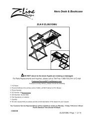
5<br />
3<br />
1<br />
4<br />
2<br />
<strong>The</strong> <strong>Air</strong> Shadow Fan FP825**<br />
Exploded-View<br />
Figure 1<br />
NOTE: <strong>The</strong> illustration shown is not to scale or its actual confi guration may vary<br />
13<br />
6<br />
7<br />
8 ref<br />
9<br />
8 ref<br />
8<br />
10
Copyright 2007 <strong>Fanimation</strong><br />
10983 Bennett Parkway<br />
Zionsville, IN 46077<br />
(888) 567-2055<br />
FAX (866) 482-5215<br />
Outside U.S. call (317) 733-4113<br />
Visit Our Website www.fanimation.com<br />
2007/01