multigap pseudospark switch for fair - GSI Helmholtzzentrum für ...
multigap pseudospark switch for fair - GSI Helmholtzzentrum für ...
multigap pseudospark switch for fair - GSI Helmholtzzentrum für ...

You also want an ePaper? Increase the reach of your titles
YUMPU automatically turns print PDFs into web optimized ePapers that Google loves.
Abstract<br />
MULTIGAP PSEUDOSPARK SWITCH FOR FAIR<br />
K. Frank, I. Petzenhauser*, U. Blell*, B.J. Lee + , and J. Jacoby +<br />
Texas Tech University<br />
Center <strong>for</strong> Pulsed Power and Power Electronics<br />
Box 43102, Lubbock, Tx, 79409-3102, United States<br />
E-mail: klaus.frank@ttu.edu<br />
At the <strong>GSI</strong> <strong>Helmholtzzentrum</strong> fuer Schwerionen<strong>for</strong>schung<br />
GmbH a new accelerator complex, called Facility <strong>for</strong><br />
Antiproton and Ion Research (FAIR), is under construction.<br />
Its main components are the SIS100 and SIS300 heavy ion<br />
synchrotrons. To operate their injection/extraction kicker<br />
magnet systems, modulators with pulse-<strong>for</strong>ming networks<br />
(PFNs) are necessary. The PFNs will be charged to a high<br />
voltage up to 70 kV and discharged via a high-voltage<br />
<strong>switch</strong>. The <strong>switch</strong> has to handle currents up to 6 kA, pulse<br />
durations up to 7 microseconds with an overall lifetime<br />
exceeding 10 8 shots. The repetition rate is about 4 Hz and a<br />
current rise rate of at least 4 . 10 10 A/s is required. The only<br />
commercially available <strong>switch</strong> in this parameter range is<br />
actually a multi-gap thyratron. As an alternative, a three-gap<br />
<strong>pseudospark</strong> <strong>switch</strong> is under development at <strong>GSI</strong>. It<br />
combines the major advantages of the thyratron with its low<br />
stand-by power as a cold-cathode device, as well as its<br />
insensitivity to large current reversal.<br />
Like <strong>for</strong> the thyratron, the maximum hold-off voltage of a<br />
single gap <strong>pseudospark</strong> <strong>switch</strong> is limited to about 35 kV.<br />
For a reliable hold-off voltage of 70 kV, a three-gap system<br />
was designed. Test results with a first sealed-off prototype<br />
<strong>switch</strong> of this design are reported. The prototype has<br />
demonstrated a voltage hold-off capability of more than 80<br />
kV. The circuit of capacitive and resistive voltage dividers<br />
was optimized to improve the <strong>switch</strong> control, the delay and<br />
the jitter values.<br />
As trigger unit, a conventional high-dielectric trigger is<br />
used. With such a trigger unit a crucial issue <strong>for</strong> minimum<br />
delay breakdown still remains the plasma coupling between<br />
the different gaps by drift-spaces. Those drift spaces have to<br />
be designed carefully in order to minimize the internal<br />
delay of breakdown. An additional major issue is that the<br />
<strong>switch</strong> suffers from losses, which principally limit the<br />
lifetime of low-pressure gas discharge <strong>switch</strong>es. At high<br />
repetition rates a common way to minimize losses by anode<br />
dissipation is to integrate a so-called anode inductor.<br />
Whether this will be true, too, with a cold-cathode <strong>switch</strong> at<br />
low repetition rates, and much larger pulse lengths,<br />
preliminary tests with an anode inductor were per<strong>for</strong>med.<br />
I. INTRODUCTION<br />
The "Facility <strong>for</strong> Antiproton and Ion Research" (FAIR) is a<br />
new, international accelerator complex that will be built in<br />
Darmstadt, Germany [1]. The project started officially in<br />
November 2007. One of the main components of this<br />
complex will be the SIS100/300 double ring facility with a<br />
circumference of 1100 m. SIS indicates the type of the<br />
machine "Schwer-Ionen-Synchrotron" which is the German<br />
word <strong>for</strong> heavy ion synchrotron and the numbers<br />
correspond to the maximum beam rigidity of 100 Tm and<br />
300 Tm, respectively.<br />
Kicker magnets are fast pulsed devices used <strong>for</strong> the<br />
injection and ejection of particle beams of such circular<br />
accelerators. Frequently the space available in the<br />
accelerator lattice <strong>for</strong> these magnets is strictly limited,<br />
resulting in difficulties in simultaneously satisfying the kick<br />
strength and fast rise time requirements. The obvious<br />
solution of further raising the voltage runs into technical<br />
difficulties above 80-100 kV. Fortunately, operating kicker<br />
magnets in the short-circuited rather than the terminated<br />
mode generates double the kick strength from a given space<br />
<strong>for</strong> given operating voltage, characteristic impedance and<br />
rise time.<br />
II. THE NEW THREE-GAP PSS<br />
PROTOTYPE<br />
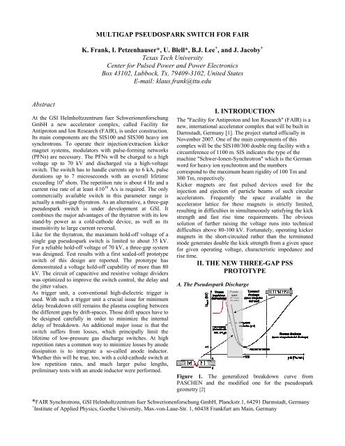
A. The Pseudospark Discharge<br />
Figure 1. The generalized breakdown curve from<br />
PASCHEN and the modified one <strong>for</strong> the <strong>pseudospark</strong><br />
geometry [2]<br />
*FAIR Synchrotrons, <strong>GSI</strong> <strong>Helmholtzzentrum</strong> fuer Schwerionen<strong>for</strong>schung GmbH, Planckstr.1, 64291 Darmstadt, Germany<br />
+ Institute of Applied Physics, Goethe University, Max-von-Laue-Str. 1, 60438 Frankfurt am Main, Germany
Due to the non-planar geometry (see Figure 1.) of the<br />
<strong>pseudospark</strong>, PASCHEN’s law is difficult to apply. This is<br />
a result of both the non-equilibrium nature of the electron<br />
transport and of the difficulty in defining an effective path<br />
length. Since <strong>pseudospark</strong>s operate on the “near side” of<br />
PASCHEN’s curve (i.e increasing hold-off voltage Ubreak,<br />
with a decreasing product of pressure and distance, p*d),<br />
electrons having longer paths will decrease U, due to their<br />
having more opportunity to avalanche be<strong>for</strong>e reaching the<br />
anode. Since the spatial distribution of the electric field,<br />
both in the gap and in the hollow electrode structures,<br />
depends on parameters such as the electrode separation,<br />
electrode thickness, and electrode hole radii, the breakdown<br />
voltage Ubreak, will also depend on these quantities.<br />
Deviations from PASCHEN’s law resulting in lower holdoff<br />
voltages are caused by penetration of the anode potential<br />
into the hollow cathode making a larger effective value of<br />
p * d. Penetration increases with increasing cathode hole<br />
radius and decreasing cathode thickness, and so the hold-off<br />
voltage decreases. Ionizing collisions occur predominantly<br />
near the central hole by electrons initially emitted from the<br />
inside of the cathode. This behavior is a consequence of the<br />
electrons in the hollow cathode spending a longer time in<br />
the moderate electric fields resulting from potential<br />
penetration into the cathode. They also have a longer<br />
effective path length to the anode resulting in a large p*d. In<br />
the hollow anode case, the majority of electron impact<br />
ionization occurs in the cathode hole and near gap. Once the<br />
electrons get into the high-field region in the gap and<br />
accelerate to energies greater than the peak in the ionization<br />
cross section, the rate of ionization decreases dramatically.<br />
Those electrons become so-called “run-away” electrons,<br />
which start to <strong>for</strong>m an energetic e-beam. This is an<br />
undesired process within low-pressure plasma <strong>switch</strong>es like<br />
thyratrons and <strong>pseudospark</strong>s. The overwhelming part of the<br />
commutation loss is related to this process, as well as major<br />
electrode erosion. That is why the limit in hold-off voltage<br />
is at about 30 kV <strong>for</strong> a two-electrode, low-pressure gap; <strong>for</strong><br />
higher hold-of voltages a stacking of two or more gaps is<br />
mandatory. For a reliable hold-off voltage of 70 kV during<br />
an extended lifetime, a number of at least three gaps are<br />
necessary.<br />
B. Comparison Of Switch Types Considered For<br />
Application With FAIR<br />
The following table summarizes the different types of high<br />
voltage <strong>switch</strong>es that have been discussed. When the project<br />
started 5 years ago, solid-state <strong>switch</strong>es were far from being<br />
an useful alternative. Meanwhile the technology of solidstate<br />
<strong>switch</strong>es is so mature that even <strong>for</strong> high voltages<br />
beyond 50 kV those are serious alternatives to gas-filled<br />
devices. But these <strong>switch</strong>es still suffer from an insufficient<br />
current rise rate.<br />
On the other hand high-voltage, <strong>multigap</strong> thyratrons are still<br />
in wide-spread use in high energy particle accelerators and<br />
are still considered <strong>for</strong> future applications.<br />
Table 1: Comparison of different <strong>switch</strong> types related to the<br />
requirements<br />
Parameter Quantity Thyratron Pseudo- Solid- Spark<br />
spark State Gap<br />
Voltage ≤ 70 kV yes yes yes yes<br />
Current ≤ 6 kA yes yes yes yes<br />
Repetition<br />
rate<br />
≤ 4 Hz yes yes yes yes<br />
Pulse<br />
duration<br />
≤ 7 µs yes yes yes yes<br />
Current rise<br />
time<br />
< 150 ns yes yes yes yes<br />
Current rise >4*10<br />
rate<br />
10 A/s yes yes no yes<br />
Energy /<br />
pulse<br />
~ 1,5 kJ yes yes yes yes<br />
Peak power ~ 210 MW yes yes yes yes<br />
Lifetime >10 8 shots yes yes? yes no<br />
The PSS is comparable in many aspects to the thyratron and<br />
it possesses additional advantages, but it is not yet<br />
commercially available. Spark gaps can not fulfill the<br />
lifetime requirements.<br />
C. Pseudospark Development For FAIR<br />
Figure 2 reflects the progress in brazing technology by the<br />
comparison of the <strong>for</strong>mer two-gap prototype (left) [3,4,5]<br />
with the actual three-gap <strong>pseudospark</strong> <strong>switch</strong> (PSS). A<br />
sketch of the drift space lay-out is shown in the middle.<br />
Figure 2. Former two-gap prototype (left), drift space<br />
geometry (middle), actual three-gap prototype (right)<br />
The external circuitry, that divides the voltage between the<br />
three gaps is of big importance <strong>for</strong> delay and jitter values of<br />
the triggered PSS breakdown. Principally it is important to<br />
provide by an auxiliary glow discharge a fast pre-ionization<br />
of the drift space in order to initiate the next gap’s<br />
breakdown. As important as efficient drift-space preionization<br />
is the primary trigger plasma, which initiates the<br />
breakdown process of the <strong>switch</strong>. It is planned to replace<br />
the actual trigger device, the dielectric surface flashover<br />
trigger, by new unit, which has an additional extraction grid<br />
(see Figure 3). This extraction grid, one hand, protects the<br />
device from the impact of the main discharge, on the other<br />
hand, it allows to apply a pre-trigger pulse to improve the
timing, and the extraction of a higher amount of plasma<br />
electrons.<br />
(a)<br />
(b)<br />
Figure 3. Improved trigger unit with parts (a) and crosssection<br />
(b)<br />
The three-gap PSS was tested up to a hold-off voltage of<br />
80 kV. A further increase was prevented by external<br />
flashover at the auxiliary circuit. The <strong>switch</strong>ed current itself<br />
was below 1 kA with the risk of quenching, which was<br />
observed at low gas pressure (as a function of the reservoir<br />
heater current (see Figure 4)).<br />
Figure 4. Quench phenomenon with the three-gap PSS at<br />
different reservoir heater currents, and the influence of<br />
adding a heavy noble gas (argon).<br />
It is well-known from <strong>for</strong>mer experiments with one-gap<br />
<strong>pseudospark</strong> <strong>switch</strong>es that at discharge currents below 1 kA<br />
the quenching [ ] occurs, and, that quenching can be<br />
suppressed by adding a small amount of a heavy noble gas<br />
to the working gas (usually deuterium). This could be<br />
confirmed by experiments with the three-gap PSS (see<br />
Figure 7).<br />
A. Basics<br />
II. SATURABLE INDUCTORS<br />
One of the challenges in all low pressure gas discharge<br />
<strong>switch</strong>es is the reduction of the lifetime due to commutation<br />
losses resulting in anode heating, especially with high<br />
repetition rates. The commutation loss is mainly a result of<br />
the finite <strong>switch</strong>ing time of every <strong>switch</strong>. After the trigger<br />
pulse arrives at the <strong>pseudospark</strong> <strong>switch</strong> (or thyratron), the<br />
gas discharge needs a certain time to fully develop and to<br />
reach a low ohmic resistance. During that commutation<br />
phase, a significant current is already flowing in the <strong>switch</strong>.<br />
The still high voltage and the current multiply to a huge<br />
power loss (Multiflying the still high voltage by the current<br />
results in a huge power loss). This problem can be solved<br />
by using saturable inductors. Basically these inductors,<br />
connected in series to a <strong>switch</strong>, reduce the current flow to a<br />
negligible value. When the inductors are saturated, the<br />
current can flow freely. There<strong>for</strong>e the current is delayed and<br />
the gas discharge inside the <strong>switch</strong> can fully develop be<strong>for</strong>e<br />
the current arrives. When the current flows, the voltage<br />
across the <strong>switch</strong> is already low, there<strong>for</strong>e the losses can be<br />
significantly reduced.<br />
For many decades [13, 14, 15, 16, 17, 18], this method has<br />
been successfully used <strong>for</strong> thyratrons. In contrast to<br />
thyratrons a PSS is based on a cold cathode electrode. To<br />
reach the low-resistive phase in a PSS, a significant current<br />
flow is necessary to allow self-heating of the cathode. A<br />
useful compromise has to be found to fulfill these opposing<br />
needs.<br />
The voltseconds were judged adequate <strong>for</strong> the reactors to<br />
hold off the voltage during the whole of the PSS<br />
commutation period. They are available without the need<br />
<strong>for</strong> pulsed or d.c. bias of the cores. Commutation losses of a<br />
PSS can be determined principally from accurate<br />
measurement of the current and voltage drop during the<br />
<strong>switch</strong>ing period. A loss coefficient can be obtained <strong>for</strong> any<br />
given tube which allows prediction of the losses under a<br />
wide range of operating conditions. For short pulses of up<br />
to a few hundreds of nanoseconds the conduction losses are<br />
negligible compared to those of the initial commutation, but<br />
not in the case of our application.<br />
In following next figures the data of experiments a<br />
<strong>pseudospark</strong> <strong>switch</strong> (PSS) without and with different anode<br />
inductors are presented. The test setup is shown in Figure 5.<br />
Different saturating inductors are connected in series with<br />
the PSS, on the anode side. Three different designs of the<br />
FINEMET (FT-3H) pulsed power core types were used.<br />
These cores use a thin ceramic insulation to provide a high
eak down voltage. The properties of the tested saturating<br />
inductors are summarized in the next Table 2.<br />
Table 2: Survey on parameters of different anode inductors,<br />
based upon Metglass<br />
Cores A B C<br />
Material Metglass Metglass Metglass<br />
Bmax [T] 1.2 1.23 1.23<br />
Br[T] 0.5 0.5 0.5<br />
∆B = Bs+Br 1.7 1.7 1.7<br />
Hc [A/m] < 3 8 8<br />
µi (or µ) 20000 30000 50000<br />
Core Area (cm 2 ) 0.456 12.5 12.5<br />
OD [mm] 40 120 120<br />
ID [mm] 32 20 20<br />
Thickness 15 25 25<br />
Calculated Ts<br />
For V=10 kV and<br />
∆B = 1.7 T (0.8 T)<br />
62 ns<br />
(29 ns)<br />
213 ns<br />
(100 ns)<br />
213 ns<br />
(100 ns)<br />
The delay time TS is determined by Faraday’s law with a<br />
voltage of 10 kV assuming that the voltage is linear with<br />
time.<br />
Anode<br />
Cathode<br />
Trigger<br />
V<br />
Saturable<br />
Inductors<br />
50<br />
C<br />
V<br />
R<br />
+ HV<br />
Figure 5. Experimental set-up: <strong>pseudospark</strong> <strong>switch</strong> PSS<br />
with anode inductor<br />
B. Experimental Results<br />
There is almost no difference in collapse time between both<br />
figures shown in Figure.6. The significant difference is the<br />
temporarily almost constant voltage during the<br />
commutation phase be<strong>for</strong>e it turns negative. Could this be<br />
explained by the <strong>pseudospark</strong> breakdown phase transition<br />
“superemissive” to “arc” or by “hollow cathode phase” to<br />
“superemissive phase”? This is an open question. During<br />
commutation dissipation of energy in the PSS is reduced as<br />
well as the total energy transfer <strong>for</strong> 5 µs (the energy is<br />
mainly dissipated in the saturating inductors by eddy<br />
currents). In addition, as mentioned be<strong>for</strong>e, the different<br />
discharge phases with anode inductor indicate, that the<br />
original <strong>pseudospark</strong> discharge evolution, based upon the<br />
the superemissive mode theory [??? ] is not anymore valid.<br />
CM<br />
Rch<br />
This indicates that a new mechanism leads to <strong>pseudospark</strong><br />
breakdown.<br />
Voltage (kV)<br />
Voltage (kV)<br />
10<br />
5<br />
0<br />
-5<br />
-10<br />
10<br />
5<br />
0<br />
-5<br />
Trigger Voltage<br />
0<br />
Voltage<br />
Trigger Voltage<br />
0<br />
Voltage<br />
Current<br />
Power<br />
Current<br />
0.5<br />
Time (µs)<br />
(a)<br />
0.5<br />
Time (µs)<br />
(b)<br />
Power<br />
Figure 6. Temporal behavior of the voltage, current and<br />
power without a saturable inductor (a) and with a saturable<br />
inductor (b)<br />
Since the impedance of the inducting cores is still large,<br />
after commutation of the <strong>pseudospark</strong> <strong>switch</strong>, most of the<br />
voltage is present across the core until it becomes saturated.<br />
As the core becomes saturated, its impedance decreases<br />
drastically, allowing the discharging current to rise steeply.<br />
In general, by the delayed main current flow, the losses in a<br />
low-pressure gas <strong>switch</strong> are minimized. As can be seen in<br />
Table 2, there is a big difference between the maximum and<br />
the minimum calculated delay. Principally this would be<br />
unacceptable in most applications. The reason <strong>for</strong> the<br />
different values is that the cores were in an undefined state<br />
be<strong>for</strong>e the measurements depending on the previous<br />
experiments. To handle this problem, a reset system is<br />
needed, which pre-magnetizes the cores to a negative flux<br />
density be<strong>for</strong>e the pulse. Such a system was not used in the<br />
presented measurements.<br />
The delay of the current pulses and the decrease in<br />
amplitude, the increase in pulse width, respectively are<br />
1.0<br />
1.0<br />
0.5<br />
0.4<br />
0.3<br />
0.2<br />
0.1<br />
0<br />
-0.1<br />
-0.2<br />
-0.3<br />
-0.4<br />
-0.5<br />
0.5<br />
0.4<br />
0.3<br />
0.2<br />
0.1<br />
0<br />
-0.1<br />
-0.2<br />
-0.3<br />
-0.4<br />
-0.5<br />
Current (kA)<br />
Current (kA)<br />
2.0<br />
1.5<br />
1.0<br />
0.5<br />
0<br />
2.0<br />
1.5<br />
1.0<br />
0.5<br />
0<br />
Power (MW)<br />
Power (MW)
caused by the higher inductance of the saturating inductors.<br />
The delay time is mainly defined by magnetic swing (∆B)<br />
and cross section area of the inductor. The delay time is<br />
calculated by Faraday’s law using the numbers from the<br />
data sheet.<br />
The decrease in amplitude indicates the slow current rise<br />
rate. Without saturating inductor the rise time is controlled<br />
by the resistive fall time of the PSS and the residual circuit<br />
inductance. When the inductors are added, at first, the<br />
current will be delayed. When the inductor saturates, the<br />
PSS has is already fully conductive, and consequently the<br />
rise time is steeper. However a steeper rise time is observed<br />
only if the circuit is not dominated by the inductance of the<br />
saturable inductor. After saturating, the inductor acts like a<br />
normal inductor. As a result the rise time decreases and the<br />
pulse width becomes wider.<br />
As shown in Figure 7 the commutation losses are reduced<br />
by about a factor six by the right choice of saturating<br />
inductors.<br />
Energy (mJ)<br />
50<br />
45<br />
40<br />
35<br />
30<br />
25<br />
20<br />
15<br />
10<br />
5<br />
0<br />
Without A B C ABC<br />
Saturable inductor types<br />
Figure 7. Energy deposited during commutation by<br />
different types of inductors<br />
C. Summary<br />
In order to improve the lifetime of the <strong>switch</strong> by reducing<br />
commutation losses of a low pressure gas discharge <strong>switch</strong>,<br />
saturating inducting cores have been series integrated to<br />
<strong>pseudospark</strong> <strong>switch</strong> circuit. Two important results are<br />
observed. One is that the saturating inductor can be useful<br />
<strong>for</strong> the PSS in the same way it is useful <strong>for</strong> the thyratron<br />
<strong>switch</strong>. The other one is that in our setup the transition<br />
behaviour between the <strong>pseudospark</strong> discharge phases differs<br />
from its typical behavior published previously [19]. Further<br />
more detailed experiments with time-resolved optical<br />
spectroscopy and precise <strong>for</strong>ward voltage drop<br />
measurements may deliver data <strong>for</strong> a better understanding<br />
of the physical processes, which are on the bottom of the<br />
<strong>pseudospark</strong> discharge. To investigate those physical<br />
phenomena more carefully, with fast shutter photography<br />
and line emission spectroscopy will be required.<br />
III. OUTLOOK<br />
The recent experiments with a three-gap <strong>pseudospark</strong><br />
<strong>switch</strong> confirmed that it is a promising alternative to<br />
comparative thyratrons. It combines comparable or even<br />
better <strong>switch</strong>ing characteristics with a cost-effective option<br />
<strong>for</strong> extended applications, too.<br />
To further reduce the quenching of the <strong>switch</strong> different<br />
mixtures of deuterium and argon will be tested. An increase<br />
of the initial trigger plasma density may contribute to a<br />
reduction of quenching probability, too. It is planned to<br />
replace the actual simple design by a pulsed dielectric<br />
trigger unit with an additional grid <strong>for</strong> enhanced plasma<br />
extraction and pre-pulsing, respectively. In order to get a<br />
better understanding of the loss mechanisms, the<br />
commutation and conduction losses have to be determined<br />
individually <strong>for</strong> all gaps. Another option to study the loss<br />
mechanisms is to detect time-resolved the X-ray emission<br />
with and without anode inductor. In addition, further<br />
detailed studies of magnetic materials <strong>for</strong> the saturable<br />
inductor are necessary. Based upon those data an<br />
experimental design with minimization of the stray<br />
capacitance of the inductor and its housing will be made. Of<br />
more scientific interest is the problem whether a saturable<br />
inductor acts similar with a cold-cathode device as with a<br />
hot cathode <strong>switch</strong>. Time-resolved optical spectroscopy<br />
with and without the saturable inductor are planned to study<br />
the breakdown processes during commutation. In a near–<br />
future experiment the actual prototype has to be operated<br />
repetitively with fully applied voltage and current to get an<br />
estimation of the overall power dissipation, to derive the<br />
expected lifetime of the <strong>switch</strong>, including the trigger and the<br />
reservoir units. Finally the recovery process of the <strong>switch</strong><br />
after conduction has to be studied in order to determine the<br />
feedback.<br />
APPENDIX<br />
Acknowledgements<br />
The authors would like to thank the <strong>GSI</strong> <strong>Helmholtzzentrum</strong><br />
fuer Schwerionen<strong>for</strong>schung GmbH <strong>for</strong> the support. We<br />
would like to thank especially the people at the workshops<br />
at <strong>GSI</strong> and the university of Frankfurt who helped realise<br />
the <strong>switch</strong>.<br />
[1] <strong>GSI</strong> <strong>Helmholtzzentrum</strong> fuer Schwerionen<strong>for</strong>schung<br />
GmbH,http://www.gsi.de/<strong>fair</strong>/overview/accelerator/index_e.<br />
html<br />
[1] J. Urban and K. Frank, "Time Resolved Spectroscopic<br />
Characterization of the Plasma of a Pseudospark<br />
Discharge", IEEE Transactions on Plasma Science Vol.<br />
32 (1), Part II: Special Issue on Pseudospark Physics and<br />
Applications, Guest Editors: Professor Martin Gundersen
(University of Southern Cali<strong>for</strong>nia, Los Angeles CA, USA)<br />
and Dr. Werner Hartmann (SIEMENS AG – Corporate<br />
Technology – Erlangen, Germany), pp. 227-232, 2004<br />
[2] <strong>GSI</strong> <strong>Helmholtzzentrum</strong> fuer Schwerionen<strong>for</strong>schung<br />
GmbH,http://www.gsi.de/<strong>fair</strong>/overview/accelerator/index_e.<br />
html<br />
[3] K. Frank, I. Petzenhauser, U. Blell, „Multigap<br />
Pseudospark Switches <strong>for</strong> High Voltage Applications“,<br />
Conference record of the 2006 Twenty-Seventh<br />
International Power Modulator Symposium 2006,<br />
Washington D.C., pp. 445-448<br />
[4] K. Frank, I. Petzenhauser, U. Blell, „Multi-gap<br />
Pseudospark Switches <strong>for</strong> High Voltage Applications“,<br />
IEEE Transactions on Dielectrics and Electrical Insulation<br />
Vol. 14 (4), pp. 968-975 (2007)<br />
[5] K. Frank, I. Petzenhauser, B. Lee, U. Blell,<br />
“Development of Multigap Pseudospark Switch <strong>for</strong><br />
SIS100/300*”, Conference record of the 2008 Twenty-<br />
Eigth International Power Modulator Symposium 2008, Las<br />
Vegas, pp. 445-448<br />
[6] Pulsed Technologies Corporation Ltd. 2006 - Общество<br />
сограниченной ответственностью "Импульсные<br />
технологии" webmaster@pulsetech.ru<br />
[5] L. Ducimetiere, P. Faure, U. Jansson, H. Riege, M.<br />
Schlaug, G.H. Schroder and G. Vossenberg, "Pseudospark<br />
Switch Development <strong>for</strong> the LHC Extraction Kicker Pulse<br />
Generator", LHC Projekt Report 56, from<br />
http://preprints.cern.ch/archive/electronic/cern/preprints/lhc<br />
-project-report-56.pdf<br />
[6] J. Urban, K. Frank, "Minimization of impedance<br />
fluctuations in cold-cathode <strong>pseudospark</strong><br />
<strong>switch</strong>es (PSS)", IEEE Transactions on Plasma Science,<br />
volume 32, issue 1, pp. 203-207,<br />
2004<br />
[7] T. Mehr et al., "Trigger Devices <strong>for</strong> Pseudospark<br />
Switches", IEEE Transactions on Plasma Science, Volume<br />
23, issue 3, pp. 324-329, Jun 1995<br />
[8] M.A. Gundersen, G. Schaefer: "Physics and<br />
Applications of Pseudosparks", Plenum Press,<br />
1990<br />
[9] K. Frank, I. Petzenhauser, U. Blell, "Multigap<br />
Pseudospark Switches <strong>for</strong> High Voltage Applications",<br />
Conference Record of the 2006 Twenty-Seventh<br />
International Power Modulator Symposium, pp. 445 – 448,<br />
2006<br />
[10] SAES, http://www.saesgetters.com<br />
[11] R.J.Armstrong, T.K. Bennett: "Electric breakdown in<br />
deuterium and hydrogen at low pressures", Journal of<br />
Applied Physics, 5(82), pp. 2147–2149, 1997<br />
[12] C.A. Pirrie, H. Menown "The Evolution of the<br />
Hydrogen Thyratron", Conference Record of the 2000<br />
Twenty-Fourth International Power Modulator Symposium,<br />
26-29 June 2000, pp. 9 – 16<br />
[13] D. Basting, K. Hohla, E. Albers, H.M. von Bergmann,<br />
"Thyratrons with magnetic <strong>switch</strong>es, the key to reliable<br />
excimer lasers", Optoelektronik, vol. 16, 1984, pp.128-136<br />
[14] M. Weiner, S. Schneider, F. Dollak, “Lumped Circuit<br />
Ferrite Pulse Sharpener”, 4th IEEE International Pulsed<br />
Power Conference, 1983, pp. 150-154<br />
[15] Rust, K., McDuff, G., “Life extension of thyratrons in<br />
short pulse circuits with the use of saturable magnetic<br />
sharpeners”, Conference Record of the 1990 Nineteenth<br />
Power Modulator Symposium, June 1990, pp. 290 – 301<br />
[16] L. Ducimetiere; D.C. Fiander, “Commutation losses of<br />
a <strong>multigap</strong> high voltage thyratron”, Conference Record of<br />
the 1990 IEEE Power Modulator Symposium, June 1990,<br />
pp. 248 – 253<br />
[17] M.J. Barnes and G.D. Wait, "A Mathematical Model of<br />
a Three-gap Thyratron Simulating Turn-On", Digest of<br />
Technical Papers, Ninth International IEEE Pulsed Power<br />
Conference, pp. 293–296, 1993.<br />
[18] G.D. Wait and M.J. Barnes, “Thyratron Lifetimes, a<br />
Brief Review” presented at the Modulator-Klystron<br />
Workshop at SLAC <strong>for</strong> future Linear Colliders, SLAC<br />
Report 481, Oct, 1995<br />
[19] K. Frank et al.“Spatial and time characteristics of high<br />
current, high voltage <strong>pseudospark</strong> discharges”, IEEE Trans.<br />
Plas. Sci.,Vol. 25, No. 4, pp740-747, 1997.