

AN1160 Tuning Guide - Microchip
AN1160 Tuning Guide - Microchip
AN1160 Tuning Guide - Microchip

You also want an ePaper? Increase the reach of your titles
YUMPU automatically turns print PDFs into web optimized ePapers that Google loves.
<strong>AN1160</strong> <strong>Tuning</strong> <strong>Guide</strong><br />
1.1 SETTING HARDWARE PARAMETERS<br />
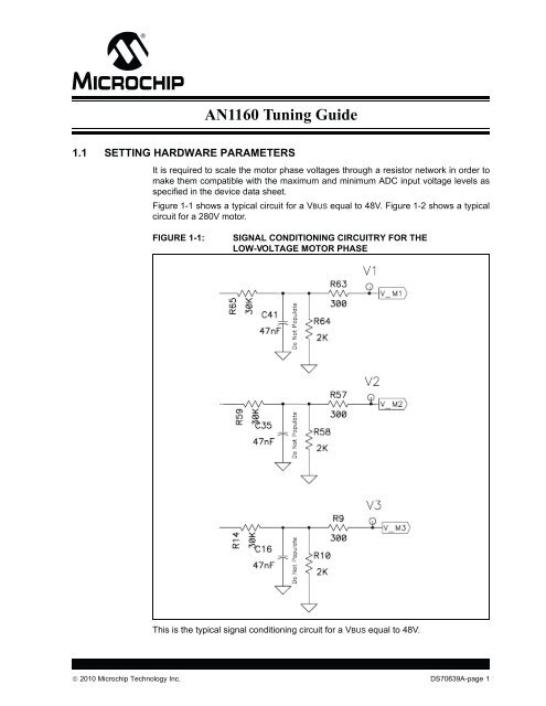
It is required to scale the motor phase voltages through a resistor network in order to<br />
make them compatible with the maximum and minimum ADC input voltage levels as<br />
specified in the device data sheet.<br />
Figure 1-1 shows a typical circuit for a VBUS equal to 48V. Figure 1-2 shows a typical<br />
circuit for a 280V motor.<br />
FIGURE 1-1: SIGNAL CONDITIONING CIRCUITRY FOR THE<br />
LOW-VOLTAGE MOTOR PHASE<br />
This is the typical signal conditioning circuit for a VBUS equal to 48V.<br />
2010 <strong>Microchip</strong> Technology Inc. DS70639A-page 1
FIGURE 1-2: SIGNAL CONDITIONING CIRCUITRY FOR THE HIGH-VOLTAGE MOTOR PHASE<br />
This is the typical signal conditioning circuit for a VBUS equal to 400V.<br />
It is required to sample the motor voltage phase signals simultaneously; therefore, they<br />
have to be connected to ADC input pins in which the CH1, CH2, CH3 sample and hold<br />
circuits can be used. These channels can be AN0, AN1, AN2 or AN3, AN4 and AN5.<br />
1.2 SOFTWARE PARAMETERS<br />
All of the configurable parameters are defined in the UserParameters.h file. The<br />
parameters are classified into three different categories: basic, advance, and derived.<br />
Figure 1-3 shows these parameters and Table 1-1 provides descriptions of each<br />
parameter.<br />
DS70639A-page 2 2010 <strong>Microchip</strong> Technology Inc.
FIGURE 1-3: SOFTWARE PARAMETERS<br />
<strong>AN1160</strong> <strong>Tuning</strong> <strong>Guide</strong><br />
2010 <strong>Microchip</strong> Technology Inc. DS70639A-page 3
TABLE 1-1: SOFTWARE PARAMETER DESCRIPTIONS<br />
Software Parameter Description<br />
DESIRED_MIPS This macro defines the operating MIPS of the dsPIC device.<br />
FIN This macro defines the input clock frequency utilized by the system<br />
clock circuitry.<br />
XTAL If this macro is defined, the dsPIC device utilizes an external crystal<br />
as the source for the input clock. The FRC clock is selected when this<br />
macro is not defined.<br />
PWM_FREQUENCY This macro sets the output frequency of the PWM module.<br />
MAX_PWM_TICKS This macro sets the number of pulses applied in the forced commutation<br />
process utilized for breaking the motor’s stand-still inertia. The<br />
possible value could be from 1 to 65535. This value is set according<br />
to the motor and load characteristics.<br />
RAMP_UP_DELAY This macro sets the delay required to switch from the forced commutation<br />
mode to sensorless mode. This delay is useful when the motor<br />
is attached to high-inertia loads such as fans with large blades.<br />
MAX_DUTY_CYCLE_PERCENTAGE This macro limits the maximum PWM duty cycle. It is expressed in<br />
PWM cycles.<br />
MIN_DUTY_CYCLE_PERCENTAGE This macro sets the duty cycle for the start-up sequence. It is defined<br />
in PWM cycles. Once the motor is running this number also limits the<br />
minimum duty cycle that can be applied to the motor.<br />
CLOSELOOPMODE When defined, this macro enables the speed controller. If it is disabled,<br />
the motor will run without the speed controller.<br />
PROPORTIONAL_GAIN This macro sets the P gain for the speed PID controller.<br />
INTEGRAL_GAIN This macro sets the I gain for the speed PID controller.<br />
PHASE_ADVANCE_DEGREES Phase advance angles to get the best motor performance or surpass<br />
the nominal speed.<br />
BLANKING_COUNT Sets the blanking count expressed in PWM cycles used to avoid false<br />
zero-crossing detection.<br />
S3 This macro defines the I/O port used to poll the push button S3.<br />
S2 This macro defines the I/O port used to poll the push button S2.<br />
DS70639A-page 4 2010 <strong>Microchip</strong> Technology Inc.
1.3 SETTING START-UP PARAMETERS<br />
<strong>AN1160</strong> <strong>Tuning</strong> <strong>Guide</strong><br />
In order to determine the start-up parameters it is required to follow the described<br />
procedure.<br />
1. Disable the speed loop controller. It is possible to disable this controller by<br />
removing the CLOSELOOPMODE definition. If DMCI with RTDM is used to<br />
control the motor, make sure the “ENABLE PI” button is OFF.<br />
2. Set the reference speed (using the pot or the DMCI slider, depending on which SW<br />
version is running), “maximum PWM ticks”, “Phase Advance”, and “ramp up delay”<br />
values to 0. Set “Blanking Count” to 5.<br />
3. Next, we are going to determine the correct values for “minimum duty cycle” and<br />
“maximum PWM ticks”. This is a trial-and-error process that depends on the motor<br />
and load characteristics.<br />
4. Turn the motor ON by pressing S2 (non-DMCI version) or by turning ON the<br />
START/STOP button on DMCI.<br />
5. Slowly increase (steps equal to 10 units) the “maximum PWM ticks” value. Stop<br />
increasing the “maximum PWM ticks” value when the motor shaft starts bouncing<br />
backward and forward.<br />
6. If the motor shaft is not bouncing backward and forward, but instead is emitting a<br />
high-pitched sound, increase the “minimum duty cycle” by 10 unit steps and repeat<br />
steps 4-6 until the motor shaft is bouncing backward and forward.<br />
7. The value “minimum PWM duty cycle” is close to the correct the start-up value<br />
when the motor shaft is bouncing back and forward. At this point it is required to<br />
find the minimum duty cycle in order to completely break the stand-still inertia.<br />
8. Increase (using one step at a time) the “minimum PWM duty cycle”, and stop when<br />
the motor is continuously spinning.<br />
9. Save the current “minimum PWM duty cycle” and “maximum PWM ticks”.<br />
10. Stop the motor.<br />
11. Start the motor using the saved “minimum PWM duty cycle” and “maximum PWM<br />
ticks” for the start-up sequence. The motor should be running.<br />
Note: In some applications where high-inertia loads are attached to the motor is<br />
required to use a delay allowing the software make a smooth transition from<br />
the start-up sequence to sensorless mode. This delay is set by the<br />
“ramp-up delay” value. Increase or decrease this value as required by the<br />
application, specifically when the motor shaft it is not bouncing after trying<br />
different combinations of “minimum PWM duty cycle” and “maximum PWM<br />
ticks” values.<br />
Figure 1-4 shows the start-up tuning procedure flow chart<br />
2010 <strong>Microchip</strong> Technology Inc. DS70639A-page 5
FIGURE 1-4: TUNING PROCEDURE FOR THE START-UP SEQUENCE<br />
Increase<br />
MIN_DUTY_CYCLE<br />
Disable Close<br />
Loop Controller<br />
(Speed Controller)<br />
RAMP_UP_DELAY = 0<br />
MIN_DUTY_CYCLE_PERCENTAGE = 10<br />
MAX_PWM_TICKS = 0<br />
PHASE_ADVANCE_DEGREES = 0<br />
BLANKING COUNT = 5<br />
Start Motor<br />
Increase<br />
MAX_PWM_TICKS<br />
Is the motor shaft bouncing<br />
back and forward?<br />
(~every 500 mS)<br />
Increase<br />
MIN_DUTY_CYCLE_PERCENTAGE<br />
Is the motor running?<br />
DS70639A-page 6 2010 <strong>Microchip</strong> Technology Inc.<br />
YES<br />
Is the motor emitting a<br />
high-pitched sound?<br />
NO<br />
YES<br />
YES<br />
END<br />
NO<br />
NO
1.4 ADVANCE TUNING PARAMETERS<br />
<strong>AN1160</strong> <strong>Tuning</strong> <strong>Guide</strong><br />
The other tuning parameters such as the PI gains, the Phase Advance Angle, and the<br />
Blanking count number requires a better understanding of the algorithm used in the<br />
application note. Please refer to application note <strong>AN1160</strong> “Sensorless BLDC Control<br />
with Back-EMF Filtering Using a Majority Function”.<br />
<strong>Tuning</strong> the close loop gains P and I can be done using multiple methods. Please refer<br />
to Wikipedia and search for “PID controller” and go to the section “Loop <strong>Tuning</strong>” for<br />
more information, or use the following link to access the information directly:<br />
http://en.wikipedia.org/wiki/PID_controller#Loop_tuning<br />
It is possible to improve the performance of the algorithm by increasing the phase<br />
advance angle and the blanking counter. To do so, it is required to observe the current<br />
waveform using a current probe and a oscilloscope.<br />
1. Attached the current probe to any of the motor phases.<br />
2. Start the motor.<br />
3. Increase the motor speed slowly and stop at ¼ point of the maximum rated speed.<br />
4. Change the phase advance and blanking counter values in order to get the current<br />
waveform as close as possible to Figure 1-5 when full load is applied to the motor.<br />
5. Observe the current waveform while increasing the speed to ¼ of full speed.<br />
6. Repeat steps 4-5 until the motor reaches the maximum rated speed.<br />
7. The current waveform at this point should be similar in shape as Figure 1-5 in a<br />
wide speed range.<br />
FIGURE 1-5: DESIRED PHASE CURRENT WAVEFORM<br />
2010 <strong>Microchip</strong> Technology Inc. DS70639A-page 7
NOTES:<br />
DS70639A-page 8 2010 <strong>Microchip</strong> Technology Inc.
Note the following details of the code protection feature on <strong>Microchip</strong> devices:<br />
• <strong>Microchip</strong> products meet the specification contained in their particular <strong>Microchip</strong> Data Sheet.<br />
• <strong>Microchip</strong> believes that its family of products is one of the most secure families of its kind on the market today, when used in the<br />
intended manner and under normal conditions.<br />
• There are dishonest and possibly illegal methods used to breach the code protection feature. All of these methods, to our<br />
knowledge, require using the <strong>Microchip</strong> products in a manner outside the operating specifications contained in <strong>Microchip</strong>’s Data<br />
Sheets. Most likely, the person doing so is engaged in theft of intellectual property.<br />
• <strong>Microchip</strong> is willing to work with the customer who is concerned about the integrity of their code.<br />
• Neither <strong>Microchip</strong> nor any other semiconductor manufacturer can guarantee the security of their code. Code protection does not<br />
mean that we are guaranteeing the product as “unbreakable.”<br />
Code protection is constantly evolving. We at <strong>Microchip</strong> are committed to continuously improving the code protection features of our<br />
products. Attempts to break <strong>Microchip</strong>’s code protection feature may be a violation of the Digital Millennium Copyright Act. If such acts<br />
allow unauthorized access to your software or other copyrighted work, you may have a right to sue for relief under that Act.<br />
Information contained in this publication regarding device<br />
applications and the like is provided only for your convenience<br />
and may be superseded by updates. It is your responsibility to<br />
ensure that your application meets with your specifications.<br />
MICROCHIP MAKES NO REPRESENTATIONS OR<br />
WARRANTIES OF ANY KIND WHETHER EXPRESS OR<br />
IMPLIED, WRITTEN OR ORAL, STATUTORY OR<br />
OTHERWISE, RELATED TO THE INFORMATION,<br />
INCLUDING BUT NOT LIMITED TO ITS CONDITION,<br />
QUALITY, PERFORMANCE, MERCHANTABILITY OR<br />
FITNESS FOR PURPOSE. <strong>Microchip</strong> disclaims all liability<br />
arising from this information and its use. Use of <strong>Microchip</strong><br />
devices in life support and/or safety applications is entirely at<br />
the buyer’s risk, and the buyer agrees to defend, indemnify and<br />
hold harmless <strong>Microchip</strong> from any and all damages, claims,<br />
suits, or expenses resulting from such use. No licenses are<br />
conveyed, implicitly or otherwise, under any <strong>Microchip</strong><br />
intellectual property rights.<br />
Trademarks<br />
The <strong>Microchip</strong> name and logo, the <strong>Microchip</strong> logo, dsPIC,<br />
KEELOQ, KEELOQ logo, MPLAB, PIC, PICmicro, PICSTART,<br />
PIC32 logo, rfPIC and UNI/O are registered trademarks of<br />
<strong>Microchip</strong> Technology Incorporated in the U.S.A. and other<br />
countries.<br />
FilterLab, Hampshire, HI-TECH C, Linear Active Thermistor,<br />
MXDEV, MXLAB, SEEVAL and The Embedded Control<br />
Solutions Company are registered trademarks of <strong>Microchip</strong><br />
Technology Incorporated in the U.S.A.<br />
Analog-for-the-Digital Age, Application Maestro, CodeGuard,<br />
dsPICDEM, dsPICDEM.net, dsPICworks, dsSPEAK, ECAN,<br />
ECONOMONITOR, FanSense, HI-TIDE, In-Circuit Serial<br />
Programming, ICSP, Mindi, MiWi, MPASM, MPLAB Certified<br />
logo, MPLIB, MPLINK, mTouch, Octopus, Omniscient Code<br />
Generation, PICC, PICC-18, PICDEM, PICDEM.net, PICkit,<br />
PICtail, REAL ICE, rfLAB, Select Mode, Total Endurance,<br />
TSHARC, UniWinDriver, WiperLock and ZENA are<br />
trademarks of <strong>Microchip</strong> Technology Incorporated in the<br />
U.S.A. and other countries.<br />
SQTP is a service mark of <strong>Microchip</strong> Technology Incorporated<br />
in the U.S.A.<br />
All other trademarks mentioned herein are property of their<br />
respective companies.<br />
© 2010, <strong>Microchip</strong> Technology Incorporated, Printed in the<br />
U.S.A., All Rights Reserved.<br />
Printed on recycled paper.<br />
ISBN: 978-1-60932-342-4<br />
<strong>Microchip</strong> received ISO/TS-16949:2002 certification for its worldwide<br />
headquarters, design and wafer fabrication facilities in Chandler and<br />
Tempe, Arizona; Gresham, Oregon and design centers in California<br />
and India. The Company’s quality system processes and procedures<br />
are for its PIC ® MCUs and dsPIC ® DSCs, KEELOQ ® code hopping<br />
devices, Serial EEPROMs, microperipherals, nonvolatile memory and<br />
analog products. In addition, <strong>Microchip</strong>’s quality system for the design<br />
and manufacture of development systems is ISO 9001:2000 certified.<br />
2010 <strong>Microchip</strong> Technology Inc. DS70639A-page 9
AMERICAS<br />
Corporate Office<br />
2355 West Chandler Blvd.<br />
Chandler, AZ 85224-6199<br />
Tel: 480-792-7200<br />
Fax: 480-792-7277<br />
Technical Support:<br />
http://support.microchip.com<br />
Web Address:<br />
www.microchip.com<br />
Atlanta<br />
Duluth, GA<br />
Tel: 678-957-9614<br />
Fax: 678-957-1455<br />
Boston<br />
Westborough, MA<br />
Tel: 774-760-0087<br />
Fax: 774-760-0088<br />
Chicago<br />
Itasca, IL<br />
Tel: 630-285-0071<br />
Fax: 630-285-0075<br />
Cleveland<br />
Independence, OH<br />
Tel: 216-447-0464<br />
Fax: 216-447-0643<br />
Dallas<br />
Addison, TX<br />
Tel: 972-818-7423<br />
Fax: 972-818-2924<br />
Detroit<br />
Farmington Hills, MI<br />
Tel: 248-538-2250<br />
Fax: 248-538-2260<br />
Kokomo<br />
Kokomo, IN<br />
Tel: 765-864-8360<br />
Fax: 765-864-8387<br />
Los Angeles<br />
Mission Viejo, CA<br />
Tel: 949-462-9523<br />
Fax: 949-462-9608<br />
Santa Clara<br />
Santa Clara, CA<br />
Tel: 408-961-6444<br />
Fax: 408-961-6445<br />
Toronto<br />
Mississauga, Ontario,<br />
Canada<br />
Tel: 905-673-0699<br />
Fax: 905-673-6509<br />
WORLDWIDE SALES AND SERVICE<br />
ASIA/PACIFIC<br />
Asia Pacific Office<br />
Suites 3707-14, 37th Floor<br />
Tower 6, The Gateway<br />
Harbour City, Kowloon<br />
Hong Kong<br />
Tel: 852-2401-1200<br />
Fax: 852-2401-3431<br />
Australia - Sydney<br />
Tel: 61-2-9868-6733<br />
Fax: 61-2-9868-6755<br />
China - Beijing<br />
Tel: 86-10-8528-2100<br />
Fax: 86-10-8528-2104<br />
China - Chengdu<br />
Tel: 86-28-8665-5511<br />
Fax: 86-28-8665-7889<br />
China - Chongqing<br />
Tel: 86-23-8980-9588<br />
Fax: 86-23-8980-9500<br />
China - Hong Kong SAR<br />
Tel: 852-2401-1200<br />
Fax: 852-2401-3431<br />
China - Nanjing<br />
Tel: 86-25-8473-2460<br />
Fax: 86-25-8473-2470<br />
China - Qingdao<br />
Tel: 86-532-8502-7355<br />
Fax: 86-532-8502-7205<br />
China - Shanghai<br />
Tel: 86-21-5407-5533<br />
Fax: 86-21-5407-5066<br />
China - Shenyang<br />
Tel: 86-24-2334-2829<br />
Fax: 86-24-2334-2393<br />
China - Shenzhen<br />
Tel: 86-755-8203-2660<br />
Fax: 86-755-8203-1760<br />
China - Wuhan<br />
Tel: 86-27-5980-5300<br />
Fax: 86-27-5980-5118<br />
China - Xian<br />
Tel: 86-29-8833-7252<br />
Fax: 86-29-8833-7256<br />
China - Xiamen<br />
Tel: 86-592-2388138<br />
Fax: 86-592-2388130<br />
China - Zhuhai<br />
Tel: 86-756-3210040<br />
Fax: 86-756-3210049<br />
ASIA/PACIFIC<br />
India - Bangalore<br />
Tel: 91-80-3090-4444<br />
Fax: 91-80-3090-4123<br />
India - New Delhi<br />
Tel: 91-11-4160-8631<br />
Fax: 91-11-4160-8632<br />
India - Pune<br />
Tel: 91-20-2566-1512<br />
Fax: 91-20-2566-1513<br />
Japan - Yokohama<br />
Tel: 81-45-471- 6166<br />
Fax: 81-45-471-6122<br />
Korea - Daegu<br />
Tel: 82-53-744-4301<br />
Fax: 82-53-744-4302<br />
Korea - Seoul<br />
Tel: 82-2-554-7200<br />
Fax: 82-2-558-5932 or<br />
82-2-558-5934<br />
Malaysia - Kuala Lumpur<br />
Tel: 60-3-6201-9857<br />
Fax: 60-3-6201-9859<br />
Malaysia - Penang<br />
Tel: 60-4-227-8870<br />
Fax: 60-4-227-4068<br />
Philippines - Manila<br />
Tel: 63-2-634-9065<br />
Fax: 63-2-634-9069<br />
Singapore<br />
Tel: 65-6334-8870<br />
Fax: 65-6334-8850<br />
Taiwan - Hsin Chu<br />
Tel: 886-3-6578-300<br />
Fax: 886-3-6578-370<br />
Taiwan - Kaohsiung<br />
Tel: 886-7-536-4818<br />
Fax: 886-7-536-4803<br />
Taiwan - Taipei<br />
Tel: 886-2-2500-6610<br />
Fax: 886-2-2508-0102<br />
Thailand - Bangkok<br />
Tel: 66-2-694-1351<br />
Fax: 66-2-694-1350<br />
EUROPE<br />
Austria - Wels<br />
Tel: 43-7242-2244-39<br />
Fax: 43-7242-2244-393<br />
Denmark - Copenhagen<br />
Tel: 45-4450-2828<br />
Fax: 45-4485-2829<br />
France - Paris<br />
Tel: 33-1-69-53-63-20<br />
Fax: 33-1-69-30-90-79<br />
Germany - Munich<br />
Tel: 49-89-627-144-0<br />
Fax: 49-89-627-144-44<br />
Italy - Milan<br />
Tel: 39-0331-742611<br />
Fax: 39-0331-466781<br />
Netherlands - Drunen<br />
Tel: 31-416-690399<br />
Fax: 31-416-690340<br />
Spain - Madrid<br />
Tel: 34-91-708-08-90<br />
Fax: 34-91-708-08-91<br />
UK - Wokingham<br />
Tel: 44-118-921-5869<br />
Fax: 44-118-921-5820<br />
01/05/10<br />
DS70639A-page 10 2010 <strong>Microchip</strong> Technology Inc.


