SEQUENTIAL HIGH-VOLUME SAMPLER CAV-A/MSb
SEQUENTIAL HIGH-VOLUME SAMPLER CAV-A/MSb
SEQUENTIAL HIGH-VOLUME SAMPLER CAV-A/MSb

Create successful ePaper yourself
Turn your PDF publications into a flip-book with our unique Google optimized e-Paper software.
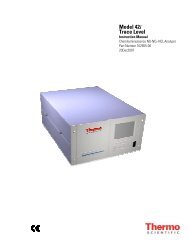
<strong>SEQUENTIAL</strong><br />
<strong>HIGH</strong>-<strong>VOLUME</strong> <strong>SAMPLER</strong><br />
<strong>CAV</strong>-A/<strong>MSb</strong><br />
- MASS FLOW CONTROL –<br />
AUTOVÍA A- II, KM.575 - 08293 COLLBATÓ – BARCELONA - T.93 777 05 00 / F.93 777 05 50- www.mcvsa.com
High-Volume Sampler <strong>CAV</strong>-A/<strong>MSb</strong>. User and Technical Manual. Version V1.01<br />
______________________________________________________________<br />
<strong>SEQUENTIAL</strong> <strong>HIGH</strong>-<strong>VOLUME</strong> <strong>SAMPLER</strong><br />
<strong>CAV</strong>-A/<strong>MSb</strong><br />
USER AND TECHNICAL<br />
MANUAL<br />
Version 1.01<br />
This manual must be carefully read before making any attempt to switch the<br />
equipment on. If you have any doubts, please contact your supplier or the MCV,<br />
S.A. Technical Service Department directly on the pone +34 93 777 0500, by FAX<br />
on +34 93 777 0550 or by E-mail to the following address sat@mcvsa.com<br />
September 2008<br />
______________________________________________________________<br />
MCV, SA
High-Volume Sampler <strong>CAV</strong>-A/<strong>MSb</strong>. User and Technical Manual. Version V1.01<br />
______________________________________________________________<br />
GUARANTEE<br />
MCV, S.A. guarantees the operation of the assembly of materials that make up the<br />
delivered equipment against any manufacturing defect, for a period of one year.<br />
All defects or faults, produced by incorrect use, impacts, over-voltages, incorrect<br />
power suppliers, lightning strikes to the network or data transmissions lines or<br />
handling and/or intervention by personal not authorized by MCV are excluded<br />
from this guarantee.<br />
Periodic equipment calibration, preventive maintenance operations and the<br />
replacing of parts due to normal wear are not covered by this guarantee.<br />
The application of this guarantee is subject to correct equipment installation and<br />
operation, together with correct maintenance in accordance with the contents of<br />
this manual.<br />
This guarantee includes both the materials and labour that are required to repair the<br />
equipment, with the customer being responsible for any costs involved in the<br />
moving or transport of the equipment.<br />
NOTE<br />
MCV S.A. reserves the right to incorporate all modifications it thinks fit in order<br />
to improve the performance of the Sampler without any prior warning.<br />
______________________________________________________________<br />
MCV, SA
High-Volume Sampler <strong>CAV</strong>-A/<strong>MSb</strong>. User and Technical Manual. Version V1.01<br />
______________________________________________________________<br />
REVISION HISTORY<br />
MANUAL<br />
Date Version Description<br />
September 2008 1.01 It is the first version. It describes the software version V 1.10<br />
functionalities.<br />
SOFTWARE<br />
Date Version Description<br />
September 2008 1.10 It is the first version of the <strong>CAV</strong>-A/Mb Sampler.<br />
______________________________________________________________<br />
MCV, SA
High-Volume Sampler <strong>CAV</strong>-A/<strong>MSb</strong>. User and Technical Manual. Version V1.01<br />
______________________________________________________________<br />
1. INTRODUCTION 1<br />
2. <strong>SAMPLER</strong> DESCRIPTION 3<br />
3. TECHNICAL SPECIFICATIONS 5<br />
3.1. DIMENSIONS AND WEIGHTS 5<br />
3.2. ELECTRICAL SPECIFICATIONS 5<br />
3.3. OPERATIONAL SPECIFICATIONS 5<br />
4. INSTALATION AND SETUP 7<br />
5. USING THE <strong>SAMPLER</strong> 9<br />
5.1. KEYPAD DESCRIPTION 9<br />
5.2. <strong>SAMPLER</strong> MENUS 9<br />
5.2.1. Main Menu 9<br />
5.2.2. Operating 9<br />
5.2.3. Summary Filters 11<br />
5.2.4. Printing summary 11<br />
5.2.5. Sampler Configuration 11<br />
5.2.6. Cycle configuration 13<br />
5.2.6.1. Examples of deferred start-up and continuous sampling 14<br />
5.2.6.2. Examples of deferred start-up and discontinuous sampling 15<br />
5.2.7. Sampler Supervision 17<br />
5.2.8. Maintenance 18<br />
5.2.8.1. Calibration 18<br />
5.2.8.2. Electrical Adjusting 21<br />
5.2.8.3. Messages 22<br />
5.2.8.3. Test 23<br />
5.2.8.4. Cycle Stop/Continue 23<br />
______________________________________________________________<br />
MCV, SA
High-Volume Sampler <strong>CAV</strong>-A/<strong>MSb</strong>. User and Technical Manual. Version V1.01<br />
______________________________________________________________<br />
5.2.8.5. Paper advance 24<br />
5.2.9. Immediate Start-up 24<br />
5.2.10. Deferred Start-up 24<br />
5.2.11. Filter Stop/Charge 24<br />
5.3. USING THE <strong>SAMPLER</strong> 25<br />
6. FILTER HOLDER 27<br />
7. MAINTENANCE 29<br />
7.1. CHANGING PAPER AND RIBBON 29<br />
8. TECHNICAL INFORMATION 31<br />
8.1. PROTECTIONS AND FUSES 31<br />
8.2. CONTROL BOARD / POWER BOARD 31<br />
8.3. DISPLAY BOARD 32<br />
8.4. CONNECTORS 32<br />
8.4.1. 230Vac power supply connector 32<br />
8.4.2. Power board connector 32<br />
8.4.2.1. Power board connector J1. side Motor 32<br />
8.4.2.2. Power board connector J2. Filter Motor 33<br />
8.4.2.3. Power board connector J3. Loading Motor 33<br />
8.4.2.4. Power board connector J4. Position Detector 33<br />
8.4.2.5. Power board connector J5. Exterior/Outer transformer 34<br />
8.4.2.6. Power board connector J6. Inlet 230Vac 34<br />
8.4.2.7. Power board connector J7. Outer/Exterior Check (optional) 34<br />
8.4.2.8. Control board connector J8. Motor 35<br />
8.4.2.9. Power board connector J9. Fluorescent light 35<br />
8.4.2.10. Power board connector J10. Switch / Battery 35<br />
______________________________________________________________<br />
MCV, SA
High-Volume Sampler <strong>CAV</strong>-A/<strong>MSb</strong>. User and Technical Manual. Version V1.01<br />
______________________________________________________________<br />
8.4.2.11. Power board connector JP1. Power board and control board<br />
Interconnection 36<br />
8.4.3. Control board connectors 37<br />
8.4.3.1. Control board connectors JP1. Printer module 37<br />
8.4.3.2. Control board connectors JP2. Keypad / Display module 38<br />
8.4.3.3. Control board connectors JP3. Boards Interconnection 38<br />
8.4.3.4. Control board connectors JT1 y JT2. Temperature sensors 39<br />
8.4.3.5. JRS connector. Serial communications. 39<br />
8.5. SPARE PARTS 39<br />
9 DRAWINGS 41<br />
______________________________________________________________<br />
MCV, SA
High-Volume Sampler <strong>CAV</strong>-A/<strong>MSb</strong>. User and Technical Manual. Version V1.01<br />
______________________________________________________________<br />
1. INTRODUCTION<br />
The purpose of this manual is to help the user become familiar with installing the<br />
Sampler, setting up, using and maintaining it. It is strongly recommended to read<br />
this manual before installing or using the Sampler.<br />
The Sequential High-Volume Sampler with Mass Flow Control and a capacity for<br />
15 filters of 15 cm of diameter, has the main application in the determination of<br />
suspended particles, a normal parameter in atmospheric quality studies in locations<br />
that require little maintenance.<br />
The Sampler incorporates a new motor container which considerably reduces the<br />
noise.<br />
The Sampler main features are:<br />
- Capacity for 15 filters of 15 cm of diameter.<br />
- Low noise level (less than 40dB at 30m 3 /h)<br />
- Wide operating range without equipment recalibration being necessary<br />
- No recalibration needed depending on the site<br />
- True or standardized flow rate control<br />
- Working cycle between an hour and a week, which can be easily set by user<br />
- Operating cycle duration configured by user, between clock hours and<br />
motor hours<br />
- Enhanced sampling rate stability (better than 1.5%)<br />
- Warning SMS messages<br />
The <strong>CAV</strong>-A/<strong>MSb</strong> Sampler meets the specific requirements for particulate matter<br />
sensors contained in the UNE-EN 12341 and UNE-EN 14907.<br />
For flow measurement, the equipment follows the recommendations of the UNE-<br />
EN 5167.<br />
The unit is supplied in a recyclable wood package, which complies with<br />
International Plant Health Protection Regulations set out in document ISPM 15.<br />
______________________________________________________________<br />
MCV, SA 1
High-Volume Sampler <strong>CAV</strong>-A/<strong>MSb</strong>. User and Technical Manual. Version V1.01<br />
______________________________________________________________<br />
______________________________________________________________<br />
MCV, SA 2
High-Volume Sampler <strong>CAV</strong>-A/<strong>MSb</strong>. User and Technical Manual. Version V1.01<br />
______________________________________________________________<br />
2. <strong>SAMPLER</strong> DESCRIPTION<br />
The high-volume Sampler <strong>CAV</strong>-A/M’S is a suspended particle Sampler which is<br />
used to study atmospheric contaminants. The sample is collected in a suitable filter<br />
in which the gravimetric and/or chemical evaluation of the retained particles is<br />
performed.<br />
The unit is built into a case made of weatherproof material and easy to transport so<br />
that the Sampler is able to operate without an extra environmental protection. The<br />
suction pump is powerful enough to work over a wide flow rate range and without<br />
any maintenance.<br />
The Sampler includes an automatic electronic control that keeps the settled airflow<br />
independently of the clogging level in the sampling filter, mains variations and<br />
pressure and ambient temperature variations.<br />
NOTE: the airflow can be constant and the same as the airflow programmed<br />
whenever dogging is not excessive, and also depending on the filter’s material. In<br />
general, there is not any problem when using flow rates of 30m 3 /h, 24 hours<br />
sampling duration and GF/A or QMA Whatman filter. Contact to MCV,S.A., to<br />
use another kind of filters.<br />
Airflow measurement is made by means of a calibrated orifice, three pressure<br />
sensors and two temperature sensors. The pressure sensors are used to determine<br />
the pressure fall in the calibrated orifice, the absolute pressure at the orifice<br />
entrance and the ambient absolute pressure. The temperature sensors are used to<br />
measure the sample temperature and the temperature inside the Sampler in order to<br />
carry out corrections if these are necessary. The Sampler temperature sensor is set<br />
in the diaphragm, after the sampling filter.<br />
All values and parameters for operation, sampling and calibration are displayed in<br />
the large LCD screen, along with the most important data items, such as current<br />
flow rate and total accumulated volume, which are displayed using large<br />
characters.<br />
The four keys on the unit’s front control panel are used to execute all operations of<br />
Sampler usage, configuration and calibration.<br />
The Sampler includes a battery in order to operate in case of power failure.<br />
However, if the Sampler is running on battery, it can not sample. The Sampler has<br />
______________________________________________________________<br />
MCV, SA<br />
3
High-Volume Sampler <strong>CAV</strong>-A/<strong>MSb</strong>. User and Technical Manual. Version V1.01<br />
______________________________________________________________<br />
a board that includes the power supply, the battery charge control and the power<br />
electronics of the motor filter change system. Another two boards, fixed to the<br />
equipment frontal, include all the digital electronic system, the display and the<br />
keypad.<br />
Filter changing system is composed by a motor charger, a side motor and a filter<br />
motor. The first one prepares the suitable filter holder so the side motor places it<br />
laterally to the filter motor, which will put the filter holder in operation position.<br />
______________________________________________________________<br />
MCV, SA<br />
4
High-Volume Sampler <strong>CAV</strong>-A/<strong>MSb</strong>. User and Technical Manual. Version V1.01<br />
______________________________________________________________<br />
3. TECHNICAL SPECIFICATIONS<br />
3.1. DIMENSIONS AND WEIGHTS<br />
The Sampler’s dimensions and weight (without the filter holder head) are as<br />
follows:<br />
Width 84 cm.<br />
Depth 60 cm.<br />
Height 112 cm.<br />
Weight 62 Kg<br />
The equipment is supplied in a recyclable wooden box measuring 89x65x117 cm<br />
which has a weight of 31 Kg. This package meets the International Plant Health<br />
Protection Regulations set out in document ISPM 15.<br />
3.2. ELECTRICAL SPECIFICATIONS<br />
Power supply input 230Vac single-phase<br />
Maximum power 1000 VA<br />
Circuit breaker Bipolar, 6A<br />
Internal fuses 230Vac (F1 and F2) 5x20, fast, 5A<br />
Internal fuses 12Vcc (F3 and F4) 5x20, fast, 3A and 2A<br />
3.3. OPERATIONAL SPECIFICATIONS<br />
Filter capacity Maximum 15 filter of 15 cm<br />
Flow rate range Configurable from 15 to 45 m 3 /h<br />
Flow rate programmer resolution 0,5 m 3 /h<br />
Flow rate control True or normalized (configurable)<br />
Internal flow rate measurement<br />
0,01 m 3 /h<br />
resolution<br />
Expanded uncertainty
High-Volume Sampler <strong>CAV</strong>-A/<strong>MSb</strong>. User and Technical Manual. Version V1.01<br />
______________________________________________________________<br />
(1) The battery is incorporated so that the Sampler can be configured (no<br />
sampling) without any extra power supply; no data is lost if the<br />
equipment runs out of battery. The Sampler can sample without a battery<br />
or when it is flat, if it is connected to 230 Vac.<br />
(2) Laboratory conditions.<br />
______________________________________________________________<br />
MCV, SA<br />
6
High-Volume Sampler <strong>CAV</strong>-A/<strong>MSb</strong>. User and Technical Manual. Version V1.01<br />
______________________________________________________________<br />
4. INSTALLATION AND SET UP<br />
The installation of the <strong>CAV</strong>-A/M Sampler does not require any special form of<br />
conditioning, only a mains socket providing 230 Vac with a minimum power of<br />
1100 W.<br />
The Sampler box is made of polyester fiber, which is able to withstand the<br />
environmental conditions found throughout Spain during all seasons of the year.<br />
When working in areas with strong winds, it is recommended to suitably hold the<br />
Sampler by some means to prevent it from being blown over. Normally, the feet<br />
are fixed to the ground using plastic or metal clamps. If the ground is soil, then the<br />
Sampler can be positioned on the top of a concrete slab measuring (70x60x10 cm).<br />
In order to assure the good changing filter system operation, it is important to place<br />
the Sampler in a flat area.<br />
If the Sampler has to be installed inside a building, MCV,S.A. can supply<br />
additional tube to connect the Sampler and the holder filter, both rigid and flexible<br />
material.<br />
It is recommended to install the Sampler output tube, which is supplied with the<br />
unit. This tube reduces noise to a certain extent and prevents possible feedback of<br />
air from Sampler air outlet to the filter holder inlet. A stainless steel clamp is<br />
supplied with the three-meter exhaust hose for holding this same hose to the air<br />
outlet dome on the Sampler.<br />
Regarding the installation conditions (sampling height, distance to nearby<br />
disturbing accidents, etc), the rules recommended by the various competent<br />
national and international organizations should be followed.<br />
The Sampler is supplied with a three-meter long electric mains cable (however, it<br />
can be optionally supplied with other lengths), which must be connected to the<br />
equipment and to 230-V single-phase mains socket with ground connection. It is<br />
highly recommended to check this point carefully because one of the most<br />
common causes of failure is connecting it to 380 Vac. This mains socket must be<br />
suitable protected against inclement weather.<br />
Once the equipment has been connected to the mains supply, the breaker should be<br />
reset and the Sampler’s ON/OFF switch set to ON. Now, the Sampler is ready for<br />
use. However, before performing any sampling, make sure that the Sampler’s<br />
______________________________________________________________<br />
MCV, SA<br />
7
High-Volume Sampler <strong>CAV</strong>-A/<strong>MSb</strong>. User and Technical Manual. Version V1.01<br />
______________________________________________________________<br />
configurable parameters agree with your requirements (see the following section<br />
on how to configure the sampling parameters for the Sampler).<br />
______________________________________________________________<br />
MCV, SA<br />
8
High-Volume Sampler <strong>CAV</strong>-A/<strong>MSb</strong>. User and Technical Manual. Version V1.01<br />
______________________________________________________________<br />
5. USING THE <strong>SAMPLER</strong><br />
5.1. KEYPAD DESCRIPTION<br />
The keypad is used to access all the Sampler functions, all the sampling<br />
parameters, the operating cycle configuration and the Sampler calibration<br />
parameters. This keypad consists of the following four keys: ↑, ↓, ↵ and ←.<br />
The first two keys ↑ and ↓, are used to move up and down through the menus with<br />
this possibility, or to vary the value at the moment being programmed. The ↵ key<br />
is used to select the desired option or to validate the entry made with ↑ and ↓. The<br />
← key is used to move to the previous menu or to exit the programming of the<br />
current value, but without validating the values, recovering the original value.<br />
When displaying a screen with selection options or where values can be<br />
configured, the selected option or values will be displayed in REVERSE VIDEO.<br />
5.2. <strong>SAMPLER</strong> MENUS<br />
The descriptions of Sampler screens or options provided below correspond to the<br />
current program version, V1.10. Therefore, there may be some small differences<br />
between the description given and what is actually seen on the Sampler screen<br />
when using a different program version.<br />
5.2.1. Main menu<br />
With this screen and the associated keys, all the Sampler’s functions and options<br />
can be accessed.<br />
5.2.2. Operating<br />
Every time the Sampler is switched on the operation screen is displayed. This<br />
screen shows the current date and time, the instantaneous flow rate value, the<br />
present filter, the accumulated volume in the current cycle or last cycle performed,<br />
the selected flow rate, the total number of cubic meters sampled, together with the<br />
status of the equipment and the power supply. The installed version in the Sampler<br />
can also be seen. The Flow Rate and Volume parameters are displayed with a large<br />
character set so that they are more legible. The corresponding units are shown next<br />
______________________________________________________________<br />
MCV, SA<br />
9
High-Volume Sampler <strong>CAV</strong>-A/<strong>MSb</strong>. User and Technical Manual. Version V1.01<br />
______________________________________________________________<br />
to these parameters and also the Programmed Flow Rate and Accumulated figure;<br />
here an “N” will be displayed or not, depending on whether the unit is working<br />
with normalized flow rate or real.<br />
The possible Sampler states are listed below:<br />
- Cycle COMPLETED: the Sampler indicates that the cycle has been<br />
completed.<br />
- SAMPLE: the Sampler is sampling air.<br />
- AUTO ZERO: the Sampler is performing an automatic zeroing of the<br />
differential pressure sensors. This state lasts approximately 20 seconds and<br />
is repeated at a maximum rate of once per hour, and at minimum of once<br />
every six hours.<br />
- MAINS Failure: the Sampler should be sampling, but there is no mains<br />
power.<br />
- POSITION PLACING: The Sampler is placing the holder filter in the<br />
suitable position.<br />
- In STANDBY: a deferred start-up has been programmed, and the motor<br />
should not be running at this time.<br />
- FLOW RATE Alarm: the Sampler has detected a flow rate of less than 10<br />
m 3 /h over ten consecutive seconds and has shutdown the blower to protect<br />
it.<br />
- System Alarm: the Sampler has detected a system error.<br />
With respect to the power supply message, the two possibilities are:<br />
- Correct: the Sampler detects correct power supply levels.<br />
- MAINS FAILURE: the Sampler detects no mains power.<br />
Due to the fact that no parameters can be modified on this screen nor are there any<br />
selectable options, the ↑, ↓, ↵ keys do not have any function and only the ← key<br />
can be used to move to the main menu.<br />
______________________________________________________________<br />
MCV, SA<br />
10
High-Volume Sampler <strong>CAV</strong>-A/<strong>MSb</strong>. User and Technical Manual. Version V1.01<br />
______________________________________________________________<br />
5.2.3. Summary Filters<br />
This screen is used to display the current values of the sampled filters. The<br />
displayed values are:<br />
- Start sampling date and time.<br />
- Real and normalized volumes of the filter.<br />
- Temperature and average pressure of time the filter has been sampled.<br />
- Filter time and power failure for this filter.<br />
It is only possible to display information from three filter together; if there were<br />
more filters, this information can be displayed with the ↑ and ↓.<br />
5.2.4. Printing summary<br />
This option is a complement of the previous screen; it allows the printing of the<br />
sampled filter information.<br />
5.2.5. Sampler configuration<br />
This screen is used to display and modify the most frequently employed Sampler<br />
parameters, together with the sampling cycle. The configurable parameters are:<br />
- Operating Flow Rate (m 3 /h): the flow rate at which the Sampler aspirates<br />
in the sample. This value will be changed by 0,5m 3 /h using the ↑ or ↓ keys.<br />
The displayed value will change faster if one of the keys is maintained<br />
pressed. Pressing ↵ will confirm the new value, or the ← can be used to<br />
leave the previous value unchanged.<br />
- Control by Flow Rate: this is used to select whether the Sampler is going<br />
to regulate the previously selected flow rate, by means of the Normalized<br />
or Real value.<br />
- Cycle Duration (h): allows the sampling cycle duration to be varied<br />
between 1 and 168.<br />
______________________________________________________________<br />
MCV, SA<br />
11
High-Volume Sampler <strong>CAV</strong>-A/<strong>MSb</strong>. User and Technical Manual. Version V1.01<br />
______________________________________________________________<br />
- Filter Hours: it allows to select if the cycle hours, configured in Cycle<br />
Duration, are Motor or Clock hours. If Clock is selected, the cycle will<br />
fnish after the number of hours that the user has configured on the<br />
Sampler’s clock. This option is useful when the sampling is to be carried out<br />
in natural days or periods. If the Sampler is set in operation at 08:00, with a<br />
program length of 24 hours, then the cycle will be completed at 08:00 the<br />
following day. However, if mains failures occurred during this time, the<br />
total number of cubic meters will be less than those expected.<br />
If, on the other hand, Motor is selected, this means that the Sampler is to<br />
perform complete samples, with the motor hours indicated in Cycle<br />
Duration. If there are any power failures in this case, the cycle will not be<br />
completed within the expected number of hours, but instead, the period of<br />
time will be extended by the amount of time during which there was no<br />
mains power. This method has the advantage of always producing samples<br />
with the desired cubic meters, but if there are mains failures, the exact<br />
period during which the Sampler was operating will be unknown.<br />
- Normalization Temperature (°C): this allows the selection of the<br />
temperature that is to be employed in calculating the normalized flow rates<br />
and volume. It can be set from 0 to 25°C in one-degree steps. The<br />
preselected value is 0°C.<br />
- Date: enables the Sampler’s current date to be modified. This parameter,<br />
together with Time, is essential if the Sampler is to be employed with<br />
Deferred Start-up (see point 5.2.8)<br />
- Time: used to adjust the Sampler time.<br />
- RS rate (bauds): it is used to select the serial communications (RS-232V)<br />
rate. It is possible to choose between 2400, 4800, 9600 and 19200 bauds. It<br />
is for Technical Service use.<br />
- Language: it allows choosing the language. In this version, it is possible to<br />
choose between Spanish (ES) or English (EN).<br />
- Active Screen (min): It allows selecting how much time the display will be<br />
lighted, since the last key-press. It can be configured from 5 to 240 minutes.<br />
5.2.6. Cycle Configuration<br />
______________________________________________________________<br />
MCV, SA<br />
12
High-Volume Sampler <strong>CAV</strong>-A/<strong>MSb</strong>. User and Technical Manual. Version V1.01<br />
______________________________________________________________<br />
On this screecn, the number of filters prepared for sampling can be configured as<br />
well as if it desired that the Sampler starts at a specific day and date, and then, if a<br />
discontinuous sampling is desired (the motor will be working for a certain period<br />
of time, and then stopped for another period of time). In order to be sure that the<br />
sampling will be carried out during the expected period, it is very important to<br />
check that the date and time displayed by the equipment are correct. Once the<br />
values for the start date, start time, running time and stop time have all been<br />
programmed, the sampling operation is started by selecting the option Deferred<br />
Start-up. The options displayed on this screen are as follows:<br />
- Charged filters: filter holder prepared and charged on the equipment. The<br />
sampling cycle will finish after sampling the number of filters indicated in<br />
this option.<br />
- Automatic printing: it shows if the information will be printed at the end<br />
of every sampling.<br />
- First filter: it shows the filter which the Sampler will start with.<br />
- Start day: this indicates how many days must pass before the equipment<br />
starts sampling. This value can be configured between +0 and +7. +0<br />
indicates that sampling will start today; +1 will start tomorrow, etc.<br />
- Start hour/minute: indicates the hour and minute when the sampling has to<br />
start.<br />
- RUNNING time (HH:MM): indicates how long the motor will be in<br />
operation once the sampling operation has started.<br />
- Stop time (HH:MM): indicates, once the running time has elapsed, how<br />
long the motor is going to be off.<br />
These last two options are used to make discontinuous sampling operations and<br />
can be selected in fractions of 30 minutes, from 30 minutes up to 96 hours. If only<br />
one sampling is to be carried out with deferred start-up then it is very important to<br />
leave Running time and Stop time configured with --:--.<br />
______________________________________________________________<br />
MCV, SA<br />
13
High-Volume Sampler <strong>CAV</strong>-A/<strong>MSb</strong>. User and Technical Manual. Version V1.01<br />
______________________________________________________________<br />
5.2.6.1. Examples of deferred start-up and continuous sampling<br />
Configured data:<br />
Current date and time 31/12/00 09:05<br />
Cycle duration 24 hours<br />
Filter hours Clock<br />
Start day +1<br />
Start hour/minute 08:00<br />
Running time --:--<br />
Stop time --:--<br />
The cycle will start on the 01/01/01 at 08:00 and will finish on 02/01/01 at 08:00.<br />
Configured data:<br />
Current date and time 31/12/00 09:05<br />
Filter duration 24 hours<br />
Cycle hours Clock<br />
Start day +2<br />
Start hour/minute 00:00<br />
Running time --:--<br />
Stop time --:--<br />
The cycle will start on the 02/01/01 at 00:00 and will finish on the 03/01/01 at<br />
00:00.<br />
Configured data:<br />
Current date and time 31/12/00 09:05<br />
Filter duration 24 hours<br />
Filter hours Clock<br />
Start day +0<br />
Start hour/minute 08:00<br />
Running time --:--<br />
Stop time --:--<br />
The cycle will start immediately and will finish on the 01/01/01 at 09:05.<br />
______________________________________________________________<br />
MCV, SA<br />
14
High-Volume Sampler <strong>CAV</strong>-A/<strong>MSb</strong>. User and Technical Manual. Version V1.01<br />
______________________________________________________________<br />
Configured data:<br />
Current date and time 31/12/00 09:05<br />
Filter duration 24 hours<br />
Filter hours Clock<br />
Start day +0<br />
Start hour/minute 10:00<br />
Running time --:--<br />
Stop time --:--<br />
The cycle will start on the 31/12/00 at 10:00 and will finish on the 01/01/01 at<br />
10:00.<br />
If in all these examples the Cycle hours were Motor hours, the cycle behavior<br />
would be the same, except that there was any mains power failure, in which case<br />
the cycle would end later.<br />
5.2.6.2. Examples of deferred start-up and discontinuous sampling<br />
Configured data:<br />
Current date and time 31/12/00 09:05<br />
Filter duration 24 hours<br />
Filter hours Clock<br />
Start Day +1<br />
Start hour/minute 10:00<br />
Running time 06:00<br />
Stop time 06:00<br />
The cycle starts on 01/01/01 at 10:00 and finishes on 02/01/01 at 10:00. The<br />
sampling intervals are:<br />
From 01/01/01 10:00 to 01/01/01 16:00 6 hours sampling<br />
From 01/01/01 16:00 to 01/01/01 22:00 6 hours inactive<br />
From 01/01/01 22:00 to 02/01/00 04:00 6 hours sampling<br />
From 02/01/01 04:00 to 02/01/01 10:00 6 hours inactive<br />
Configured data:<br />
______________________________________________________________<br />
MCV, SA<br />
15
High-Volume Sampler <strong>CAV</strong>-A/<strong>MSb</strong>. User and Technical Manual. Version V1.01<br />
______________________________________________________________<br />
Current date and time 31/12/00 09:05<br />
Cycle duration 24 hours<br />
Filter hours Motor<br />
Start day +1<br />
Start hour/minute 10:00<br />
Running time 06:00<br />
Stop time 06:00<br />
The cycle starts on 01/01/01 at 10:00 and finishes on 03/01/01 at 10:00 (assuming<br />
that there are no mains power failures). The sampling intervals are:<br />
From 01/01/01 10:00 to 01/01/01 16:00 6 hours sampling<br />
From 01/01/01 16:00 to 01/01/01 22:00 6 hours inactive<br />
From 01/01/01 22:00 to 02/01/00 04:00 6 hours sampling<br />
From 02/01/01 04:00 to 02/01/01 10:00 6 hours inactive<br />
From 02/01/01 10:00 to 02/01/01 16:00 6 hours sampling<br />
From 02/01/01 16:00 to 02/01/01 22:00 6 hours inactive<br />
From 02/01/01 22:00 to 03/01/00 04:00 6 hours sampling<br />
03/01/01 04:00 end of cycle (24 hours of motor running have elapsed)<br />
Configured data:<br />
Current date and time 31/12/00 09:05<br />
Filter duration 24 hours<br />
Filter hours Clock<br />
Start day +0<br />
Start hour/minute 00:00<br />
Running time 06:00<br />
Stop time 03:00<br />
The cycle starts immediately and finishes on 01/01/01 at 09:05. The sampling<br />
intervals are:<br />
From 31/12/00 09:05 to 31/12/00 15:05 6 hours sampling<br />
From 31/12/00 15:05 to 31/12/00 18:05 3 hours inactive<br />
From 31/12/00 18:05 to 01/01/01 00:05 6 hours sampling<br />
From 01/01/01 00:05 to 01/01/01 03:05 3 hours inactive<br />
From 01/01/01 03:05 to 01/01/01 09:05 6 hours sampling<br />
______________________________________________________________<br />
MCV, SA<br />
16
High-Volume Sampler <strong>CAV</strong>-A/<strong>MSb</strong>. User and Technical Manual. Version V1.01<br />
______________________________________________________________<br />
5.2.7. Sampler Supervision<br />
This screen provides all the available data for the sampling cycle that is currently<br />
executing or has been completed, together with some equipment control<br />
parameters. Because of the large amount of data displayed on this screen, its use is<br />
not recommended for normal operation because it is mainly intended to be used by<br />
the maintenance engineers. The following data are displayed:<br />
- Instantaneous Flow Rate (T/N): the current instantaneous flow rate, first<br />
the true one then the normalized one.<br />
- Average Flow Rate (T/N): the true and normalized average flow rate for<br />
the current or completed cycle. This flow rate is calculated taking into<br />
account the total volume and cycle time. This value is deleted when a new<br />
cycle is commenced.<br />
- Programmed Flow Rate: operating flow rate (selected by the user).<br />
- Volume (T/N): true and normalized volumes for the current or finished<br />
filter. This value is deleted when a new cycle is commenced.<br />
- Filter time: indicates the total time of sampling of the present (see the more<br />
complete description in “Sampler Configuration Screen”). This value is<br />
deleted when a new cycle is started.<br />
- Time w/o MAINS: indicates the amount of time that the Sampler has been<br />
without any mains supply during the current or completed cycle (see the<br />
more complete description in “Sampler Configuration Screen”). This value<br />
is deleted when a new cycle is commenced.<br />
- Accumulated (T): the total number of true cubic meters sampled by the<br />
equipment.<br />
- Accumulated (N): the total number of normalized cubic meters sampled by<br />
the equipment.<br />
- Sample temperature: the current temperature in the sampling tube. This is<br />
used to calculate the normalized flow rate.<br />
______________________________________________________________<br />
MCV, SA<br />
17
High-Volume Sampler <strong>CAV</strong>-A/<strong>MSb</strong>. User and Technical Manual. Version V1.01<br />
______________________________________________________________<br />
- Auxiliary temperature: the current temperature on the Sampler’s<br />
electronic control board. It is used to adjust the possible temperature drift on<br />
the pressure sensors. It must be taken into account that this temperature<br />
reading is taken inside the equipment and can therefore be substantially<br />
different to the sample temperature. It is also used to automatically adjust<br />
the contrast of the display screen.<br />
- Atmospheric pressure: the static pressure inside/outside the Sampler.<br />
- Motor power: instantaneous power (in %) supplied to the motor. When the<br />
sampling of the filter is finished, this value is kept until the start of the<br />
following one. It is an approximate value with a 1% resolution.<br />
- Motor hours: it shows how many hours the motor has worked.<br />
5.2.8. Maintenance<br />
This menu lets us enter to another menus and equipment options, which are<br />
described below:<br />
5.2.8.1. Calibration<br />
By using the options on this screen, the Sampler can be calibrated by modifying<br />
each of the equipment’s calibration constants. It is recommended that only<br />
qualified technical personnel access calibration parameters. In order to prevent<br />
accidental modifications of one or more of these calibration parameters, access to<br />
these values is protected by an access code. This code is 123 and it is entered by<br />
selection of the Access Code option, the ↑ or ↓ keys are used to enter 123, then it<br />
is confirmed with ↵. From this point of time, as long as the calibration screen is<br />
not exited, total access is available to all Sampler’s calibration parameters. After a<br />
correct calibration, all the calibration constants, with the exception of K<br />
Diaphragm, must be very close to 1.000.<br />
The constants that can be modified are described below:<br />
- K Tm / Ta: these are the calibration constants for temperature. Tm refers<br />
to the sensor that measures the sample temperature and which is located<br />
______________________________________________________________<br />
MCV, SA<br />
18
High-Volume Sampler <strong>CAV</strong>-A/<strong>MSb</strong>. User and Technical Manual. Version V1.01<br />
______________________________________________________________<br />
inside the Sampler suction pipe. Ta refers to the auxiliary temperature<br />
sensor that is located on the control board.<br />
To calibrate the analogue control board inputs corresponding to these<br />
temperatures, it is first necessary to disconnect the two sensors from the<br />
control board, connect a 0ºC temperature simulator for both sensors, and<br />
then select and confirm the Minimum Temp option. Then a 40,8ºC<br />
temperature simulator must be connected at each input, the order is not<br />
important, with the corresponding K being adjusted until the consigned<br />
value at the simulator on the line Tm/Ta (ºC). With this accomplished, the<br />
analogue sensors are then adjusted.<br />
The temperature sensors are calibrated in the factory and do not require any<br />
further adjustment.<br />
- K P1 / P2 / P3: these refer to the three pressure calibration constants. P1 is<br />
the differential pressure sensor that measures the pressure drop on the sides<br />
of the calibrated orifice (diaphragm). P2 is also a differential detector that<br />
measures the difference between atmospheric pressure and the inlet of the<br />
diaphragm. P3 is an absolute pressure sensor that measures atmospheric<br />
pressure. All values are displayed in mbar. The procedures to be followed<br />
for P1 and P2 are identical. After connecting the unit to 230 Vac, a<br />
prudent period of time should be allowed for thermal stabilization of the<br />
electronics (about ten minutes), and then the calibration screen should be<br />
accessed. At this moment, the P1 and P2 pressure zeros are established.<br />
Now the PVC tubes to P1 must be disconnected and then subjected to a<br />
pressure of differential of 100mbar and the corresponding K adjusted until a<br />
P1 of 100 mbar is displayed. This process has to be repeated for P2. To<br />
calibrate P3, the third constant should be selected and adjusted until the<br />
actual atmospheric pressure is displayed. A reliable pressure standard must<br />
be employed.<br />
Warning: care must be taken when disconnecting the PVC tubes from the<br />
sensors because their entry ports are very delicate and easily broken. Care<br />
must also be taken with the port on each sensor to which the PVC tubes are<br />
connected in order to replace them in the same way.<br />
NOTE: when the Sampler is connected to 230 Vac and while the blower is<br />
not running, a continuous automatic-reset is performed for the P1 and P2<br />
______________________________________________________________<br />
MCV, SA<br />
19
High-Volume Sampler <strong>CAV</strong>-A/<strong>MSb</strong>. User and Technical Manual. Version V1.01<br />
______________________________________________________________<br />
differential sensors. This function is disabled when entering to the<br />
calibration screen. This is necessary because, otherwise, when pressure is<br />
applied to P1 and P2, zero values would follow the actual reading from<br />
these sensors meaning they could never be calibrated. Due to this automaticreset<br />
disabling function, if the calibration screen is left active after starting<br />
up a sampling cycle in normal Sampler operation, the Sampler is blocked on<br />
the first automatic-reset attempt because this function is still disabled. To<br />
prevent this from happening, the Sampler will automatically exit the<br />
calibration screen after the Active Screen time has elapsed.<br />
- K Diaphragm: it must be adjusted for correct flow rate measurement. The<br />
Sampler should be programmed at 40m 3 /h, Normal flow rate and<br />
normalization temperature to the corresponding value according to the flow<br />
rate meter to be used as reference. An immediate start-up should be<br />
performed and the flow rate meter left a prudent time until the instantaneous<br />
flow rate is completely stable and the measured flow rate coincides with the<br />
programmed value. Then select the calibration screen and adjust the K<br />
Diaphragm so that the instantaneous flow rate displayed on this screen fits<br />
with the selected value.<br />
NOTE: to calibrate the equipment flow measurement, the equipment is used<br />
to as a flow generator. This means that the continuous flow regulation to<br />
obtain the target value can cause instability in reading it. To minimize this<br />
effect and have a lower Uncertainty it is recommended to have the<br />
calibration equipment powered by an UPS to prevent network fluctuations;<br />
these fluctuations cause a flow instability, which would add to the<br />
equipment flow measurement uncertainty.<br />
If a bad calibration is done (for any reason) or the calibration constants are missed<br />
by error, factory settings can be recovered by means of Recover fact. (recover<br />
factory calibration).<br />
In addition to the previously described constants, this screen also shows the values<br />
for the last automatic-reset of pressure sensors P1 and P2, together with the<br />
instantaneous values of the two temperatures sensors and the three pressure<br />
sensors. These values are not processed and are direct readings from the A/D<br />
converter. They are displayed in Hexadecimal.<br />
______________________________________________________________<br />
MCV, SA<br />
20
High-Volume Sampler <strong>CAV</strong>-A/<strong>MSb</strong>. User and Technical Manual. Version V1.01<br />
______________________________________________________________<br />
5.2.8.2. Electrical Adjusting<br />
This is a screen for the technical service. There are some parameters to adjust and<br />
other ones that only can be displayed.<br />
- Screen Contrast: the display module is sensitive to the temperature, so<br />
depending on atmospheric temperature the screen quality appearance can<br />
change. In order to correct this problem, intrinsic to this kind of display<br />
modules, the Sampler corrects the screen contrast automatically, according<br />
to standard values given by the manufacturer and the atmospheric<br />
temperature measured by the equipment. When temperature changes are<br />
very important regarding the initial adjustment values, it is possible that the<br />
contrast is not the best. This parameter allows to adjust this contrast in order<br />
to improve the display screen.<br />
- Filter motor power / Charger motor power: each motor has a different<br />
electrical specifications (inside a range). These parameters allow to adjust<br />
each three motors maximum power.<br />
- Charger start position: the upper position (first filter mechanical initial<br />
position) of the charger motor has an electrical adjustment instead of a<br />
mechanical one.<br />
- Wait READY screen: it allows to choose if the control board has to wait<br />
or not for the signal which means that the display is ready to write on it.<br />
From this point on, the parameters are only informative.<br />
- Battery voltage: this is the battery voltage.<br />
- Charge voltage: this is the battery voltage charge.<br />
- Voltage +12V / +5Vcr / +5: these correspond to internal equipment internal<br />
voltages.<br />
- Date memory: indicates the date memory status (it is not an exhaustive<br />
test).<br />
______________________________________________________________<br />
MCV, SA<br />
21
High-Volume Sampler <strong>CAV</strong>-A/<strong>MSb</strong>. User and Technical Manual. Version V1.01<br />
______________________________________________________________<br />
- Clock Battery: indicates the internal clock battery status (it keeps the date<br />
and time of the Sampler).<br />
5.2.8.3. Messages<br />
The Sampler can be configured in order to send us warning messages. This<br />
messages includes:<br />
- Headline. This is the text entered in Situation<br />
- Date and time of the sending of the message<br />
- Current filter and installed filters<br />
- Message<br />
There are two message levels: level 0 and level 1. When the level 0 is<br />
configured, the Sampler only sends the message when there is some problem in<br />
the equipment; if the level 1 is configured, the Sampler sends messages for each<br />
event.<br />
The possible messages and its level are the following:<br />
- Flow rate alarm Level 0 and 1<br />
- System Alarm Level 0 and 1<br />
- 20 min. Without power supply Level 0 and 1<br />
- Power supply ok Level 0 and 1<br />
- Ended Cycle Only level 1<br />
This menu options are:<br />
- Active SMS (Y/N): this option allows to activate or deactivate the sending<br />
of messages.<br />
- Warning level: allows the selection of the level advice.<br />
- Telephone number: phone where the messages are sent. 10 digits are<br />
allowed. If the telephone number has nine digits, the remaining space can be<br />
put anywhere.<br />
- Location: message headline to be sent by the equipment. It is useful to<br />
identify the sender in case of having several equipments.<br />
______________________________________________________________<br />
MCV, SA<br />
22
High-Volume Sampler <strong>CAV</strong>-A/<strong>MSb</strong>. User and Technical Manual. Version V1.01<br />
______________________________________________________________<br />
In order to activate this function, it is necessary to install a SIM card in the GSM<br />
module located in the rear part of the equipment. Previously and with a mobile<br />
phone it is necessary to deactivate the PIN request on the SIM card.<br />
5.2.8.3. Test<br />
This menu is useful to check different Sampler’s elements. First, it is necessary to<br />
set Maintenance to Yes in order to activate the different existing options. The<br />
corresponding test is activated or deactivated pushing successively the ↵ key on<br />
the option. The printer Test only indicates if the system has found some problem<br />
in this equipment.<br />
IMPORTANT NOTE: During a normal working of the equipment, the control<br />
board takes care that the movements of the motors from the filter’s charge system<br />
gets synchronized. In other words, there is no security violation, so none of the<br />
motors is damaged by another one. When we are in Test, these logical protections<br />
disappear; it is the user who should take care the motors’ safety.<br />
5.2.8.4. Cycle stop / continue<br />
This option and the next one are to be used by the technical service. It allows to<br />
stop and continue a cycle at any time. If these options are executed during the<br />
sampling cycle, they can cause that the cycle does not complete correctly. After<br />
using these options it is necessary an Immediate Start-up.<br />
5.2.8.5. Paper Advance<br />
It allows to advance the paper in the printer. It is recommended to use this function<br />
instead of pulling the paper directly.<br />
5.2.9. Immediate Start-up<br />
This option causes the sampling operation to start immediately. The following<br />
values are reset:<br />
______________________________________________________________<br />
MCV, SA<br />
23
High-Volume Sampler <strong>CAV</strong>-A/<strong>MSb</strong>. User and Technical Manual. Version V1.01<br />
______________________________________________________________<br />
- Average, true and normalized flow rates<br />
- True and normalized volumes<br />
- Cycle time<br />
- Time without mains power<br />
- Motor power<br />
NOTE: If the Equipment Status is FLOW RATE Alarm, this message will<br />
disappear, although if the problem remains, it will be displayed again after a few<br />
seconds.<br />
5.2.10. Deferred Start-up<br />
This option initiates a deferred sampling operation, just as explained in Section<br />
5.2.5.<br />
5.2.11. Stop / Charge filters<br />
This option stops the sampling independently of its status and puts the charger<br />
system in position to remove the sampled filters and put the new ones. It keeps<br />
the following values:<br />
- Average, true and normalized flow rates<br />
- True and normalized volumes<br />
- Cycle time<br />
- Time without mains power<br />
- Motor power<br />
5.3. USING THE <strong>SAMPLER</strong><br />
The logical sequence to do a sampling cycle is the following:<br />
- If the equipment is still working, stop it with the option Stop / Charging<br />
filters.<br />
- VERY IMPORTANT: make a note and/or print the last values form the<br />
previous filter values. All previous values are deleted when a new cycle<br />
starts.<br />
______________________________________________________________<br />
MCV, SA<br />
24
High-Volume Sampler <strong>CAV</strong>-A/<strong>MSb</strong>. User and Technical Manual. Version V1.01<br />
______________________________________________________________<br />
- Remove the previous filter holder. Each one is numbered in the filter holder<br />
by a mark in order to identify each filter. This number is the same as the<br />
printed ticket.<br />
- Extract the filters out of the filter holder and insert the new ones.<br />
- Insert the filter holder in the charger taking care that the number 1 is in the<br />
bottom and the last one in the top. Finally, insert the blind filter holder.<br />
- Check the equipments’ programming.<br />
- Push Immediate or Deferred Start-up to start the sampling cycle.<br />
Make sure that the configuration parameters are like the user desires the first time<br />
the Sampler is used.<br />
- Date and time<br />
- Start hour and day (for deferred start-up)<br />
- Active time and Stop time (for discontinue sampling)<br />
- Operating Flow rate<br />
- True or normalized flow rate control<br />
- Clock motor or motor hours<br />
- Filter duration<br />
- Normalization temperature<br />
- Number of installed filters<br />
______________________________________________________________<br />
MCV, SA<br />
25
High-Volume Sampler <strong>CAV</strong>-A/<strong>MSb</strong>. User and Technical Manual. Version V1.01<br />
______________________________________________________________<br />
______________________________________________________________<br />
MCV, SA<br />
26
High-Volume Sampler <strong>CAV</strong>-A/<strong>MSb</strong>. User and Technical Manual. Version V1.01<br />
______________________________________________________________<br />
6. FILTER HOLDER<br />
MCV currently manufactures several filter holder models that can be employed<br />
with this Sampler. These are supplied separately from the Sampler and the<br />
following models are available:<br />
- PST-15 filter holder: this is for 15-centimetre round diameter filters, with a<br />
useable diameter of 12 centimeters. Fiberglass or quartz fiber filters are<br />
generally used and it is not recommended for flow rates exceeding 40 m 3 /h.<br />
- CBE-<strong>CAV</strong> container: this container is for blocks of foam for dioxins and<br />
furans. It is made of PVC with an inner glass body. It is generally used with<br />
the PST-15 filter-holder.<br />
- PM1025-<strong>CAV</strong> head: this head is for 15-centimetre diameter round filters<br />
with cut-off at 10µ or 2,5µ depending on the set of nozzles employed. It<br />
must operate at 30 m 3 /h.<br />
______________________________________________________________<br />
MCV, SA<br />
27
High-Volume Sampler <strong>CAV</strong>-A/<strong>MSb</strong>. User and Technical Manual. Version V1.01<br />
______________________________________________________________<br />
______________________________________________________________<br />
MCV, SA<br />
28
High-Volume Sampler <strong>CAV</strong>-A/<strong>MSb</strong>. User and Technical Manual. Version V1.01<br />
______________________________________________________________<br />
7. MAINTENANCE<br />
The maintenance required to keep the Sampler in optimum conditions is minimal.<br />
Components or equipment parts, which require attention, are the following ones:<br />
- Output tube: It is affected by atmospheric conditions. It is recommended to<br />
change it annually.<br />
- Power box fan: It is very important to ensure good ventilation of the power<br />
electronics. The correct working of this fan must be checked periodically,<br />
simply approaching the hand to the bottom of the box, where air circulation<br />
can be noticed. It is recommended to check it every 4/6 months.<br />
- Door lock: It is affected by climatic and environmental conditions (dust,<br />
humidity, etc.). Cleaning and oiling every 4/6 months is recommended.<br />
- Battery: This component guarantees that the equipment won’t lose its<br />
current status if there is a power cut. It is recommended to check it annually.<br />
To check battery status, be sure the equipment has been connected to mains<br />
supply at least 72 hours, and then, disconnect it and program a 48-hour<br />
cycle with clock hours and immediate start-up; the Sampler will start a cycle<br />
and the mains failure counter will start counting. When the equipment runs<br />
out of battery, connect it to mains supply and look the mains failure time in<br />
the maintenance screen. It shows how much time the Sampler has been<br />
working with batteries. More than 18 hours is considered valid. To prove<br />
that, program Active Screen time at about 10 minutes.<br />
- Calibration: To calibrate the Sampler, follow the instructions on section<br />
5.2.6.1.. Although it is not strictly necessary, it is recommended to calibrate<br />
it annually.<br />
7.1. CHANGING PAPER AND RIBBON<br />
Some red lines appear when the paper is almost finished. To change the paper roll,<br />
the two bolts holding the printer cover must be unscrewed. Then, change the<br />
finished roll for the new one. To make the change, the end of the paper is<br />
introduced in the printer aperture supply and the paper must be moved forward<br />
until it protrudes about 10 cm. Finally the cover is fixed again with the bolts.<br />
______________________________________________________________<br />
MCV, SA<br />
29
High-Volume Sampler <strong>CAV</strong>-A/<strong>MSb</strong>. User and Technical Manual. Version V1.01<br />
______________________________________________________________<br />
If the printing in the paper is soft the ribbon must be changed as follows:<br />
remove the printer cover and extract the finished ribbon by its extremes. Insert<br />
the new one and tense the ribbon turning the grooved disc in the direction<br />
shown by the arrow.<br />
______________________________________________________________<br />
MCV, SA<br />
30
High-Volume Sampler <strong>CAV</strong>-A/<strong>MSb</strong>. User and Technical Manual. Version V1.01<br />
______________________________________________________________<br />
8. TECHNICAL INFORMATION<br />
8.1. PROTECTIONS AND FUSES<br />
The Sampler includes some protections against motor short-circuit and overvoltage<br />
conditions produced in the mains power system. The fist line of protection,<br />
which completely removes all 230 Vac electric power (phase and neutral) to the<br />
Sampler is the 6-amp input circuit breaker. Next, on the power board, there are two<br />
5-amp, 5 x 20-mm fuses, one for each phase, followed by a mains filter and a<br />
varistor (MOV). The whole circuit guarantees a well-protected power supply for<br />
the low voltage transformer. In case of low energy spikes, this set of components<br />
will absorb them and if they contain higher energy levels, the 6-amp fuses will<br />
blow and/or the circuit breaker will trip. For the electronics, there is also a 1-amp,<br />
5 x 20-mm fuse, which will blow in the case of problems and remove the 12 Vdc<br />
supply.<br />
When necessary, it is recommended to replace the fuses by other identical ones.<br />
8.2. CONTROL BOARD / POWER BOARD<br />
The control board installed in this Sampler includes a modern microprocessor,<br />
which manages the entire operation of the Sampler. The board also includes a realtime<br />
clock integrated circuit, which replaces external mechanical components,<br />
such as timing devices. To prevent the battery form completely discharging, the<br />
board includes a battery voltage detector, which will disconnect all consumption if<br />
the battery voltage falls below approximately 10.5V. When this happens, the<br />
battery recharging circuit is capable of powering the electronics board and<br />
recharging the battery. The board also includes an EEPROM (non-volatile<br />
memory) in which the Sampler stores all calibration data. Cycle programming data<br />
and current cycle values are stored in non-volatile RAM on the real-time clock<br />
chip. The fluorescent light is controlled by means of a solid-state relay, and<br />
operates in conjunction with the display lighting, with the difference that during a<br />
mains power failure, the display will illuminate, but not the fluorescent light.<br />
______________________________________________________________<br />
MCV, SA<br />
31
High-Volume Sampler <strong>CAV</strong>-A/<strong>MSb</strong>. User and Technical Manual. Version V1.01<br />
______________________________________________________________<br />
8.3. DISPLAY BOARD<br />
This board includes the display module, the keys used for Sampler control and the<br />
high-voltage converter for display backlighting.<br />
8.4. CONNECTORS<br />
A description of the electrical signals for each of the Sampler’s connectors is given<br />
below.<br />
8.4.1. 230 Vac power supply connector<br />
This is a circular connector for exterior use. The pin numbering is given in the<br />
following table:<br />
Pin Colour Description<br />
1 Yellow / green Ground<br />
2 Blue 230Vac neutral<br />
3 Black 230Vac phase<br />
8.4.2. Power board connectors<br />
8.4.2.1. Power board connector J1. Side Motor<br />
This is a 6-way terminal strip connector, with numbering beginning at the right.<br />
Pin Color Description<br />
1 Brown Motor-1<br />
2 Red Common F.C. right<br />
3 Orange Contact n.o. F.C. right<br />
4 Yellow Contact n.o. F.C. left<br />
5 Green Common F.C. left<br />
6 Blue Motor-2<br />
______________________________________________________________<br />
MCV, SA<br />
32
High-Volume Sampler <strong>CAV</strong>-A/<strong>MSb</strong>. User and Technical Manual. Version V1.01<br />
______________________________________________________________<br />
8.4.2.2. Power board connector J2. Filter motor<br />
This is a 6-way terminal strip connector, with numbering beginning at the right.<br />
Pin Colour Description<br />
1 Brown Motor-1<br />
2 Red Common F.C. upper<br />
3 Orange Contact n.o. F.C upper<br />
4 Yellow Contact n.o. F.C. lower<br />
5 Green Common F.C. lower<br />
6 Blue Motor-2<br />
8.4.2.3. Power board connector J3. Loading motor<br />
This is a 7-way terminal strip connector, with numbering beginning at the right.<br />
Pin Colour Description<br />
1 Orange Pole 1 phase 1<br />
2 White<br />
Power point intermediate<br />
phase 1<br />
3<br />
4<br />
Blue Pole 2 phase 1<br />
5 Red Pole 2 phase 2<br />
6 Black<br />
Power point intermediate<br />
phase 2<br />
7 Yellow Pole 1 phase 2<br />
8.4.2.4. Power board connector J4. Position detectors<br />
This is a 4-way terminal strip connector, with numbering beginning at the right.<br />
Pin Colour Description<br />
1 Blue Ground<br />
2 Black Lower detector signal<br />
3 Black Upper detector signal<br />
4 Brown +12V<br />
______________________________________________________________<br />
MCV, SA<br />
33
High-Volume Sampler <strong>CAV</strong>-A/<strong>MSb</strong>. User and Technical Manual. Version V1.01<br />
______________________________________________________________<br />
8.4.2.5. Power board connector J5. Outer converter<br />
This is a 6-way terminal strip connector with numbering beginning at the right.<br />
Pin Colour Description<br />
1 Blue 230Vac (1)<br />
2 Blue 230Vac (2)<br />
3 Red Converter exit 1a<br />
4 Yellow Converter exit 1b<br />
5 White Converter exit 2a<br />
6 Black Converter exit 2b<br />
8.4.2.6. Power board connector J6. 230Vac input<br />
This is a 3-way terminal strip connector, with numbering beginning at the right.<br />
Pin Colour Description<br />
1 Blue (1,5mm) 230Vac neutral<br />
2 Yellow / green (1,5mm) Ground<br />
3 Black (1,5mm) 230Vac phase<br />
8.4.2.7. Power board connector J7. Exterior Control (optional)<br />
This is a 2-way terminal strip connector, with numbering beginning at the right.<br />
Pin Color Description<br />
1 Phase-1<br />
2 Phase-2<br />
______________________________________________________________<br />
MCV, SA<br />
34
High-Volume Sampler <strong>CAV</strong>-A/<strong>MSb</strong>. User and Technical Manual. Version V1.01<br />
______________________________________________________________<br />
8.4.2.8. Power board connector J8. Motor<br />
This is a 5-way terminal strip connector, with numbering beginning at the right.<br />
Pin Colour Description<br />
1 Black (1,5mm) 230 Vac<br />
2 Yellow / Green (1,5mm) Ground<br />
3 Blue (1,5mm) 230 Vac<br />
4 Blue<br />
Motor control signal<br />
(Ground)<br />
5 Red Motor control signal<br />
8.4.2.9. Power board connector J9. Fluorescent light<br />
This is a 2-way terminal strip connector, with numbering beginning at the right.<br />
Pin Colour Description<br />
1 White (0,5mm) Fluorescent light-1<br />
2 White (0,5mm) Fluorescent light-2<br />
8.4.2.10. Power board connector J10. Switch / Battery<br />
This is a 4-way terminal strip connector, with numbering beginning at the right.<br />
Pin Colour Description<br />
1 Red (0,5mm) Battery (+)<br />
2 Black (0,5mm) Battery (-)<br />
3 White (0,5mm) Switch-2<br />
4 White (0,5mm) Switch-1<br />
______________________________________________________________<br />
MCV, SA<br />
35
High-Volume Sampler <strong>CAV</strong>-A/<strong>MSb</strong>. User and Technical Manual. Version V1.01<br />
______________________________________________________________<br />
8.4.2.11. Power board connector JP1. Power board and Control Interface<br />
This is a 40-way ribbon connector.<br />
Pin Description<br />
1 GND<br />
2 GND<br />
3 GND<br />
4 GND<br />
5 Bat<br />
6 GND<br />
7 TP1<br />
8 GND<br />
9 +12V<br />
10 +12V<br />
11 +12V<br />
12 5Vcr<br />
13 5Vcr<br />
14 5Vcr<br />
15 5Vcr<br />
16 GND<br />
17 SRED<br />
18 GND<br />
19 Motor<br />
20 GND<br />
21 CP-F<br />
22 Pet. Mot.<br />
23 FC-L<br />
24 Control F<br />
25 FC-U<br />
26 FC-D<br />
27 CP-L<br />
28 FC-R<br />
29 ML-EN<br />
30 CCW<br />
31 CP-C<br />
32 MF-EN<br />
33 SWP<br />
34 GND<br />
______________________________________________________________<br />
MCV, SA<br />
36
High-Volume Sampler <strong>CAV</strong>-A/<strong>MSb</strong>. User and Technical Manual. Version V1.01<br />
______________________________________________________________<br />
8.4.3. Control Board connectors<br />
35 CK<br />
36 CW<br />
37 R297<br />
38 H/F<br />
39 Det-S<br />
40 Det-I<br />
8.4.3.1. Control board connector JP1. Printing module<br />
This is a 20-way ribbon connector.<br />
Pin Description<br />
1 D0<br />
2 D1<br />
3 D2<br />
4 D3<br />
5 D4<br />
6 D5<br />
7 D6<br />
8 D7<br />
9 STR<br />
10 BUSY<br />
11 GND<br />
12 GND<br />
13 /RES<br />
14 NC<br />
15 5Vcr<br />
16 5Vcr<br />
17 GND<br />
18 GND<br />
19 GND<br />
20 GND<br />
______________________________________________________________<br />
MCV, SA<br />
37
High-Volume Sampler <strong>CAV</strong>-A/<strong>MSb</strong>. User and Technical Manual. Version V1.01<br />
______________________________________________________________<br />
8.4.3.2. Control board connector JP2. Keypad / Display Module<br />
This is a 26-way ribbon connector.<br />
Pin Description<br />
1 GND<br />
2 Contrast control<br />
3 +12V<br />
4 +12V<br />
5 GND<br />
6 GND<br />
7 +5V<br />
8 +5V<br />
9 Key 4<br />
10 Key 3<br />
11 Key 2<br />
12 Key 1<br />
13 Illumination control<br />
14 /WR<br />
15 /RD<br />
16 COMANDO<br />
17 Reset<br />
18 CS LCD<br />
19 Data 7<br />
20 Data 6<br />
21 Data 5<br />
22 Data 4<br />
23 Data 3<br />
24 Data 2<br />
25 Data 1<br />
26 Data 0<br />
8.4.3.3. Control board connector JP3. Board interconection<br />
This is a 40-way terminal strip connector. See connector JP1 from the power<br />
board.<br />
8.4.3.4. Control board connector JT1 and JT2. Temperature sensors<br />
______________________________________________________________<br />
MCV, SA<br />
38
High-Volume Sampler <strong>CAV</strong>-A/<strong>MSb</strong>. User and Technical Manual. Version V1.01<br />
______________________________________________________________<br />
These are two-way connectors for the temperature sensors. JT1 is the connector<br />
carrying the auxiliary temperature sensor (internal) and JT2 is for the sampling<br />
sensor temperature (suction tube). The temperature sensors do not have polarity<br />
because they are PTC resistances.<br />
8.4.3.5. JRS Connector. Serial communications.<br />
This is the RS-232C series communications connector. Numbering begins at the<br />
left.<br />
NOTE: These signals are not protected.<br />
8.5. SPARE PARTS<br />
Pin Description<br />
1 +5V RS isolated<br />
2 GND RS<br />
3 -5V RS isolated<br />
4 TxD<br />
5 RxD<br />
A list of the more common spare parts is provided below:<br />
MCV Reference Description<br />
1403 0001 Sampler gas exhaust pipe (3 meters)<br />
2151 0004 Transport handle<br />
3512 1260 Battery 12V, 1.3Ah<br />
3133 0000 Switch<br />
3529 0002 Mains cable, 230Vac, (3 meters)<br />
5411 1381 Control Board<br />
5411 1372 Power Board<br />
5411 1390 Display / keypad board<br />
______________________________________________________________<br />
MCV, SA<br />
39
High-Volume Sampler <strong>CAV</strong>-A/<strong>MSb</strong>. User and Technical Manual. Version V1.01<br />
______________________________________________________________<br />
______________________________________________________________<br />
MCV, SA<br />
40
High-Volume Sampler <strong>CAV</strong>-A/<strong>MSb</strong>. User and Technical Manual. Version V1.01<br />
______________________________________________________________<br />
9 DRAWINGS<br />
______________________________________________________________<br />
MCV, SA<br />
41