Variable Pump A2VK series 1 and 4 RE 94000/05.85
Variable Pump A2VK series 1 and 4 RE 94000/05.85
Variable Pump A2VK series 1 and 4 RE 94000/05.85

You also want an ePaper? Increase the reach of your titles
YUMPU automatically turns print PDFs into web optimized ePapers that Google loves.
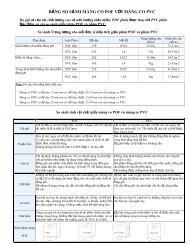
Brueninghaus Hydromatik<br />
<strong>Variable</strong> <strong>Pump</strong> <strong>A2VK</strong> <strong>series</strong> 1 <strong>and</strong> 4<br />
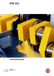
Model for <strong>Pump</strong>ing Plastics Components<br />
Axial Piston, Bent Axis Design<br />
NG 12 ... 107 Nominal Pressure 250 bar Peak Pressure 315 bar<br />
<strong>RE</strong> <strong>94000</strong>/05.95<br />
<strong>RE</strong><br />
<strong>94000</strong>/<strong>05.85</strong><br />
Replaces 06.79<br />
Axial Piston high pressure variable pumps are used for the pumping <strong>and</strong><br />
metering of polyurethane components..<br />
The particular advantages offered by the <strong>A2VK</strong> variable pumps are:<br />
● High metering accuracy <strong>and</strong> repeatability<br />
of the variable flows<br />
● Manual control via h<strong>and</strong>wheel with built-in-precision measuring<br />
scale or alternatively mechanical rod control, for mounting<br />
pneumatic or hydraulic control cylinders (remote control)<br />
● Operating pressure up to 250 bar<br />
● Low suction pressure, even when pumping highly viscous fluids<br />
● Very little pulsation of flow<br />
● Compatability of pump components with materials to be pumped<br />
(Polyol, Isocyanat) through use of specially matched materials <strong>and</strong><br />
special seals<br />
● Quiet operation<br />
● Optimum volumetric efficiency<br />
For certain applications:<br />
Constant capacity models available.<br />
Please consult our industrial transmissions sales dept.<br />
Brueninghaus Hydromatik 1/4
<strong>RE</strong> <strong>94000</strong>/<strong>05.85</strong><br />
<strong>Variable</strong> <strong>Pump</strong> <strong>A2VK</strong>, <strong>series</strong> 1 <strong>and</strong> 4<br />
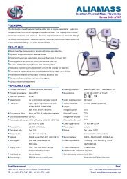
Ordering Code Short Code<br />
<strong>Pump</strong> Type<br />
<strong>Variable</strong> pump <strong>A2VK</strong><br />
Size<br />
11,6 cm≈ 12<br />
28,1 cm≈ 28<br />
54,8 cm≈ 55<br />
107,0 cm≈ 107<br />
(Displacement)<br />
Control Device<br />
Manual control MA<br />
Mechanical rod control GE<br />
Type of Circuit<br />
open circuit O<br />
closed circuit G<br />
Direction of Rotation (View on drive shaft)<br />
Clockwise R<br />
Anti-clockwise L<br />
Ordering Example:<br />
<strong>A2VK</strong>.55.MA.O.R.1.G.1.P.E.1<br />
<strong>Variable</strong> pump <strong>A2VK</strong>,<br />
size 55,<br />
with manual control MA,<br />
open circuits, clockwise rotation,<br />
<strong>series</strong> 1, design G, built-on<br />
pressure relief valve,<br />
parallel shaft with key, swivel<br />
to one side only,<br />
assembly design 1<br />
2/4 Brueninghaus Hydromatik<br />
<strong>A2VK</strong> 55 MA O R 1 G 1 P E 1<br />
Prior to finalising your design, please request certified installation drawing.<br />
All rights reserved.<br />
Assembly Design<br />
MA-h<strong>and</strong>wheel 1<br />
on left<br />
GE-mechanical rod<br />
on left<br />
MA-h<strong>and</strong>wheel 2<br />
on right<br />
GE-mechanical rod<br />
on right<br />
Viewed on drive shaft<br />
Swivel Movement<br />
to one side only E<br />
Shaft End<br />
Parallel, keyed P<br />
Valve Assembly<br />
without valve assembly 0<br />
built-on-pressure 1<br />
relief valve<br />
Design<br />
Housed pump G<br />
Series<br />
Size 28 - 107 1<br />
Size 12 4
<strong>Variable</strong> <strong>Pump</strong> <strong>A2VK</strong>, <strong>series</strong> 1 <strong>and</strong> 4<br />
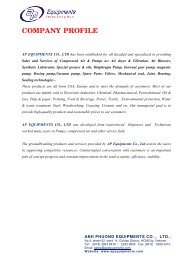
Technical Data<br />
Mounting Position: Optional; the unit must always be filled with<br />
oil.<br />
With MA control device: axis of h<strong>and</strong>wheel must be horizontal,<br />
because of position indicator.<br />
Direction of Flow<br />
Swivel Clockwise Rotation Anti- Rotation<br />
Direction Clockwise<br />
open circuit closed circuit open circuit closed circuit<br />
clockwise<br />
S to B<br />
A plugged<br />
A to B S to A<br />
B plugged<br />
B to A<br />
Anti- S to A B to A S to B A to B<br />
clockwise B plugged A plugged<br />
Table of Values<br />
Size<br />
Displacement Vg max<br />
Flow Qmax in open circuit <strong>and</strong> at speed<br />
(at a viscosity of ν = 36 mm2 /s)<br />
Power at Δp = 250 bar <strong>and</strong> speed<br />
MA Manual Control<br />
By turning the h<strong>and</strong>wheel, the pump swivel body <strong>and</strong> thus the<br />
displacement or output flow is infinitely varied within the range<br />
Q0 to Qmax via a self-locking threaded spindle.<br />
<strong>RE</strong> <strong>94000</strong>/<strong>05.85</strong><br />
Prior to finalising your design, please request certified installation drawing.<br />
All rights reserved.<br />
Operating Pressure Range - inlet side<br />
Open circuit:<br />
Prefill pressure 1 - 3 bar absolute at suction port S<br />
Closed circuit:<br />
Sum of combined pressures at A <strong>and</strong> B ≤ 250 bar ( 315 bar for<br />
short period), fit leakage line at port T.<br />
Operating Pressure Range - outlet side<br />
Pressure at port A or B<br />
Nominal pressure pN = 250 bar<br />
Peak pressure pmax = 315 bar<br />
(Pressure data to DIN 24312)<br />
12 28 55 107<br />
cm3 11,6 28,1 54,8 107<br />
n = 735 rpm l/min 8,3 20 39 76<br />
n = 970 rpm l/min 10,9 26 51 100<br />
n = 1450 rpm l/min 16,3 39 77 150<br />
n = 735 rpm kW 4 9 17 33<br />
n = 970 rpm kW 5 12 22 43<br />
n = 1450 rpm kW 7 17 33 65<br />
Curve Symbol<br />
Closed circuit<br />
Rotations of h<strong>and</strong>wheel Vg0 to Vg max Us 10,6 12,7 16 13,4<br />
Max. operating force on h<strong>and</strong>wheel kp 7 7 8 12<br />
Approx. weight (pump with control device) kg 19 36 64 117<br />
GE Mechanical Rod Control<br />
By means of the positioning rod, the pump swivel body <strong>and</strong> thus<br />
the displacement or output flow is infinitely varied within the<br />
range Q0 to Qmax .<br />
Control stroke s V g0 to V g max<br />
Operating force F (internal operating<br />
force of pump without accelerating force)<br />
at operating pressure<br />
Min. perm. control times t min V g0 to V g max<br />
Approx. weight (pump with control device)<br />
Curve Symbol<br />
Closed circuit<br />
mm 25,3 31,7 40,1<br />
p = 100 bar kp 23 35 56<br />
p = 150 bar kp 34,5 54 84<br />
p = 200 bar kp 46 73 112<br />
p = 250 bar kp 57,5 92 140<br />
s 0,03 0,004 0,005<br />
kg 30 57 105<br />
Brueninghaus Hydromatik 3/4
<strong>RE</strong> <strong>94000</strong>/<strong>05.85</strong><br />
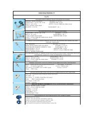
<strong>Variable</strong> <strong>Pump</strong> <strong>A2VK</strong>, <strong>series</strong> 1 <strong>and</strong> 4<br />
NG 12 NG 12 - 28<br />
2 shaft seals<br />
Inlet <strong>and</strong> outlet for<br />
sealing fluid<br />
M 8x1; 8 deep<br />
Keyed<br />
DIN 6885<br />
4/4 Brueninghaus Hydromatik<br />
B<br />
A<br />
R<br />
NG 55 - 107<br />
Bleed screw<br />
Drain<br />
NG 55 - 107<br />
S<br />
R<br />
Cover plate of filter<br />
not fitted when used<br />
in open circuit<br />
SAE connection<br />
flange<br />
Nominal pressure<br />
3000 psi<br />
Connections<br />
A, B service line<br />
B1 service line<br />
S suction line<br />
R air bleed<br />
T, T2 case drain<br />
Prior to finalising your design, please request certified installation drawing.<br />
All rights reserved.<br />
Swivel Movement<br />
Anti-clockwise Clockwise<br />
Control stroke<br />
Assembly Design 1 Assembly Design 2<br />
Built- on pressure relief valve<br />
A 19<br />
Size A A 1 A 2 A 3 A 4 A 5 A 6 A 7 A 8 A 9 A 10 A 11 A 12 A 13 A 14 A 15 A 16 A 17 A 18 thread depth A 20<br />
12 302 222 172 75 80 85 132 - 248 270 80 22,5 20 M 6 16 30 50 6 60 M 22x1,5 14 32<br />
28 357 257 195 95 90 106 142 - 286 308 100 27,9 25 M 8 16 38 62 8 73 M 27x2 16 40<br />
55 440 317 240 120 110 132,5 195 342,5 - - 125 32,9 30 M 12 28 49 74 10 88 M 33x2 18 50<br />
107 548 388 298 150 148 160 242 413,5 - - 160 43,1 40 M 12 28 66 94 12 110 M 42x2 20 63<br />
Size A21 A22 A23 thread depth A24 A25 B1 B2 B3 B4 B5 B6 B7 B8 thread depth B9 B10 D1 D2 thread depth E1 E2 12 58,7 30,2 M 10 15 1 1/4" 71 71 207 102 94 10 125 100 M 8 12 - - 32 M 6 9 22,5 -<br />
28 69,9 35,7 M 12 18 1 1/2" 80 85 218 110 102 10 125 125 M 10 15 104,5 162 40 M 8 11 27,5 28<br />
55 77,8 42,9 M 12 18 2" 125 120 272 125 115 12 200 160 M 16 24 119,6 180,4 48 M 10 12,5 33 33<br />
107 88,9 50,8 M 12 18 2 1/2" 160 150 303 150 132,5 22 200 200 M 16 24 44,5 222,5 60 M 12 15 40 40<br />
Size E3 E4 thread depth E5 E6 E7 thread depth E8 R1 Keyed<br />
DIN 6885 A/F Control stroke s Port T Port R<br />
12 - M 18x1,5 12 50 46 M 22x1,5 14 109,5 0,4 A 6x6x25,5 9 - M 12x1,5 M 27x1,5<br />
28 1 M 22x1,5 14 62 50 M 27x2 16 115,5 0,6 AS 8x7x32,5 9 25,3 M 16x1,5 M 27x1,5<br />
55 1,5 M 27x2 16 77 56 M 33x2 18 133,5 1,6 AS 8x7x43 10 31,7 M 18x1,5 M 27x1,5<br />
107 1,5 M 33x2 18 90 65 M 42x2 20 166 1,6 AS 12x8x57 19 40,1 M 18x1,5 M 42x1,5<br />
Brueninghaus Hydromatik GmbH, Plant Elchingen, Glockeraustraße 2, D–89275 Elchingen 2, Tel. (07308) 820, Telex 712538, Fax (07308) 7274<br />
T<br />
T 1<br />
T<br />
B 1<br />
GE<br />
MA