Design and Development of a Diagnostics Client for a Beam Loss ...
Design and Development of a Diagnostics Client for a Beam Loss ...
Design and Development of a Diagnostics Client for a Beam Loss ...

You also want an ePaper? Increase the reach of your titles
YUMPU automatically turns print PDFs into web optimized ePapers that Google loves.
<strong>Design</strong> <strong>and</strong> <strong>Development</strong> <strong>of</strong> a <strong>Diagnostics</strong> <strong>Client</strong> <strong>for</strong> a <strong>Beam</strong> <strong>Loss</strong> Measurement System at CERN<br />
provided to configure <strong>and</strong> customize all chart elements (e.g. colors, fonts, data ranges…)<br />
programmatically. The package has a nice user interface <strong>and</strong> also the ability to develop its<br />
functionality in general. Last but not least, the package <strong>of</strong>fers class-leading per<strong>for</strong>mance,<br />
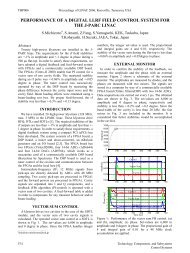
a very important feature <strong>for</strong> our data-intensive application. A visual example <strong>of</strong> a Chart<br />
component <strong>and</strong> different renderers <strong>and</strong> scales, produced by the JDVE package is shown<br />
in Figure 13.<br />
Figure 13: Chart component with three rendering types associated with three different Y scales.<br />
[13]<br />
4.4.2 Online Acquisition Data Display<br />
The most important tab <strong>and</strong> starting point <strong>of</strong> the diagnostics GUI client application is the<br />
online display. Data transmitted by the embedded server <strong>and</strong> received by the client are<br />
plotted on the online display after the desired data reduction. The online acquisition user<br />
interface is shown in Figure 14.<br />
The online user interface is the first <strong>and</strong> default tab, which a user who starts the diagnostics<br />
client observes. A number <strong>of</strong> different settings have to be set be<strong>for</strong>e starting an online<br />
session.<br />
First <strong>of</strong> all, a user has to select the data type <strong>of</strong> the acquisition, i.e. single or multi-channel<br />
processed data. This setting is represented by a group <strong>of</strong> two radio buttons <strong>and</strong> is lo-<br />
cated in the north-west <strong>of</strong> the GUI. It is referring to the 3 different modes <strong>of</strong> acquisition<br />
<strong>of</strong> the BLEDP cards. The next important setting is referring to the channel selection <strong>and</strong><br />
is represented also by a group <strong>of</strong> 8 radio buttons. This setting has to be set only when<br />
we have single-channel transmission. Hereupon, the next group <strong>of</strong> settings refers to the<br />
connection with the BLEDP server. It is a group <strong>of</strong> 3 text fields, in which the user must<br />
enter in<strong>for</strong>mation about the remote address <strong>of</strong> the embedded server <strong>and</strong> the TCP remote<br />
port. The third field is the UDP port <strong>and</strong> is referring to the local port, where acquisition<br />
data are coming, when the UDP protocol is engaged <strong>for</strong> the data transmission. To be<br />
noted here, that if the application is running on a PC, this port number has to be opened<br />
<strong>and</strong> secured in order to receive data, because in many cases, an installed firewall blocks<br />
Emmanouil I. Angelogiannopoulos 31