Design and Development of a Diagnostics Client for a Beam Loss ...
Design and Development of a Diagnostics Client for a Beam Loss ...
Design and Development of a Diagnostics Client for a Beam Loss ...

You also want an ePaper? Increase the reach of your titles
YUMPU automatically turns print PDFs into web optimized ePapers that Google loves.
<strong>Design</strong> <strong>and</strong> <strong>Development</strong> <strong>of</strong> a <strong>Diagnostics</strong> <strong>Client</strong> <strong>for</strong> a <strong>Beam</strong> <strong>Loss</strong> Measurement System at CERN<br />
verter is attached to the differential output <strong>of</strong> the integrator.<br />
• Direct Analogue Digital Conversion (DADC) circuit. In this method the ADC converter<br />
is attached to the input resistor on which the voltage drop is measured.<br />
In this way the measurement range is split into two overlapping ranges. The FDFC is<br />
used between 10 pA – 30 mA <strong>and</strong> the DADC between 100μΑ – 200 mA. The analogue<br />
switch, that selects which <strong>of</strong> the two circuits is active at any given time, is automatic <strong>and</strong><br />
controlled by the FPGA device. A module inside the FPGA is monitoring the data stream<br />
<strong>and</strong> depending on the measurements it receives, selects the most suitable measurement<br />
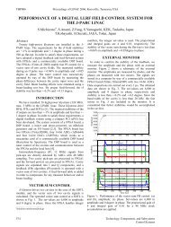
method <strong>for</strong> the next period. This switching between the two principles, depending on the<br />
input current, can be seen in Figure 5.<br />
Figure 5: FDFC <strong>and</strong> DADC switch<br />
The FDFC method is using an integrator <strong>and</strong> a status signal to select in which branch <strong>of</strong><br />
the fully differential stage, the input current is integrated. This mechanism is shown in<br />
Figure 6.<br />
The FDFC circuit’s output is processed by the FPGA device. The outputs <strong>of</strong> both ana-<br />
logue comparators are complemented by the ADC samples to reach higher measurement<br />
precision. The calculation <strong>of</strong> the integrated loss is triggered by the FPGA over a 2 μs<br />
period. [18] This also marks the integration period, in which the measurement result is<br />
produced. In general, most <strong>of</strong> the operations are h<strong>and</strong>led by the FPGA. So, the FPGA<br />
defines when the acquisition period starts or stops. It also keeps a count <strong>of</strong> the pulses<br />
occurred in the acquisition period <strong>and</strong> clocks the ADC circuitries in order to make differ-<br />
ences <strong>of</strong> the recorded ADC values. Finally, it processes the data <strong>and</strong> provides this 2μs<br />
integral per acquisition channel.<br />
Emmanouil I. Angelogiannopoulos 20