Design and Development of a Diagnostics Client for a Beam Loss ...
Design and Development of a Diagnostics Client for a Beam Loss ...
Design and Development of a Diagnostics Client for a Beam Loss ...

Create successful ePaper yourself
Turn your PDF publications into a flip-book with our unique Google optimized e-Paper software.
<strong>Design</strong> <strong>and</strong> <strong>Development</strong> <strong>of</strong> a <strong>Diagnostics</strong> <strong>Client</strong> <strong>for</strong> a <strong>Beam</strong> <strong>Loss</strong> Measurement System at CERN<br />
range <strong>and</strong> maximum linear response <strong>of</strong> each channel <strong>and</strong> check frequently the complete<br />
channel’s connection. [19]<br />
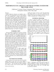
In Figure 3 below, the Acquisition Crate <strong>and</strong> some <strong>of</strong> its Technical elements are shown.<br />
Figure 3: Acquisition Crate’s Elements<br />
The detailed description <strong>of</strong> the elements is not part <strong>of</strong> this thesis. Complete in<strong>for</strong>mation<br />
about these technical elements <strong>of</strong> the <strong>Beam</strong> <strong>Loss</strong> Electronic Acquisition Crate can be<br />
found in the corresponding notes. [14]<br />
3.2.2 <strong>Beam</strong> <strong>Loss</strong> Electronic Dual Polarity (BLEDP)<br />
The BLEDP is the <strong>Beam</strong> <strong>Loss</strong> Electronic Dual Polarity Card. It is the most important part <strong>of</strong><br />
the BLEAC <strong>and</strong> its aim is to measure with high precision the current produced by the <strong>Beam</strong><br />
<strong>Loss</strong> Monitors. The crate can host up to 8 BLEDP cards. The BLEDP card contains an<br />
Altera Cyclone IV GX FPGA in which a Nios II s<strong>of</strong>t processor is implemented. The server<br />
application implemented in this processor is written in C. Each card can acquire up to 8<br />
input channels, so the total <strong>of</strong> input channels available on the crate can sum up to 64 (8x8).<br />
In addition, each card has an Ethernet Link, in order to be able to connect with the network<br />
<strong>for</strong> external diagnosis. The diagnostics client communicates with the cards through this<br />
link. The card implements two types <strong>of</strong> measurement: (i) The Fully Differential Frequency<br />
Converter (FDFC) <strong>and</strong> (ii) The Direct Acquisition Data Converter (DADC). Both methods<br />
produce raw digitized input at different rates:<br />
• In the FDFC mode, the input current is integrated during 2μs period. The integrator<br />
produce count pulses which are combined with ADC values to provide precise digital<br />
values at 0.5 MSPS rate (i.e. one sample every 2μs).<br />
• In the DADC mode the input current is converted into ADC values with the same<br />
conversion frequency <strong>of</strong> 0.5 MSPS (i.e. one sample every 2 μs).<br />
Emmanouil I. Angelogiannopoulos 18