Montageanleitung Assembly instructions ... - Villeroy & Boch
Montageanleitung Assembly instructions ... - Villeroy & Boch
Montageanleitung Assembly instructions ... - Villeroy & Boch

You also want an ePaper? Increase the reach of your titles
YUMPU automatically turns print PDFs into web optimized ePapers that Google loves.
SX-line<br />
3. <strong>Assembly</strong><br />
3.12. Stove safety grille<br />
Corner assembly<br />
5000149/10.05<br />
Note that the indicated minimum clearances must be maintained.<br />
. For details of minimum clearances, see stove assembly <strong>instructions</strong> and/or plate<br />
fixed to stove.<br />
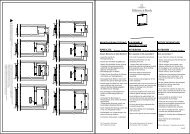
The stove safety grille consists of (fig. 25):<br />
d a front section<br />
d a side section<br />
d a base section<br />
d acover<br />
d Four screws (3 x 25)<br />
d Four screws (5 x 70)<br />
d Four plugs (12 x 40).<br />
1. Align the side and front section in an upright<br />
position with the plug hole before fitting.<br />
2. Screw the side and front section to the base<br />
using four screws (5 x 70) and four plugs<br />
(12 x 40) (fig. 25).<br />
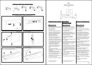
3. Attach the cover to the stove safety grille with<br />
wooden plugs (6 x 30, supplied) and glue.<br />
Cover<br />
4. Mark the four fixing positions in accordance with<br />
the specified clearances as per OK FFB 450.5 mm<br />
+ 805.5 mm and at a distance of 448 mm + 582<br />
mm on the wall element.<br />
5. Make four fixing holes with a ø 2 mm drill at the<br />
specified points.<br />
6. Insert four screws (3 x 25) into the wall elements<br />
(fig. 25 + 25.1). 448<br />
7. Fit the stove safety grille to the four screws in the<br />
wall elements (fig. 26).<br />
Screw 5 x 70<br />
Screw 3 x 25<br />
450,5<br />
805,5<br />
OK FFB<br />
Top plug holes<br />
582<br />
Stove<br />
Stove<br />
Plug 12 x 40<br />
Fig. 25<br />
Fig. 25.1<br />
Fig. 26<br />
K0026_1<br />
PAGE 45