Montageanleitung Assembly instructions ... - Villeroy & Boch
Montageanleitung Assembly instructions ... - Villeroy & Boch
Montageanleitung Assembly instructions ... - Villeroy & Boch

You also want an ePaper? Increase the reach of your titles
YUMPU automatically turns print PDFs into web optimized ePapers that Google loves.
SX-line<br />
3. <strong>Assembly</strong><br />
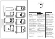
3.6. Ceiling elements<br />
1. Check the angles of the cabin and correct as<br />
required.<br />
2. Fit the first ceiling element.<br />
. The tongues on the ceiling element must engage<br />
fully with the groove in the wall section (fig. 14).<br />
. Joining of the individual ceiling elements is<br />
carried out in the same was as for the wall<br />
elements (but without fixing nails).<br />
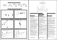
3. If the ceiling elements can be screwed into place<br />
from above, screw the ceiling post down on the<br />
wall element (6 x 100).<br />
4. Pre-drill the moulding strip with Ø 5 mm holes<br />
(with first hole 150 mm from the corner and<br />
further holes at intervals of 400 - 500 mm along<br />
the centre of the board).<br />
5. Screw the moulding strip to the wall element at a<br />
distance of 2 mm from the ceiling (5 x 70 mm)<br />
(fig. 18).<br />
. A clearance of 2mm must be maintained<br />
between the ceiling and the moulding strip.<br />
6. Pre-drill the moulding strip with Ø 5 mm holes,<br />
with an offset of approx. 10-20 mm with respect<br />
to the wall screws, and screw to the ceiling<br />
element (5 x 70).<br />
. Tighten the screws to pull the ceiling elements<br />
down onto the wall elements.<br />
5000149/10.05<br />
2<br />
Moulding strip<br />
Fig. 14<br />
K0374<br />
PAGE 39