Montageanleitung Assembly instructions ... - Villeroy & Boch
Montageanleitung Assembly instructions ... - Villeroy & Boch
Montageanleitung Assembly instructions ... - Villeroy & Boch

You also want an ePaper? Increase the reach of your titles
YUMPU automatically turns print PDFs into web optimized ePapers that Google loves.
SX-line<br />
3. <strong>Assembly</strong><br />
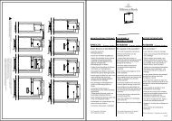
3.2. Wall elements<br />
1. Before assembling the next wall element, push<br />
the frame tongue and element tongues into the<br />
upright wall element.<br />
. The rounded edge is visible from the outside.<br />
2. Secure the frame tongue with three nails<br />
(20 x 40).<br />
3. Push the tongue into the groove in the plank.<br />
4. Add some spots of adhesive to the tongue, if<br />
necessary, to prevent slippage.<br />
. The tongues must lie flush with the wall element<br />
at the top to allow the ceiling elements to be<br />
pushed into place.<br />
. Stick the compressed sealing strip to the frame<br />
between the frame and tongue.<br />
5. Set up the next wall element on the floor frame.<br />
6. Push the wall elements fully together and secure<br />
with fixing nails (fig. 7).<br />
7. Assemble the remaining wall elements in the<br />
same way.<br />
. The last element to be fitted must be easily<br />
accessible from outside.<br />
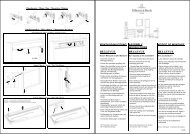
3.3. Wall ventilation element<br />
. Fit the wall ventilation element opposite or in a<br />
diagonal position to the sauna stove.<br />
. Refer to the layout plan for exact details of<br />
location.<br />
1. The ready-cut ventilation opening must lie at the<br />
bottom of the cabin’s inner wall (fig. 8).<br />
2. The ventilation opening on the outside of the<br />
cabin should be cut before assembling.<br />
5000149/10.05<br />
inside<br />
inside<br />
Frame tongue<br />
Nail 16 x 30<br />
Fixing nail<br />
Nail 20 x 40<br />
Sealing strip<br />
Tongue<br />
Fig. 6<br />
K0162<br />
Fig. 7<br />
K0110<br />
Fig. 8<br />
K0111_1<br />
PAGE 35