Montageanleitung Assembly instructions ... - Villeroy & Boch
Montageanleitung Assembly instructions ... - Villeroy & Boch
Montageanleitung Assembly instructions ... - Villeroy & Boch

You also want an ePaper? Increase the reach of your titles
YUMPU automatically turns print PDFs into web optimized ePapers that Google loves.
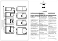
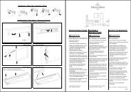
3. <strong>Assembly</strong><br />
3.2. Wall elements<br />
. Start by assembling the wall elements that are<br />
most difficult to access.<br />
. The vapour barrier is located on the inside of the<br />
cabin.<br />
Corner assembly<br />
. If there is sufficient space outside the cabin, it is<br />
preferable to screw the wall elements to the floor<br />
frame first.<br />
1. Align the corner post at the top to ensure that it<br />
lies flush with the wall element (fig. 4). Screw the<br />
wall elements to the pre-drilled corner post<br />
(6 x 70).<br />
. Position the light in accordance with the layout<br />
plan.<br />
2. Drill the hole for the light (∅ 10 mm, 245 mm<br />
from ceiling) through the corner post.<br />
3. Pull in the connection lead for the light.<br />
4. Locate the pre-fitted wall elements on the floor<br />
frame with the frame tongue facing downwards.<br />
. The frame tongues must engage snugly with the<br />
groove in the floor frame.<br />
Wall element<br />
Vapour barrier<br />
Pre-fitted<br />
Frame tongue<br />
Floor frame<br />
Corner post<br />
SX-line<br />
Outside Inside<br />
Fig. 3<br />
K0349_1<br />
Wall elements<br />
Fig. 4<br />
K0107<br />
Fig. 5<br />
K0108<br />
PAGE 34 5000149/10.05