Montageanleitung Assembly instructions ... - Villeroy & Boch
Montageanleitung Assembly instructions ... - Villeroy & Boch
Montageanleitung Assembly instructions ... - Villeroy & Boch

Create successful ePaper yourself
Turn your PDF publications into a flip-book with our unique Google optimized e-Paper software.
SX-line<br />
3. <strong>Assembly</strong><br />
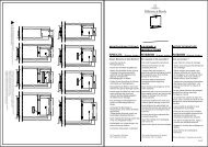
3.1. Floor frame<br />
Rectangular cabin:<br />
5000149/10.05<br />
Note that the floor frame must be horizontally aligned.<br />
Prepare frame.<br />
1. Align floor frame horizontally.<br />
2. Adapt floor frame to correct any incline (up to<br />
30 mm possible).<br />
3. With greater inclines, insert shims to level up the<br />
floor frame.<br />
4. Reinforce the corners of the floor frame by<br />
screwing on metal angle pieces (3.5 x 25) (fig. 1).<br />
. If the alignment of the floor frame has to be<br />
corrected by more than 10 mm, the lower metal<br />
angle piece is not used in these areas.<br />
. The ventilation opening in the floor frame is<br />
located near the stove.<br />
. The floor frame must now be precisely located in<br />
the place where the sauna is to be set up.<br />
Minimum clearance with respect to existing wall<br />
60 mm).<br />
. Attempts to displace the sauna after it is<br />
assembled are extremely difficult and likely to<br />
damage the frame.<br />
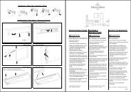
Five-cornered cabin:<br />
. Carry out assembly as described in <strong>instructions</strong><br />
for rectangular cabin.<br />
1. Reinforce the 90° corners with screw-on metal<br />
angle pieces (3.5 x 25).<br />
2. Reinforce the 135° corners with movable<br />
screw-on metal angle pieces (3.5 x 25) (Fig. 2).<br />
Angle 90°<br />
Air inlet<br />
Angle 90°<br />
Four screws 3.5 x 25<br />
Angle 135°<br />
Four screws 3.5 x 25<br />
Detail Z<br />
Z<br />
Fig. 1<br />
K0104<br />
Detail Z<br />
Z<br />
Fig. 2<br />
K0105<br />
PAGE 33