Montageanleitung Assembly instructions ... - Villeroy & Boch
Montageanleitung Assembly instructions ... - Villeroy & Boch
Montageanleitung Assembly instructions ... - Villeroy & Boch

You also want an ePaper? Increase the reach of your titles
YUMPU automatically turns print PDFs into web optimized ePapers that Google loves.
2. <strong>Assembly</strong> <strong>instructions</strong><br />
SX-line<br />
Electrical power supply<br />
d Sauna units must be hard-wired into the mains electrical system in accordance with the<br />
specifications of the Association of German Electrical Engineers (VDE) or your local equivalent. Fit<br />
aInN ≤ 0,03 A fault-current circuit breaker with a minimum contact opening of 3 mm to the<br />
power supply line.<br />
d Run the lead over the centre of the front wall of the sauna before starting installation work on the<br />
ceiling of the room. The lead must reach the floor with about one metre of cable to spare.<br />
d Refer to the control unit installation <strong>instructions</strong> for details of the electrical connections.<br />
DANGER WARNING<br />
Not that the control system must be connected to the mains supply by a service<br />
engineer or locally-authorized electrician.<br />
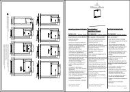
Configuration of cabin interior<br />
The SX line sauna is designed to allow various different configurations of the cabin interior with respect<br />
to the layout of the door, the electrical wall element and ventilation element.<br />
Location of sauna stove and positioning of wall ventilation element<br />
Install the sauna stove on the inside of the electrical wall element. Fit the wall ventilation element<br />
opposite or in a diagonal position to the electrical wall element. It is easier to install to the side wall that<br />
is visible from outside.<br />
A glass wall element is normally fitted next to the door.<br />
. For details of the layout of the individual wall elements, please refer to the illustrations in chapter 1<br />
”Configuration variants” and the layout plan provided.<br />
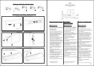
The wall elements for the inward-facing walls (two sides) are covered with planking made of<br />
wood-based material, while the two visible wall sides are covered with profile sections.<br />
The following assembly <strong>instructions</strong> describe the order of the assembly tasks.<br />
PAGE 32 5000149/10.05