Montageanleitung Assembly instructions ... - Villeroy & Boch
Montageanleitung Assembly instructions ... - Villeroy & Boch
Montageanleitung Assembly instructions ... - Villeroy & Boch

Create successful ePaper yourself
Turn your PDF publications into a flip-book with our unique Google optimized e-Paper software.
SX-line<br />
Notes and key to symbols used in these <strong>instructions</strong><br />
5000149/10.05<br />
Note!<br />
D required to act<br />
d for enumerations<br />
Safety precautions<br />
. additional <strong>instructions</strong><br />
Number entries in drawings and text:<br />
Dimensions in drawings are given in mm.<br />
Number entries in the text that appear in brackets are sizes of screws or nails, e.g. (4 x 32), required for<br />
assembly of the section in question. The example refers to a 4 mm diameter screw with a length of<br />
32 mm.<br />
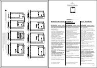
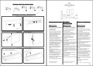
2. <strong>Assembly</strong> <strong>instructions</strong><br />
Carefully read through the assembly <strong>instructions</strong> BEFORE starting work!<br />
Floor<br />
The floor, which must be perfectly level, should consist of cement screed, clinker or tiles.<br />
The floor should be easy to clean.<br />
DANGER WARNING<br />
If the floor is made of a flammable material such as wood or plastic, place a sheet of<br />
non-flammable material (e.g. Promatect) under the sauna stove.<br />
The size of the sheet should be in accordance with that of the stove safety grille.<br />
Avoiding condensation<br />
If the ceiling is ”cold” (e.g. due to a flat roof or unheated garage), condensation may form above the<br />
cabin. To avoid this, cold walls and water conduits in the immediate vicinity of the sauna should be<br />
heat-insulated with a vapour barrier material (heat insulation is not included with the shipment).<br />
Ensure that there is sufficient air circulation at the place of installation.<br />
Maintain the minimum clearances: 100 mm between the cabin roof and the room ceiling and 40 mm<br />
between the outer wall and cabin wall.<br />
PAGE 31