Montageanleitung Assembly instructions ... - Villeroy & Boch
Montageanleitung Assembly instructions ... - Villeroy & Boch
Montageanleitung Assembly instructions ... - Villeroy & Boch

You also want an ePaper? Increase the reach of your titles
YUMPU automatically turns print PDFs into web optimized ePapers that Google loves.
<strong>Montageanleitung</strong><br />
SX-line ........................................................................ 3<br />
<strong>Assembly</strong> <strong>instructions</strong><br />
SX line ........................................................................ 27<br />
Instructions de montage<br />
Ligne SX ....................................................................... 51<br />
Montagehandleiding<br />
SX-line ........................................................................<br />
75
SEITE 2<br />
SANARIUM
<strong>Montageanleitung</strong><br />
SX-line
Inhaltsverzeichnis Seite<br />
1. Aufbauvarianten (Standard) ......................................... 5<br />
2. Montagehinweise .................................................. 7<br />
3. Montage ......................................................... 9<br />
3.1. Bodenrahmen ............................................................ 9<br />
3.2. Wandelemente ........................................................... 10<br />
3.3. Abluft-Wandelement ...................................................... 11<br />
3.4. Kabinenvorderwand mit Tür ................................................. 13<br />
3.5. Montage der Saunatüre bei 5-Eck Kabine ...................................... 14<br />
3.6. Deckenelemente .......................................................... 15<br />
3.7. Türe befestigen ........................................................... 16<br />
3.8. Saunaliegen .............................................................. 16<br />
3.9. Saunainstrumente ......................................................... 18<br />
3.10. Saunaleuchte ............................................................. 19<br />
3.11. Saunaofen ............................................................... 20<br />
3.12. Ofenschutzgitter .......................................................... 21<br />
3.13. Außen-Abschlussarbeiten .................................................. 23<br />
4. Pflege ............................................................ 25<br />
Allgemeine Hinweise ...................................................... 25<br />
5. Gewährleistung .................................................... 25<br />
6. Informatie Information ............................................<br />
26
SX-line<br />
1. Aufbauvarianten (Standard)<br />
Rechteck Varianten<br />
. Alle rechteckigen Aufbauvarianten sind auch spiegelbildlich erhältlich.<br />
5000149/10.05<br />
SEITE 5
1. Aufbauvarianten (Standard)<br />
5-Eck Varianten<br />
SX-line<br />
SEITE 6 5000149/10.05
SX-line<br />
Hinweis und verwendete Symbole in dieser Anleitung<br />
5000149/10.05<br />
Hinweis!<br />
D fordert zum Handeln auf<br />
d bei Aufzählungen<br />
Sicherheitshinweis<br />
. zusätzliche Hinweise<br />
Zahlenangaben in Zeichnungen und im Text:<br />
Maße in Zeichnungen beziehen sich auf die Einheit mm.<br />
Bei Zahlenangaben im Text, die in Klammer gefasst sind, handelt es sich um die Größe der für diesen<br />
Montageabschnitt benötigten Schrauben oder Nägel, z. B. (4 x 32) entspricht einer Schraube mit 4 mm<br />
Durchmesser und 32 mm Länge.<br />
2. Montagehinweise<br />
Lesen Sie die Montagehinweise aufmerksam durch, bevor Sie mit der Montage<br />
beginnen!<br />
Fußboden<br />
Der Fußboden muss aus Zement-Estrich, Klinker oder Fliesen bestehen und waagerecht sein.<br />
Der Boden soll leicht zu reinigen sein.<br />
Gefahr!<br />
Bei Fußböden aus brennbaren Materialien wie z. B. Holz oder Kunststoff, unter den<br />
Saunaofen eine Platte aus nicht brennbarem Material anbringen, z. B. aus Promatect.<br />
Die Größe der Platte richtet sich nach dem Ofenschutzgitter.<br />
Vermeiden von Schwitzwasser<br />
Durch kalte Decken (z. B. durch eine Terrasse oder eine ungeheizte Garage) kann sich Schwitzwasser<br />
über der Saunakabine bilden. Um das zu vermeiden, an kalten Wänden und Wasserleitungen, die sich in<br />
unmittelbarer Nähe der Sauna befinden, eine Wärmedämmung mit Dampfsperre anbringen (die<br />
Wärmedämmung ist nicht im Lieferumfang enthalten).<br />
Für eine ausreichende Luftzirkulation am Aufstellort sorgen.<br />
Mindestabstände einhalten: 100 mm zwischen Kabinendecke und Raumdecke und 40 mm zwischen<br />
Außenwand und Kabinenwand.<br />
SEITE 7
2. Montagehinweise<br />
Elektrische Zuleitung<br />
d Die Saunaanlagen nur nach den VDE-Vorschriften durch einen festen Anschluss mit dem Netz<br />
verbinden. In der Anschlusszuleitung einen Fehlerstromschalter InN ≤ 0,03 A mit mindestens<br />
3 mm Kontaktöffnung verwenden.<br />
d Die Zuleitung vor Montagebeginn an der Raumdecke bis über die Mitte der Saunavorderwand<br />
verlegen. Die Leitung muss bis auf den Fußboden reichen plus ca. 1 m länger sein.<br />
d Den elektrischen Anschluss der Saunasteuerung aus der <strong>Montageanleitung</strong> der Steuerung<br />
entnehmen.<br />
SX-line<br />
Gefahr!<br />
Die Steuerung nur durch einen Service-Monteur oder durch einem örtlich zugelassenen<br />
Elektrofachmann an das Stromnetz anschließen lassen!<br />
Kabinen-Aufteilung innen<br />
Die Sauna SX-line ist so konstruiert, dass verschiedene Möglichkeiten der Kabinen-Innenaufteilung, die<br />
Anordnung der Tür, des Elektro-Wandelementes und des Abluft-Elementes gegeben sind.<br />
Aufstellort Saunaofen und Position Abluftwandelement<br />
Den Saunaofen auf der Innenseite des Elektrowandelementes montieren. Das Abluftwandelement<br />
gegenüber oder diagonal zum Elektrowandelement montieren. Günstig ist die Montage an der von<br />
außen sichtbaren Seitenwand.<br />
Ein Glaswandelement wird in der Regel neben der Tür eingesetzt.<br />
. Die Anordnung der einzelnen Wandelemente den Abbildungen in Kapitel 1 Aufbauvarianten,<br />
sowie dem beigepackten Liegenplan entnehmen.<br />
Die Wandelemente für die bauseitigen Wände (zwei Seiten) sind mit einer Holzwerkstoffplatte<br />
beplankt, die zwei sichtbaren Wandseiten sind mit Profilbrettern beplankt.<br />
Die folgende <strong>Montageanleitung</strong> beschreibt die Reihenfolge der Montageschritte.<br />
SEITE 8 5000149/10.05
SX-line<br />
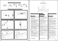
3. Montage<br />
3.1. Bodenrahmen<br />
Rechteck-Kabine:<br />
5000149/10.05<br />
Den Bodenrahmen waagerecht ausrichten!<br />
Rahmen vorbereiten.<br />
1. Bodenrahmen waagerecht ausrichten.<br />
2. Bei Gefälle den Bodenrahmen anpassen (bis<br />
30 mm möglich).<br />
3. Bei größerem Gefälle Bodenrahmen unterlegen.<br />
4. Ecken des Bodenrahmens mit Metallwinkeln<br />
verschrauben (3,5 x 25) (Abb. 1).<br />
. Muss der Bodenrahmen mehr als 10 mm<br />
nachgearbeitet werden, entfällt in diesem Bereich<br />
der untere Metallwinkel.<br />
. Die Zuluftöffnung im Bodenrahmen befindet sich<br />
in der Nähe des Ofens.<br />
. Der Bodenrahmen muss nun exakt an der Stelle<br />
liegen, auf der später die Sauna stehen soll.<br />
Abstand zur bauseitigen Wand mind. 60 mm.<br />
. Ein Verschieben der aufgebauten Sauna ist nur<br />
schwer möglich und beschädigt ggf. den<br />
Rahmen.<br />
5-Eck Kabine:<br />
. Montage wie bei Rechteck-Kabine beschrieben<br />
durchführen.<br />
1. Die 90°-Ecken mit den Metallwinkeln<br />
verschrauben (3,5 x 25).<br />
2. Die 135°-Ecken mit den beweglichen<br />
Metallwinkeln verschrauben (3,5 x 25) (Abb. 2).<br />
Winkel 90°<br />
Zuluft<br />
Winkel 90°<br />
vier Schrauben 3,5 x 25<br />
Winkel 135°<br />
vier Schrauben 3,5 x 25<br />
Detail Z<br />
Z<br />
Abb. 1<br />
K0104<br />
Detail Z<br />
Z<br />
Abb. 2<br />
K0105<br />
SEITE 9
3. Montage<br />
3.2. Wandelemente<br />
. Zuerst schwer zugängliche Wandelemente<br />
montieren.<br />
. Die Dampfsperre befindet sich auf der Innenseite<br />
der Kabine.<br />
Eckmontage<br />
. Bei ausreichendem Platz außerhalb der Kabine,<br />
die Wandelemente vorzugsweise auf dem<br />
Bodenrahmen verschrauben.<br />
1. Eckpfosten mit Wandelement oben bündig<br />
ausrichten (Abb. 4). Wandelemente mit dem<br />
vorgebohrten Eckpfosten verschrauben (6 x 70).<br />
. Die Position der Leuchte dem Liegenplan<br />
entnehmen.<br />
2. Die Bohrung für die Leuchte (∅ 10 mm, Abstand<br />
von der Decke 245 mm) durch den Eckpfosten<br />
bohren.<br />
3. Die Leitung für die Leuchte einziehen.<br />
4. Die vormontierten Wandelemente mit der<br />
Rahmenfeder nach unten auf den Bodenrahmen<br />
setzen.<br />
. DieRahmenfedernmüssenganzindieNutim<br />
Bodenrahmen einrasten.<br />
Wandelement<br />
Dampfsperre<br />
vormontierte<br />
Rahmenfeder<br />
Bodenrahmen<br />
Eckpfosten<br />
SX-line<br />
außen innen<br />
Abb. 3<br />
K0349_1<br />
Wandelemente<br />
Abb. 4<br />
K0107<br />
Abb. 5<br />
K0108<br />
SEITE 10 5000149/10.05
SX-line<br />
3. Montage<br />
3.2. Wandelemente<br />
1. Vor Montage des nächsten Wandelementes die<br />
Rahmenfeder und Elementfedern in das<br />
aufgesetzte Wandelement einschieben.<br />
. Die abgerundete Kante ist außen sichtbar.<br />
2. Die Rahmenfeder mit drei Nägeln (20 x 40)<br />
befestigen.<br />
3. Die Feder in die Brettnut einschieben.<br />
4. Die Feder evtl. punktleimen, um sie gegen<br />
Verrutschen zu sichern.<br />
. DieFedernmüssenobenmitdemWandelement<br />
bündig sein, um das Einrasten der<br />
Deckenelemente zu ermöglichen.<br />
. Zwischen Rahmen und Feder den komprimierten<br />
Dichtungsstreifen auf den Rahmen kleben.<br />
5. Das nächste Wandelement auf den Bodenrahmen<br />
stellen.<br />
6. Wandelemente ganz zusammenschieben und mit<br />
Wellennagel sichern (Abb. 7).<br />
5000149/10.05<br />
innen<br />
Rahmenfeder<br />
Nagel 16 x 30<br />
Nagel 20 x 40<br />
Dichtungsstreifen<br />
Feder<br />
Abb. 6<br />
K0162<br />
7. Restliche Wandelemente in gleicher Weise<br />
.<br />
montieren.<br />
Das zuletzt aufgestellte Element muss von außen<br />
gut zugänglich sein.<br />
innen<br />
Wellennagel<br />
Abb. 7<br />
K0110<br />
3.3. Abluft-Wandelement<br />
. Das Abluft-Wandelement gegenüber oder<br />
diagonal zum Saunaofen montieren.<br />
. Die genaue Lage dem Liegenplan entnehmen.<br />
1. Die werkseitig ausgeschnittene Abluftöffnung<br />
muss in der Kabineninnenseite unten sitzen<br />
(Abb. 8).<br />
2. Die Abluftöffnung auf der Kabinenaußenseite vor<br />
der Montage einschneiden.<br />
Abb. 8<br />
K0111_1<br />
SEITE 11
3. Montage<br />
3.3. Abluft-Wandelement<br />
Der Vorraum muss gut belüftet sein.<br />
Abluft direkt in den Vorraum leiten<br />
1. Die Unterkante der Abluftöffnung liegt<br />
ca. 1700 mm über dem fertigen Fußboden<br />
(Abb. 9).<br />
2. Die Abluftöffnung in der Mitte des<br />
Wandelements vorsehen. Die Abluftöffnung<br />
jedoch mittig verteilt über die Anzahl der<br />
betroffenen Bretter anbringen.<br />
3. Die Abluftöffnung (188 x 188) auf der<br />
Kabinenaußenseite einschneiden.<br />
4. Das Lamellengitter über die Abluftöffnung<br />
schrauben (3 x 25).<br />
Abluft über das Kabinendach in den Vorraum leiten<br />
1. Die Abluftöffnung in die Kabinenaußenseite des<br />
Abluft-Wandelementes einschneiden.<br />
2. Den mitgelieferten Anschluss-Stutzen auf den<br />
Ausschnitt schrauben (3,5 x 25) (Abb. 10).<br />
3. Die weitere Abluftführung kann z. B. mit einem<br />
150 mm PVC-Rohr erfolgen.<br />
4. Der Anschlussstutzen kann bei einem<br />
verlängerten Abluft-Wandelement auch über der<br />
Kabine angebracht werden.<br />
SX-line<br />
Abb. 9<br />
K0112<br />
SEITE 12 5000149/10.05<br />
1700<br />
Abb. 10<br />
K0212_1
SX-line<br />
3. Montage<br />
3.4. Kabinenvorderwand mit Tür<br />
Glastüre ohne Schwelle<br />
5000149/10.05<br />
Die Saunatür darf aus Sicherheitsgründen nur nach außen zu öffnen sein.<br />
1. Die Folie an der Kunststoffscheibe abziehen und<br />
mittig am Rahmen aufkleben (Abb. 12).<br />
2. Inneren und äußeren Türgriff mit den<br />
mitgelieferten Gewindestangen und den<br />
Kunststofftüllen montieren (Abb. 11.1).<br />
. Kunststofftüllen zwischen Glas und<br />
Gewindestange einlegen.<br />
. Die Türgriffe regelmäßig nachziehen.<br />
Abb. 12<br />
K0018_2<br />
Abb. 11.1<br />
K0018_4<br />
SEITE 13
3. Montage<br />
3.5. Montage der Saunatüre bei 5-Eck Kabine<br />
1. Alle Saunawände vorab montieren.<br />
2. 5-Eckpfosten auf den Türrahmen der Saunatüre<br />
aufschrauben (6 x 70) (Abb. 13).<br />
. Die Türseite der Pfosten ist aufgestempelt.<br />
3. Die 5-Eckfedern innen in die Pfosten einschieben und mit<br />
einem Nagel (16 x 30) gegen Verrutschen sichern.<br />
4. Den Türrahmen anheben und in die Aussparung einfügen.<br />
. Der Türrahmen rastet leichter ein, wenn ein Helfer die<br />
aufgestellten Wände oben leicht nach außen drückt.<br />
5. Den Türrahmen ganz nach unten schieben.<br />
. Der Türrahmen muss oben bündig mit den Wandelementen<br />
abschließen.<br />
6. Den Türrahmen am Eckpfosten links und rechts mit dem<br />
Wandteil verschrauben (6 x 70).<br />
7. 5-Eck-Deckbrett mit Feder in das Wandelement<br />
einschieben und mit Nagel (16 x 30) befestigen.<br />
. Wenn die Kabine komplett montiert ist, die Wandelemente<br />
links und rechts der Tür senkrecht nach dem Türblatt<br />
ausrichten.<br />
8. Die Türumrandungsleiste nach Abschluss der<br />
Außenverbretterung montieren.<br />
Wandelement<br />
5-Eckpfosten<br />
Türrahmen<br />
Glastür<br />
Türumrandungsleiste<br />
Spax 6 x 70<br />
5-Eck-Feder<br />
Wandelement<br />
Spax 6 x 70<br />
Lose Feder<br />
SX-line<br />
5-Eck-Deckbrett<br />
Abb. 13<br />
K0303<br />
SEITE 14 5000149/10.05
SX-line<br />
3. Montage<br />
3.6. Deckenelemente<br />
1. Winkel der Kabine prüfen, falls notwendig<br />
korrigieren.<br />
2. Erstes Deckenelement auflegen.<br />
. Die Federn des Deckenelementes in die Nut der<br />
Wandelemente einrasten (Abb. 14).<br />
. Die Verbindung der einzelnen Deckenelemente<br />
erfolgt ebenso wie die der Wandelemente (ohne<br />
Wellennagel).<br />
3. Ist eine Verschraubung der Deckenelemente von<br />
oben möglich, dann den Deckenpfosten mit dem<br />
Wandelement von oben verschrauben (6 x 100).<br />
4. Deckleiste mit Ø 5 mm vorbohren (erste Bohrung<br />
beginnt 150 mm von der Ecke, weitere<br />
Bohrungen im Abstand von 400 - 500 mm,<br />
jeweils Mitte Brett).<br />
5. Deckleiste an Wandelement mit 2 mm Abstand<br />
zur Decke anschrauben (5 x 70 mm) (Abb. 18).<br />
. Der Abstand zwischen Decke und Deckleiste<br />
muss 2 mm betragen.<br />
6. Deckleiste um ca. 10-20 mm versetzt zur<br />
Wandverschraubung mit Ø 5 mm vorbohren und<br />
an das Deckenelement anschrauben (5 x 70).<br />
. Durch das Anziehen der Schrauben werden die<br />
Deckenelemente auf die Wandelemente<br />
gezogen.<br />
5000149/10.05<br />
2<br />
Deckleiste<br />
Abb. 14<br />
K0374<br />
SEITE 15
3. Montage<br />
3.7. Türe befestigen<br />
1. Nachdem das letzte Wandelement aufgesetzt<br />
und befestigt ist, die Kabinentüre erneut auf<br />
Öffnen und Schließen kontrollieren.<br />
2. Den Türrahmen gleichmäßig verteilt je 4x links und<br />
rechts verschrauben.<br />
. Der Türstockrahmen wird bei Türen ohne<br />
Stockrahmen zusätzlich mit dem Bodenrahmen<br />
verschraubt (Spax 5 x 80 mit Kopflochbohrung<br />
für Kunststoffkappe) (Abb. 15).<br />
SX-line<br />
. Das Türblatt auf paralleles Anliegen an dem<br />
Türrahmen überprüfen und ggf. einstellen.<br />
3. Die Bodenfuge mit Silikon verfugen. Abb. 15<br />
3.8. Saunaliegen<br />
Montage der Saunaliegen<br />
1. Der Einbau der Liege erfolgt gemäß dem<br />
Liegenplan.<br />
2. In diesem Plan ist die Lage und die Höhe der<br />
Liege angegeben.<br />
3. Alle Auflageleisten vor dem Festschrauben in die<br />
Rahmenhölzer im Wandelement mit ∅ 5,5 mm<br />
vorbohren.<br />
d 25 mm links und rechts von jedem Wandstoß<br />
d Bei 600, 800 oder 1000 mm breiten<br />
Wandelementen jeweils in den beiden mittleren<br />
Brettern<br />
d Bei 500, 700 oder 900 mm breiten<br />
Wandelementen jeweils links und rechts vom<br />
mittleren Brett.<br />
4. Bei einem Glaselement im Bereich der<br />
Glasscheibe eine Abdeckblende an die<br />
Auflageleiste anschrauben (4,5 x 40) (Abb. 15).<br />
Abdeckblende<br />
. Die Schraube leicht versenken. Liege<br />
SEITE 16 5000149/10.05<br />
220<br />
904<br />
579<br />
4,5 x 40<br />
Abb. 16<br />
Abb. 17
SX-line<br />
3. Montage<br />
3.8. Saunaliegen<br />
Montage der durchlaufenden Liegen<br />
1. Die Falzleisten hochkant rechts und links an die<br />
Saunawand anschrauben (5 x 80).<br />
. An der Rückwand anstoßen lassen.<br />
2. Längs an den oberen Liegen rechts und links<br />
Holzklötze (28 x 22) als Abstandshalter<br />
anschrauben (4,5 x 50).<br />
Montage einer Winkelblockliege<br />
1. Eine ausgeklinkte Leiste an der durchlaufenden<br />
Liege anschrauben (5 x 80).<br />
. Die Winkelblockliege muss oben bündig sein.<br />
2. Eine ausgeklinkte Leiste an der<br />
gegenüberliegenden Wand anschrauben (5 x 80).<br />
Montage einer kurzen Winkelliege<br />
1. Eine Auflageleiste (34 x 54) an der<br />
durchlaufenden Liege anschrauben (5 x 80).<br />
. Die Winkelliege muss oben bündig sein.<br />
2. Eine Auflageleiste (34 x 54) an der<br />
gegenüberliegenden Wand anschrauben (5 x 80).<br />
5000149/10.05<br />
28<br />
22<br />
Liegefläche<br />
Abstandshalter<br />
37<br />
Abb. 18<br />
K0116<br />
50<br />
ausgeklinkte Leiste<br />
Abb. 19<br />
SEITE 17
3. Montage<br />
3.8. Saunaliegen<br />
Blende montieren<br />
1. Die Blende an der unteren durchlaufenden Liege<br />
von hinten anschrauben (6 x 100) (Abb. 20).<br />
Montage der Rückenlehne<br />
1. Die Rückenlehne an der Kabinenwand vermittelt<br />
vorsehen.<br />
2. Die Befestigungshöhe für die Ösen an der<br />
Rückenlehne 390 mm über der Liege vorsehen.<br />
3. Den Abstand zwischen den beiden Ösen an der<br />
Rückenlehne abmessen. Das gemessene Maß auf<br />
die Rückwand übertragen.<br />
4. Die Befestigungspunkte mit einem Bohrer 2,5 mm<br />
vorbohren. Die Spaxschrauben (4,5 x 25) in die<br />
Wandelemente schrauben.<br />
5. Die Rückenlehne einhängen.<br />
3.9. Saunainstrumente<br />
6 x 100<br />
Kein Instrument im Bereich des Ofenschutzgitters montieren.<br />
1. Thermometer oder Hygrometer an der<br />
Kabinenrückwand in der Saunakabine anbringen.<br />
. Die Instrumente sollen von außen durch die<br />
Saunatür zu sehen sein.<br />
2. Der Abstand von der Saunadecke bis zur Mitte<br />
der Instrumente soll 150 mm betragen.<br />
3. Die Sanduhr neben der Saunatür in einer Höhe<br />
von ca. 1200 mm über dem Fußboden<br />
anbringen.<br />
SX-line<br />
Abb. 20<br />
K0389<br />
Abb. 21<br />
SEITE 18 5000149/10.05
SX-line<br />
3. Montage<br />
3.10. Saunaleuchte<br />
5000149/10.05<br />
Die Saunaleuchte nicht über dem Saunaofen montieren.<br />
Die vorgegebenen Mindestabstände unbedingt einhalten.<br />
Zum Anschließen der Saunaleuchte muss die Steuerung vom Netz getrennt sein.<br />
1. Den Halter der Saunaleuchte in einer 90°-Ecke<br />
oben an der Deckleiste anschlagen und mit<br />
2 Schrauben (4 x 20) festschrauben.<br />
. Das Befestigungs- und Anschlussmaterial ist der<br />
Saunaleuchte beigepackt.<br />
2. Die Elektroleitung anschließen.<br />
3. Die Kabelabdeckung auf den Lampenhalter<br />
schrauben.<br />
4. Den Lampenschirm von unten auf den Halter der<br />
Saunaleuchte schieben.<br />
Abb. 22<br />
K0019_2<br />
Abb. 23<br />
K0019_3<br />
SEITE 19
3. Montage<br />
3.11. Saunaofen<br />
1. Den Saunaofen auf das Elektrowandelement<br />
montieren.<br />
. Zur Montage die angegebenen Mindestabstände<br />
in der <strong>Montageanleitung</strong> Ofen/am Ofenschild<br />
einhalten.<br />
. Die Schrauben und das Befestigungsmaterial ist<br />
dem Ofen beigepackt.<br />
2. Den Befestigungswinkel vom Saunaofen abziehen<br />
und an der Saunawand anschrauben.<br />
3. Die Einbaumaße der <strong>Montageanleitung</strong> des Ofens<br />
entnehmen.<br />
4. Den Saunaofen in den Befestigungswinkel<br />
einhängen (Abb. 24) und mit einer Schraube<br />
arretieren.<br />
5. Die Montage der Temperatursensoren ist in der<br />
<strong>Montageanleitung</strong> der Steuerung beschrieben.<br />
Innen-Ansicht<br />
Elektro-Wandteil<br />
Temperatur-Sensor + STB<br />
Wandofen<br />
SX-line<br />
Abb. 24<br />
K0118_1<br />
SEITE 20 5000149/10.05<br />
610<br />
100
SX-line<br />
3. Montage<br />
3.12. Ofenschutzgitter<br />
Eckmontage<br />
5000149/10.05<br />
Die vorgegebenen Mindestabstände einhalten!<br />
. Mindestabstände siehe <strong>Montageanleitung</strong> Ofen/am Ofenschild.<br />
Das Ofenschutzgitter besteht aus (Abb. 25):<br />
d Einem Frontteil<br />
d einem Seitenteil<br />
d einem Fuß<br />
d einer Abdeckung<br />
d vier Schrauben (3 x 25)<br />
d vier Schrauben (5 x 70)<br />
d vier Dübel (12 x 40).<br />
1. Das Seiten- und Frontteil zur Montage mit der<br />
Dübelbohrung nach oben ausrichten.<br />
2. Das Seiten- und Frontteil mit vier Schrauben<br />
(5 x 70) und vier Dübeln (12 x 40) mit dem Fuß<br />
verschrauben (Abb. 25).<br />
3. Die Abdeckung mit Holzdübeln (6 x 30<br />
beigepackt) und Leim auf das montierte<br />
Ofenschutzgitter montieren.<br />
4. Die vier Befestigungspositionen nach dem<br />
angegebenen Abstand zur OK FFB 450,5 mm +<br />
805,5 mm und in einem Abstand von 448 mm +<br />
582 mm am Wandelement anzeichnen.<br />
5. Die vier Befestigungspositionen mit einem Bohrer<br />
∅ 2 mm vorbohren.<br />
6. Vier Schrauben (3 x 25) in die Wandelemente<br />
schrauben (Abb. 25 + 25.1). 448<br />
7. Das Ofenschutzgitter an den vier Schrauben im<br />
Wandelemente einhängen (Abb. 26).<br />
Schraube 5 x 70<br />
Abdeckung<br />
Schraube 3 x 25<br />
450,5<br />
805,5<br />
OK FFB<br />
Dübelbohrungen oben<br />
582<br />
Ofen<br />
Ofen<br />
Dübel 12 x 40<br />
Abb. 25<br />
Abb. 25.1<br />
Abb. 26<br />
K0026_1<br />
SEITE 21
3. Montage<br />
3.12. Ofenschutzgitter<br />
Wandmontage<br />
Die vorgegebenen Mindestabstände einhalten!<br />
. Mindestabstände siehe <strong>Montageanleitung</strong> Ofen/am Ofenschild.<br />
Das Ofenschutzgitter besteht aus (Abb. 27):<br />
d Einem Frontteil<br />
d zwei Seitenteilen<br />
d zwei Füßen<br />
d einer Abdeckung<br />
d vier Schrauben (3 x 25)<br />
d acht Schrauben (5 x 70)<br />
d acht Dübel (12 x 40).<br />
1. Die zwei Seiten- und das Frontteil zur Montage<br />
mit der Dübelbohrung nach oben ausrichten.<br />
2. Die zwei Seiten- und das Frontteil mit<br />
acht Schrauben (5 x 70) und acht Dübeln<br />
(12 x 40) mit den zwei Füßen verschrauben.<br />
3. Die Abdeckung mit Holzdübeln (6 x 30<br />
beigepackt) und Leim auf das montierte<br />
Ofenschutzgitter montieren.<br />
4. Die vier Befestigungspositionen nach dem<br />
angegebenen Abstand zur OK FFB 450,5 mm +<br />
805,5 mm und in einem Abstand von 662 mm am<br />
Wandelement anzeichnen.<br />
5. Die vier Befestigungspositionen mit einem Bohrer<br />
∅ 2 mm vorbohren.<br />
6. Vier Schrauben (3 x 25) in die Wandelemente<br />
schrauben (Abb. 27 + 27.1).<br />
7. Das Ofenschutzgitter an die vier Schrauben im<br />
Wandelemente einhängen (Abb. 28).<br />
Abdeckung<br />
Schraube 5 x 70<br />
Schraube 3 x 25<br />
Dübel 12 x 40<br />
SX-line<br />
Abb. 27<br />
SEITE 22 5000149/10.05<br />
450,5<br />
805,5<br />
OK FFB<br />
Dübelbohrungen oben<br />
662<br />
Ofen<br />
Ofen<br />
Abb. 27.1<br />
Abb. 28
SX-line<br />
3. Montage<br />
3.13. Außen-Abschlussarbeiten<br />
. Die Außenverbretterung der Vorderwand und<br />
einer Seitenwand wird je nach Bestellung auf<br />
Raum- oder Kabinenhöhe ausgeführt.<br />
Bei raumhoher Verbretterung<br />
1. Die Aufdoppelleiste lose mitlaufen lassen.<br />
2. Die Außenverbretterung mit einem Abstand von<br />
ca. 8 mm zur Raumdecke anbringen.<br />
Beginn der Außenverbretterung<br />
1. Das Doppelnutbrett mit einem Abstand von<br />
5 mm zum senkrechten Rahmenholz des<br />
Türrahmens festschrauben.<br />
2. Nut- und Federbretter am Türbereich nach links<br />
und rechts an der Außenverkleidung fortsetzen.<br />
3. Die Verbretterung bis zum Türrahmen<br />
abschließen.<br />
4. Die Bretter über dem Türrahmen von links und<br />
rechts zur Mitte der Tür hin befestigen (16 x 30).<br />
5. Abschließend die letzte Feder von unten<br />
einschieben und mit einem Nagel (16 x 30)<br />
befestigen.<br />
6. Anschließend die Türumrandungsleisten<br />
ablängen (bis Unterkante Wandelement).<br />
7. Auf der Rückseite der Leiste und an der<br />
angrenzenden Holzfläche punktiert Leim<br />
auftragen.<br />
8. Die Leiste an den Ecken der Nut ansetzen und<br />
vorsichtig von oben nach unten einklopfen.<br />
. Die Leiste muss vollflächig an den montierten<br />
Außenbrettern anliegen.<br />
5000149/10.05<br />
Aufdoppelleiste Fichte<br />
Nut für Türumrandungsleiste<br />
Abb. 29<br />
Abb. 30<br />
Abb. 31<br />
SEITE 23
3. Montage<br />
3.13. Außen-Abschlussarbeiten<br />
Von außen sichtbare Ecken:<br />
1. Die Aufdoppelleiste (54 x 22 bzw. 45 x 22) auf<br />
den Eckpfosten nageln (Nägel 5 x 55).<br />
. Die Ausführung wird gemäß der Abb. 32<br />
empfohlen.<br />
Wandanschluss<br />
1. Den Wandanschluss wie in Abb. 33 dargestellt<br />
durchführen.<br />
Bei kabinenhoher Verbretterung<br />
1. Die Aufdoppelleiste quer auf die Vorderkante<br />
der zurückspringenden Decke schrauben<br />
(5 x 55).<br />
2. Die verlegten Elektroleitungen aussparen.<br />
3. Den Deckenfries in der Mitte der<br />
Abschlussblende vorbohren.<br />
4. Den Deckenfries zusammenstecken und auf die<br />
Außenverbretterung schrauben (4,5 x 50).<br />
Außeneck<br />
Aufdoppelleisten<br />
Sperrholz-Feder<br />
Wandanschluss<br />
Abschlussbrett<br />
Abschlussbrett<br />
SX-line<br />
Abb. 32<br />
Abb. 33<br />
SEITE 24 5000149/10.05
SX-line<br />
4. Pflege<br />
5000149/10.05<br />
Allgemeine Hinweise<br />
Echtholz/Echtholzfurniere<br />
Holz ist ein Naturprodukt. Abweichungen in Farbe, Struktur, Maserung bzw. kleine Äste und Einläufe<br />
sind keine Qualitätsfehler, sondern ein Beweis für die Natürlichkeit des Materials und können nicht<br />
Gegenstand von Beanstandungen sein.<br />
Sauna-/ Infrarotkabinenoberflächen<br />
Alle Sauna-/ Infrarotkabinenoberflächen dürfen nicht längere Zeit stehendem Wasser oder anhaltender<br />
Feuchtigkeit ausgesetzt werden. Deshalb mit einem trockenen Tuch abwischen. Ein Aufquellen des<br />
Materials durch Einwirken von Wasser kann nicht als Reklamation anerkannt werden.<br />
Chemikalien wie Haartönungsmittel, Entkalker, Nagellackentferner, Parfums etc. auf den Sauna-/<br />
Infrarotkabinenoberflächen sind sofort zu entfernen.<br />
Schadstellen<br />
Schadstellen an lackierten, bepulverten, furnierten oder mit Schichtstoff belegten Teilen der Sauna-/<br />
Infrarotkabinen sind schnellstmöglich wieder zu versiegeln, damit keine weitere Beschädigung der<br />
Oberflächen hervorgerufen wird.<br />
Farbmuster von Sauna-/ Infrarotkabinenoberflächen<br />
Bemusterungen sind unverbindlich und zeigen nur allgemein das Aussehen der Sauna-/<br />
Infrarotkabinenoberflächen.<br />
Reinigung und Pflege<br />
Keine scheuernde, säure- oder lösungsmittelhaltige oder fetthaltige Reinigungsmittel verwenden!<br />
Immer trocken nachwischen!<br />
Badmöbel mit weichem, feuchtem Tuch reinigen.<br />
Lauwarmes Wasser und milde Haushaltsreiniger (z.B. verdünntes Spülmittel) verwenden.<br />
Elektrische Bauteile dürfen ausschließlich im ausgeschalteten Zustand mit einem trockenen Tuch<br />
gereinigt werden.<br />
ACHTUNG! Für die Erhaltung der Qualität und Optik der Möbel ist eine gut funktionierende Be- und<br />
Entlüftung die Voraussetzung.<br />
Änderungen vorbehalten.<br />
5. Gewährleistung<br />
<strong>Villeroy</strong> & <strong>Boch</strong> gewährt Ihnen nach Anschaffung dieses Qualitätsprodukts eine Werksgewährleistung<br />
von zwei (2) Jahren.<br />
Auf die privat genutzte Saunakabine (ohne elektrische Komponenten wie z.B. Saunaofen und<br />
-steuerung, Beleuchtung, Infrarot Heizsystem) gewähren wir eine Gewährleistung von fünf (5) Jahren.<br />
Teile, die dem normalen Verschleiß unterliegen, wie Leuchtmittel, etc. fallen nicht unter diese<br />
Gewährleistungsbestimmungen.<br />
Die Gewährleistung gilt ausschließlich, wenn das Erzeugnis laut unserer Einbau- und Gebrauchsanleitung<br />
installiert und gewartet wurde. Das Produkt darf keiner Bearbeitung ausgesetzt gewesen sein (z.B.<br />
Bohren von Löchern), die nicht in der zum Produkt gehörigen Einbauanleitung enthalten ist.<br />
Die Gewährleistung beschränkt sich auf die Reparatur oder den Austausch der von <strong>Villeroy</strong> & <strong>Boch</strong><br />
gelieferten Produkte. Zur Inanspruchnahme der Gewährleistung können Sie sich an Ihren Lieferanten<br />
wenden. Folgeschäden und Ein- und/oder Ausbaukosten fallen nicht unter die Gewährleistung. <strong>Villeroy</strong><br />
& <strong>Boch</strong> haftet für keine Folgen unsachgemäßen Einbaus oder Gebrauchs.<br />
SEITE 25
6. Informatie Information<br />
Voor Nederland:<br />
<strong>Villeroy</strong> & <strong>Boch</strong> Wellness bv<br />
Savannahweg 25 3542 AW Utrecht Nederland<br />
Tel.: +31 (0) 30 247 34 00 Fax: +31 (0) 30 247 34 99<br />
E-mail: wellness-nl@villeroy-boch.com www.villeroy-boch.com<br />
<strong>Villeroy</strong> & <strong>Boch</strong> Wellness bv<br />
Postbus 40361 3503 AD Utrecht Nederland<br />
Voor België Pour la Belgique:<br />
<strong>Villeroy</strong> & <strong>Boch</strong> Wellness Belgium<br />
Populierstraat 1 Industriezone Haven B-8800 Roeselare België<br />
Tel.: +32 (0) 51 26 40 40 Fax: +32 (0) 51 26 40 50<br />
E-mail: wellness-be@villeroy-boch.com www.villeroy-boch.com<br />
Für Deutschland, Österreich und die Schweiz:<br />
<strong>Villeroy</strong> & <strong>Boch</strong> AG Unternehmensbereich Wellness<br />
Europaplatz 5 64295 Darmstadt Deutschland<br />
Tel.: +49 (0) 6151 50018-0 Fax: +49 (0) 6151 50018 99<br />
E-mail: wellness-de@villeroy-boch.com www.villeroy-boch.com<br />
Z.I. de Bellevue<br />
Pour la France:<br />
JS<br />
35220 Châteaubourg France<br />
Tél.:+33(0)299008950 Fax:+33(0)299008393<br />
www.villeroy-boch.com<br />
For United Kingdom and Ireland:<br />
<strong>Villeroy</strong> & <strong>Boch</strong> Wellness Ltd.<br />
P.O. Box 181 Wilmslow Cheshire SK9 5 YJ United Kingdom<br />
Tel.: +44 (0) 1625 52 52 02 Fax: +44 (0) 1625 54 85 35<br />
E-mail: wellness-uk@villeroy-boch.com www.villeroy-boch.com<br />
Per l’Italia:<br />
<strong>Villeroy</strong> & <strong>Boch</strong> Wellness Italia S.r.l.<br />
Loc. Lanciano 9 62022 Castelraimondo Italia<br />
Tel. +39 (0) 737 645243 Fax +39 (0) 737 645246<br />
E-mail wellness-it@villeroy-boch.com www.villeroy-boch.com / www.itema.it<br />
For other countries:<br />
<strong>Villeroy</strong> & <strong>Boch</strong> Wellness bv<br />
Savannahweg 25 3542 AW Utrecht The Netherlands<br />
Tel.: +31 (0) 30 247 34 00 Fax: +31 (0) 30 247 34 99<br />
E-mail: wellness-nl@villeroy-boch.com www.villeroy-boch.com<br />
Wijzigingen voorbehouden Änderungen vorbehalten Sous réserve de modifications Right to alterations reserved<br />
Salvo modifiche ® = Geregistreerd merk Eingetragenes Warenzeichen Marque déposée Registered trademark Marchio registrato<br />
SX-line<br />
SEITE 26 5000149/10.05<br />
Artikelnummer: 5000149 Stand: 10.05
<strong>Assembly</strong> <strong>instructions</strong><br />
SX line
Contents Page<br />
1. Configuration variants (standard) ..................................... 29<br />
2. <strong>Assembly</strong> <strong>instructions</strong> .............................................. 31<br />
3. <strong>Assembly</strong> ........................................................ 33<br />
3.1. Floor frame .............................................................. 33<br />
3.2. Wall elements ............................................................ 34<br />
3.3. Wall ventilation element .................................................... 35<br />
3.4. Front cabin wall with door .................................................. 37<br />
3.5. Installing the sauna door for five-cornered cabin ................................ 38<br />
3.6. Ceiling elements .......................................................... 39<br />
3.7. Secure the door .......................................................... 40<br />
3.8. Sauna benches ........................................................... 40<br />
3.9. Sauna instruments ......................................................... 42<br />
3.10. Sauna light ............................................................... 43<br />
3.11. Sauna stove .............................................................. 44<br />
3.12. Stove safety grille ......................................................... 45<br />
3.13. External finishing tasks ...................................................... 47<br />
4. Care and maintenance .............................................. 49<br />
General points ........................................................... 49<br />
5. Warranty ......................................................... 49<br />
6. Informatie Information ............................................<br />
50
SX-line<br />
1. Configuration variants (standard)<br />
Rectangular variants<br />
. All rectangular configuration variants are also available with mirrored layout.<br />
5000149/10.05<br />
PAGE 29
1. Configuration variants (standard)<br />
Five-cornered variants<br />
SX-line<br />
PAGE 30 5000149/10.05
SX-line<br />
Notes and key to symbols used in these <strong>instructions</strong><br />
5000149/10.05<br />
Note!<br />
D required to act<br />
d for enumerations<br />
Safety precautions<br />
. additional <strong>instructions</strong><br />
Number entries in drawings and text:<br />
Dimensions in drawings are given in mm.<br />
Number entries in the text that appear in brackets are sizes of screws or nails, e.g. (4 x 32), required for<br />
assembly of the section in question. The example refers to a 4 mm diameter screw with a length of<br />
32 mm.<br />
2. <strong>Assembly</strong> <strong>instructions</strong><br />
Carefully read through the assembly <strong>instructions</strong> BEFORE starting work!<br />
Floor<br />
The floor, which must be perfectly level, should consist of cement screed, clinker or tiles.<br />
The floor should be easy to clean.<br />
DANGER WARNING<br />
If the floor is made of a flammable material such as wood or plastic, place a sheet of<br />
non-flammable material (e.g. Promatect) under the sauna stove.<br />
The size of the sheet should be in accordance with that of the stove safety grille.<br />
Avoiding condensation<br />
If the ceiling is ”cold” (e.g. due to a flat roof or unheated garage), condensation may form above the<br />
cabin. To avoid this, cold walls and water conduits in the immediate vicinity of the sauna should be<br />
heat-insulated with a vapour barrier material (heat insulation is not included with the shipment).<br />
Ensure that there is sufficient air circulation at the place of installation.<br />
Maintain the minimum clearances: 100 mm between the cabin roof and the room ceiling and 40 mm<br />
between the outer wall and cabin wall.<br />
PAGE 31
2. <strong>Assembly</strong> <strong>instructions</strong><br />
SX-line<br />
Electrical power supply<br />
d Sauna units must be hard-wired into the mains electrical system in accordance with the<br />
specifications of the Association of German Electrical Engineers (VDE) or your local equivalent. Fit<br />
aInN ≤ 0,03 A fault-current circuit breaker with a minimum contact opening of 3 mm to the<br />
power supply line.<br />
d Run the lead over the centre of the front wall of the sauna before starting installation work on the<br />
ceiling of the room. The lead must reach the floor with about one metre of cable to spare.<br />
d Refer to the control unit installation <strong>instructions</strong> for details of the electrical connections.<br />
DANGER WARNING<br />
Not that the control system must be connected to the mains supply by a service<br />
engineer or locally-authorized electrician.<br />
Configuration of cabin interior<br />
The SX line sauna is designed to allow various different configurations of the cabin interior with respect<br />
to the layout of the door, the electrical wall element and ventilation element.<br />
Location of sauna stove and positioning of wall ventilation element<br />
Install the sauna stove on the inside of the electrical wall element. Fit the wall ventilation element<br />
opposite or in a diagonal position to the electrical wall element. It is easier to install to the side wall that<br />
is visible from outside.<br />
A glass wall element is normally fitted next to the door.<br />
. For details of the layout of the individual wall elements, please refer to the illustrations in chapter 1<br />
”Configuration variants” and the layout plan provided.<br />
The wall elements for the inward-facing walls (two sides) are covered with planking made of<br />
wood-based material, while the two visible wall sides are covered with profile sections.<br />
The following assembly <strong>instructions</strong> describe the order of the assembly tasks.<br />
PAGE 32 5000149/10.05
SX-line<br />
3. <strong>Assembly</strong><br />
3.1. Floor frame<br />
Rectangular cabin:<br />
5000149/10.05<br />
Note that the floor frame must be horizontally aligned.<br />
Prepare frame.<br />
1. Align floor frame horizontally.<br />
2. Adapt floor frame to correct any incline (up to<br />
30 mm possible).<br />
3. With greater inclines, insert shims to level up the<br />
floor frame.<br />
4. Reinforce the corners of the floor frame by<br />
screwing on metal angle pieces (3.5 x 25) (fig. 1).<br />
. If the alignment of the floor frame has to be<br />
corrected by more than 10 mm, the lower metal<br />
angle piece is not used in these areas.<br />
. The ventilation opening in the floor frame is<br />
located near the stove.<br />
. The floor frame must now be precisely located in<br />
the place where the sauna is to be set up.<br />
Minimum clearance with respect to existing wall<br />
60 mm).<br />
. Attempts to displace the sauna after it is<br />
assembled are extremely difficult and likely to<br />
damage the frame.<br />
Five-cornered cabin:<br />
. Carry out assembly as described in <strong>instructions</strong><br />
for rectangular cabin.<br />
1. Reinforce the 90° corners with screw-on metal<br />
angle pieces (3.5 x 25).<br />
2. Reinforce the 135° corners with movable<br />
screw-on metal angle pieces (3.5 x 25) (Fig. 2).<br />
Angle 90°<br />
Air inlet<br />
Angle 90°<br />
Four screws 3.5 x 25<br />
Angle 135°<br />
Four screws 3.5 x 25<br />
Detail Z<br />
Z<br />
Fig. 1<br />
K0104<br />
Detail Z<br />
Z<br />
Fig. 2<br />
K0105<br />
PAGE 33
3. <strong>Assembly</strong><br />
3.2. Wall elements<br />
. Start by assembling the wall elements that are<br />
most difficult to access.<br />
. The vapour barrier is located on the inside of the<br />
cabin.<br />
Corner assembly<br />
. If there is sufficient space outside the cabin, it is<br />
preferable to screw the wall elements to the floor<br />
frame first.<br />
1. Align the corner post at the top to ensure that it<br />
lies flush with the wall element (fig. 4). Screw the<br />
wall elements to the pre-drilled corner post<br />
(6 x 70).<br />
. Position the light in accordance with the layout<br />
plan.<br />
2. Drill the hole for the light (∅ 10 mm, 245 mm<br />
from ceiling) through the corner post.<br />
3. Pull in the connection lead for the light.<br />
4. Locate the pre-fitted wall elements on the floor<br />
frame with the frame tongue facing downwards.<br />
. The frame tongues must engage snugly with the<br />
groove in the floor frame.<br />
Wall element<br />
Vapour barrier<br />
Pre-fitted<br />
Frame tongue<br />
Floor frame<br />
Corner post<br />
SX-line<br />
Outside Inside<br />
Fig. 3<br />
K0349_1<br />
Wall elements<br />
Fig. 4<br />
K0107<br />
Fig. 5<br />
K0108<br />
PAGE 34 5000149/10.05
SX-line<br />
3. <strong>Assembly</strong><br />
3.2. Wall elements<br />
1. Before assembling the next wall element, push<br />
the frame tongue and element tongues into the<br />
upright wall element.<br />
. The rounded edge is visible from the outside.<br />
2. Secure the frame tongue with three nails<br />
(20 x 40).<br />
3. Push the tongue into the groove in the plank.<br />
4. Add some spots of adhesive to the tongue, if<br />
necessary, to prevent slippage.<br />
. The tongues must lie flush with the wall element<br />
at the top to allow the ceiling elements to be<br />
pushed into place.<br />
. Stick the compressed sealing strip to the frame<br />
between the frame and tongue.<br />
5. Set up the next wall element on the floor frame.<br />
6. Push the wall elements fully together and secure<br />
with fixing nails (fig. 7).<br />
7. Assemble the remaining wall elements in the<br />
same way.<br />
. The last element to be fitted must be easily<br />
accessible from outside.<br />
3.3. Wall ventilation element<br />
. Fit the wall ventilation element opposite or in a<br />
diagonal position to the sauna stove.<br />
. Refer to the layout plan for exact details of<br />
location.<br />
1. The ready-cut ventilation opening must lie at the<br />
bottom of the cabin’s inner wall (fig. 8).<br />
2. The ventilation opening on the outside of the<br />
cabin should be cut before assembling.<br />
5000149/10.05<br />
inside<br />
inside<br />
Frame tongue<br />
Nail 16 x 30<br />
Fixing nail<br />
Nail 20 x 40<br />
Sealing strip<br />
Tongue<br />
Fig. 6<br />
K0162<br />
Fig. 7<br />
K0110<br />
Fig. 8<br />
K0111_1<br />
PAGE 35
3. <strong>Assembly</strong><br />
3.3. Wall ventilation element<br />
The space just outside should be well-ventilated.<br />
Ensure that there is direct ventilation of the space<br />
just outside<br />
1. The bottom edge of the ventilation opening lies<br />
approximately 1700 mm above the finished floor<br />
(fig. 9).<br />
2. The ventilation opening should be located at the<br />
centre of the wall element. The ventilation<br />
opening should however also be centrally<br />
located with respect to the number of planks.<br />
3. Cut the ventilation opening (188 x 188) into the<br />
outside of the cabin.<br />
4. Screw the louver grille over the ventilation<br />
opening (3 x 25).<br />
Direct the ventilation over the cabin roof and into<br />
the space just outside<br />
1. Cut the ventilation opening into the wall<br />
ventilation element from the outside of the cabin.<br />
2. Screw the connection piece (supplied) to the<br />
cut-out (3.5 x 25) (fig. 10).<br />
3. The rest of the ventilation system can be<br />
provided, for example, by a section of 150 mm<br />
PVC pipe.<br />
4. If an extended wall ventilation element is used,<br />
the connection piece can also be fitted above<br />
the cabin.<br />
SX-line<br />
Fig. 9<br />
K0112<br />
PAGE 36 5000149/10.05<br />
1700<br />
Fig. 10<br />
K0212_1
SX-line<br />
3. <strong>Assembly</strong><br />
3.4. Front cabin wall with door<br />
Glass door without step<br />
5000149/10.05<br />
For reasons of safety, the sauna door must only open outwards.<br />
1. Peel the foil material off the plastic disc and stick<br />
it to the centre of the frame (fig. 12).<br />
2. Fit the inside and outside door handles with the<br />
threaded rods and plastic bushes supplied<br />
(fig. 11.1).<br />
. Insert the plastic bushes between the glass and<br />
the threaded rod.<br />
. Tighten the door handles into place by the same<br />
amount all round.<br />
Fig. 12<br />
K0018_2<br />
Fig. 11.1<br />
K0018_4<br />
PAGE 37
3. <strong>Assembly</strong><br />
3.5. Installing the sauna door for five-cornered cabin<br />
1. Set up all sauna walls before proceeding.<br />
2. Screw the five-cornered post to the frame of the sauna<br />
door (6 x 70) (fig. 13).<br />
. The door-side of the post is stamped to identify it.<br />
3. Push the inner five-corner tongues into the post and secure<br />
with a nail (16 x 30) to prevent slippage.<br />
4. Raise the door frame and push it into the recess.<br />
. The door frame will slide into place more easily if you get a<br />
helper to push the assembled walls slightly outwards at the<br />
top.<br />
5. Push the door frame right down and into place.<br />
. The door frame must lie flush at the top with the wall<br />
elements.<br />
6. Screw the door frame and right- and left-hand corner post<br />
to the wall section (6 x 70).<br />
7. Push the five-cornered ceiling section with tongue into the<br />
wall element and secure with nails (16 x 30).<br />
. Once the cabin is fully assembled, vertically align the wall<br />
elements to the left and right of the door with the door<br />
panel.<br />
8. Fit the door surround after completing the external<br />
planking.<br />
Wall element<br />
Five-cornered post<br />
Door frame<br />
Door surround<br />
Spax 6 x 70<br />
Five-cornered tongue<br />
Glass door<br />
Wall element<br />
Spax 6 x 70<br />
SX-line<br />
Free tongue<br />
Five-cornered ceiling section<br />
Fig. 13<br />
K0303<br />
PAGE 38 5000149/10.05
SX-line<br />
3. <strong>Assembly</strong><br />
3.6. Ceiling elements<br />
1. Check the angles of the cabin and correct as<br />
required.<br />
2. Fit the first ceiling element.<br />
. The tongues on the ceiling element must engage<br />
fully with the groove in the wall section (fig. 14).<br />
. Joining of the individual ceiling elements is<br />
carried out in the same was as for the wall<br />
elements (but without fixing nails).<br />
3. If the ceiling elements can be screwed into place<br />
from above, screw the ceiling post down on the<br />
wall element (6 x 100).<br />
4. Pre-drill the moulding strip with Ø 5 mm holes<br />
(with first hole 150 mm from the corner and<br />
further holes at intervals of 400 - 500 mm along<br />
the centre of the board).<br />
5. Screw the moulding strip to the wall element at a<br />
distance of 2 mm from the ceiling (5 x 70 mm)<br />
(fig. 18).<br />
. A clearance of 2mm must be maintained<br />
between the ceiling and the moulding strip.<br />
6. Pre-drill the moulding strip with Ø 5 mm holes,<br />
with an offset of approx. 10-20 mm with respect<br />
to the wall screws, and screw to the ceiling<br />
element (5 x 70).<br />
. Tighten the screws to pull the ceiling elements<br />
down onto the wall elements.<br />
5000149/10.05<br />
2<br />
Moulding strip<br />
Fig. 14<br />
K0374<br />
PAGE 39
3. <strong>Assembly</strong><br />
3.7. Secure the door<br />
1. Once the last wall element has been assembled<br />
and fixed in place, check the sauna door again to<br />
ensure that it can open and close correctly.<br />
2. Use four evenly-spaced screws on the left and<br />
right of the door frame to secure it in place.<br />
. On doors without a jamb, the jamb frame is also<br />
screwed to the floor frame (Spax 5 x 80 with<br />
hole for insertion of plastic cap) (fig. 15).<br />
. Check the door panel to ensure correct alignment<br />
with the frame and correct as required.<br />
3. Seal the floor joint with silicon.<br />
3.8. Sauna benches<br />
Assembling the sauna benches<br />
1. The bench is installed as shown in the layout<br />
plan.<br />
2. The plan indicates the position and height of the<br />
bench.<br />
3. Drill all mounting strips with ∅ 5.5 mm holes<br />
before screwing to the wooden frame sections.<br />
d 25 mm to the left and right of each wall joint<br />
d In the case of 600, 800 or 1000 mm-wide wall<br />
elements, each one in the two centre boards<br />
d In the case of 500, 700 or 900 mm-wide wall<br />
elements, each one to the left and right of the<br />
centre board.<br />
4. If a glass element is fitted near the glass pane,<br />
screw a cover section to the mounting strip<br />
(4.5 x 40) (fig. 15).<br />
Cover panel<br />
. The screw should be slightly countersunk. Bench<br />
SX-line<br />
Fig. 15<br />
PAGE 40 5000149/10.05<br />
220<br />
904<br />
579<br />
4,5 x 40<br />
Fig. 16<br />
Fig. 17
SX-line<br />
3. <strong>Assembly</strong><br />
3.8. Sauna benches<br />
Assembling the long benches<br />
1. Screw the upright rebated strips to the right and<br />
left of the sauna wall (5 x 80).<br />
. Push up against the rear wall.<br />
2. Screw lengthways wooden blocks to the right<br />
and left of the upper benches (28 x 22) to act as<br />
spacers (4.5 x 50).<br />
Assembling the angle-block bench<br />
1. Screw a mortised strip to the long bench<br />
(5 x 80).<br />
. The angle-block bench must lie flush at the top.<br />
2. Screw a mortised strip to the opposite wall<br />
(5 x 80).<br />
<strong>Assembly</strong> of a short angled bench<br />
1. Screw a mortised strip (34 x 54) to the long<br />
bench (5 x 80).<br />
. The angled bench must lie flush at the top.<br />
2. Screw a mounting strip (34 x 54) to the opposite<br />
wall (5 x 80).<br />
5000149/10.05<br />
28<br />
22<br />
Spacers<br />
Bench surface<br />
37<br />
Fig. 18<br />
K0116<br />
50<br />
Mortised strip<br />
Fig. 19<br />
PAGE 41
3. <strong>Assembly</strong><br />
3.8. Sauna benches<br />
Fit facing section<br />
1. Screw the facing section to the lower long<br />
bench, working from the back (6 x 100) (fig. 20).<br />
Assembling the backrest<br />
6 x 100<br />
SX-line<br />
Fig. 20<br />
K0389<br />
1. The backrest should be placed centrally on the<br />
cabin wall.<br />
2. The fixing height for the rings on the backrest is<br />
390 mm above the bench.<br />
3. Measure the distance between the two rings on<br />
the backrest. Mark this distance on the rear wall.<br />
4. Make fixing holes with a 2.5 mm drill at the<br />
points marked. Insert the Spax screws (4.5 x 25)<br />
into the wall elements.<br />
5. Hang the backrest in place. Fig. 21<br />
3.9. Sauna instruments<br />
Do not install any instrument near the stove safety grille.<br />
1. Fit the thermometer or hygrometer to the rear wall<br />
of the sauna cabin.<br />
. The instruments should be visible from outside,<br />
via the sauna door.<br />
2. The distance between the ceiling of the sauna<br />
and the centre of the instruments should be<br />
approximately 150 mm.<br />
3. Fit the hourglass next to the sauna door at a<br />
height of approx. 1200 mm above the floor.<br />
PAGE 42 5000149/10.05
SX-line<br />
3. <strong>Assembly</strong><br />
3.10. Sauna light<br />
5000149/10.05<br />
DO NOT install the sauna light above the stove.<br />
Note that the specified minimum clearances must be maintained.<br />
Disconnect the control system from the mains before fitting the sauna light.<br />
1. Push the sauna light fixing bracket into a 90°<br />
corner at the top of the moulding strip and<br />
secure with two screws (4 x 20).<br />
. The fixing and connecting elements are supplied<br />
with the sauna light.<br />
2. Connect to the power supply.<br />
3. Screw the cable cover to the lamp bracket.<br />
4. Slide the lampshade into place on the sauna light<br />
bracket by pushing up from below.<br />
Fig. 22<br />
K0019_2<br />
Fig. 23<br />
K0019_3<br />
PAGE 43
3. <strong>Assembly</strong><br />
3.11. Sauna stove<br />
1. Install the sauna stove on the electrical wall<br />
element.<br />
. Observe the specified minimum clearances given<br />
in the stove assembly <strong>instructions</strong> and/or on the<br />
stove plate.<br />
. The stove is supplied with the corresponding<br />
screws and fixing elements.<br />
2. Detach the angled fixing bracket from the sauna<br />
stove and screw it to the sauna wall.<br />
3. Refer to the stove assembly <strong>instructions</strong> for<br />
details of fitting dimensions.<br />
4. Attach the sauna stove to its angled fixing bracket<br />
(fig. 24) and secure with a screw.<br />
5. The installation of the temperature sensors is<br />
described in the control system assembly<br />
<strong>instructions</strong>.<br />
Inside view<br />
Electric wall element<br />
Temperature sensor + STL<br />
Wall stove<br />
SX-line<br />
Fig. 24<br />
K0118_1<br />
PAGE 44 5000149/10.05<br />
610<br />
100
SX-line<br />
3. <strong>Assembly</strong><br />
3.12. Stove safety grille<br />
Corner assembly<br />
5000149/10.05<br />
Note that the indicated minimum clearances must be maintained.<br />
. For details of minimum clearances, see stove assembly <strong>instructions</strong> and/or plate<br />
fixed to stove.<br />
The stove safety grille consists of (fig. 25):<br />
d a front section<br />
d a side section<br />
d a base section<br />
d acover<br />
d Four screws (3 x 25)<br />
d Four screws (5 x 70)<br />
d Four plugs (12 x 40).<br />
1. Align the side and front section in an upright<br />
position with the plug hole before fitting.<br />
2. Screw the side and front section to the base<br />
using four screws (5 x 70) and four plugs<br />
(12 x 40) (fig. 25).<br />
3. Attach the cover to the stove safety grille with<br />
wooden plugs (6 x 30, supplied) and glue.<br />
Cover<br />
4. Mark the four fixing positions in accordance with<br />
the specified clearances as per OK FFB 450.5 mm<br />
+ 805.5 mm and at a distance of 448 mm + 582<br />
mm on the wall element.<br />
5. Make four fixing holes with a ø 2 mm drill at the<br />
specified points.<br />
6. Insert four screws (3 x 25) into the wall elements<br />
(fig. 25 + 25.1). 448<br />
7. Fit the stove safety grille to the four screws in the<br />
wall elements (fig. 26).<br />
Screw 5 x 70<br />
Screw 3 x 25<br />
450,5<br />
805,5<br />
OK FFB<br />
Top plug holes<br />
582<br />
Stove<br />
Stove<br />
Plug 12 x 40<br />
Fig. 25<br />
Fig. 25.1<br />
Fig. 26<br />
K0026_1<br />
PAGE 45
3. <strong>Assembly</strong><br />
3.12. Stove safety grille<br />
Wall assembly<br />
Note that the indicated minimum clearances must be maintained.<br />
. For details of minimum clearances, see stove assembly <strong>instructions</strong> and/or plate<br />
fixed to stove.<br />
The stove safety grille consists of (fig. 27):<br />
d a front section<br />
d two side sections<br />
d two base sectionsn<br />
d acover<br />
d four screws (3 x 25)<br />
d eight screws (5 x 70)<br />
d eight plugs (12 x 40).<br />
1. Align the two side- and front-sections in an<br />
upright position with the plug hole before fitting.<br />
2. Secure the two side sections and front section to<br />
the two foot sections with eight screws (5 x 70)<br />
and eight plugs (12 x 40).<br />
3. Attach the cover to the stove safety grille with<br />
wooden plugs (6 x 30, supplied) and glue.<br />
4. Mark the four fixing positions in accordance with<br />
the specified clearances as per OK FFB 450.5 mm<br />
+ 805.5 mm and at a distance of 662 mm on the<br />
wall element.<br />
5. Make four fixing holes with a ø 2 mm drill at the<br />
specified points.<br />
6. Insert four screws (3 x 25) into the wall elements<br />
(fig. 27 + 27.1).<br />
7. Fit the stove safety grille to the four screws in the<br />
wall elements (fig. 28).<br />
Cover<br />
Screw 5 x 70<br />
Screw 3 x 25<br />
Plug 12 x 40<br />
SX-line<br />
Fig. 27<br />
PAGE 46 5000149/10.05<br />
450,5<br />
805,5<br />
OK FFB<br />
Top plug holes<br />
662<br />
Stove<br />
Stove<br />
Fig. 27.1<br />
Fig. 28
SX-line<br />
3. <strong>Assembly</strong><br />
3.13. External finishing tasks<br />
. The outer planking of the front wall and side wall<br />
is configured to order, depending on the height<br />
of the room or cabin.<br />
With room-high planking<br />
1. Let the double strip lay loosely in position.<br />
2. Fit the external planking, leaving a gap of 8 mm<br />
between it and the room ceiling.<br />
Start of external planking<br />
1. Screw the twin-grooved plank into place at a<br />
distance of 5 mm from the upright wooden door<br />
frame.<br />
2. Continue fitting the grooved and tongued planks<br />
to the outer wall around the door, working to the<br />
left and right.<br />
3. Install the planking right up to the door frame.<br />
4. Fix the planks above the door frame, working<br />
from the left and right and towards the centre of<br />
thedoor(16x30).<br />
5. Finish by sliding in the last tongue from below,<br />
and secure with a nail (16 x 30).<br />
6. Now cut the door-surround strips to length (up<br />
to the bottom edge of the wall element).<br />
7. Apply dots of adhesive to the rear of the strip<br />
and the facing wooden surface.<br />
8. Locate the strip at the corners of the groove and<br />
tap in carefully from top to bottom.<br />
. The strip must lie flush all along the fitted external<br />
planks.<br />
5000149/10.05<br />
Double spruce strip<br />
Groove for door-surround strip<br />
Fig. 29<br />
Fig. 30<br />
Fig. 31<br />
PAGE 47
3. <strong>Assembly</strong><br />
3.13. External finishing tasks<br />
Corners visible from outside:<br />
1. Nail the double strip (54 x 22 or 45 x 22) to the<br />
corner posts (nails 5 x 55).<br />
. Configuration is as recommended in fig. 32.<br />
Wall connection<br />
1. Wall connection should be carried out as shown<br />
in fig. 33.<br />
With cabin-high planking<br />
1. Screw the double strip crosswise to the front<br />
edge of the recessed ceiling (5 x 55).<br />
2. Secure the electrical conduits after laying.<br />
3. Pre-drill the ceiling frieze at the centre of the end<br />
facing.<br />
4. Push together the ceiling frieze and screw to the<br />
external planking (4.5 x 50).<br />
External corner<br />
Double strips<br />
Plywood tongues<br />
Wall connection<br />
End plank<br />
End-plank<br />
SX-line<br />
Fig. 32<br />
Fig. 33<br />
PAGE 48 5000149/10.05
SX-line<br />
4. Care and maintenance<br />
5000149/10.05<br />
General points<br />
Real wood/real-wood veneers<br />
Wood is a natural product. Fluctuations in colour, structure, graining and/or knots and small<br />
imperfections are not quality errors, but proof of the natural origin of the material, and cannot be<br />
regarded as a reason for complaint.<br />
Sauna / infrared cabin surfaces<br />
None of the sauna / infrared cabin surfaces must be immersed in water or exposed to damp for long<br />
periods. They should be wiped down with a dry cloth for this reason. Damage caused by water<br />
infiltration cannot be regarded as grounds for complaint.<br />
Chemicals such as hair colourings, deferring agents, nail-varnish remover, perfume etc. should be<br />
removed from the sauna/infrared cabin surfaces should be removed immediately.<br />
Damage<br />
Damage to painted, powder-coated, veneered or laminated components of the sauna / infrared cabins<br />
should be repaired as quickly as possible to prevent further damage to these surfaces.<br />
Colour sample of sauna / infrared cabin surfaces<br />
Samples are non-binding and only intended to give a general idea of the appearance of the<br />
sauna/infrared cabin surfaces.<br />
Cleaning and care<br />
DO NOT use abrasive, acid-based or solvent cleaners, or products containing grease.<br />
Always wipe with a DRY cloth.<br />
Clean fixtures with a soft, moist cloth.<br />
Use lukewarm water and a mild household detergent (e.g. diluted washing-up liquid).<br />
Always switch off all electrically-operated items before cleaning with a dry cloth.<br />
CAUTION Correct ventilation is a prerequisite for maintaining the quality and appearance of the unit.<br />
We reserve the right to make amendments.<br />
5. Warranty<br />
After your purchase of this quality product <strong>Villeroy</strong> & <strong>Boch</strong> provides you with a factory warranty of<br />
two (2) years.<br />
We provide a warranty of five (5) years for the sauna cabin when used residentially (excluding electrical<br />
components such as sauna heater and controls, lighting, infra-red heating system).<br />
Parts which are subject to normal wear and tear, such as lighting materials, are not covered by these<br />
warranty provisions.<br />
The warranty applies exclusively if the product is installed and maintained according to our <strong>instructions</strong><br />
for installation and use. The product may not be subject to any alteration (e.g. boring of holes) which is<br />
not contained in the installation <strong>instructions</strong> accompanying the product.<br />
The warranty is limited to the repair or exchange of products supplied by <strong>Villeroy</strong> & <strong>Boch</strong>. To make a<br />
claim under the terms of the warranty please contact your supplier. Consequential damage and<br />
installation or removal costs are not covered by the warranty. <strong>Villeroy</strong> & <strong>Boch</strong> is not responsible for the<br />
consequences of negligent installation or usage.<br />
PAGE 49
6. Informatie Information<br />
Voor Nederland:<br />
<strong>Villeroy</strong> & <strong>Boch</strong> Wellness bv<br />
Savannahweg 25 3542 AW Utrecht Nederland<br />
Tel.: +31 (0) 30 247 34 00 Fax: +31 (0) 30 247 34 99<br />
E-mail: wellness-nl@villeroy-boch.com www.villeroy-boch.com<br />
<strong>Villeroy</strong> & <strong>Boch</strong> Wellness bv<br />
Postbus 40361 3503 AD Utrecht Nederland<br />
Voor België Pour la Belgique:<br />
<strong>Villeroy</strong> & <strong>Boch</strong> Wellness Belgium<br />
Populierstraat 1 Industriezone Haven B-8800 Roeselare België<br />
Tel.: +32 (0) 51 26 40 40 Fax: +32 (0) 51 26 40 50<br />
E-mail: wellness-be@villeroy-boch.com www.villeroy-boch.com<br />
Für Deutschland, Österreich und die Schweiz:<br />
<strong>Villeroy</strong> & <strong>Boch</strong> AG Unternehmensbereich Wellness<br />
Europaplatz 5 64295 Darmstadt Deutschland<br />
Tel.: +49 (0) 6151 50018-0 Fax: +49 (0) 6151 50018 99<br />
E-mail: wellness-de@villeroy-boch.com www.villeroy-boch.com<br />
Z.I. de Bellevue<br />
Pour la France:<br />
JS<br />
35220 Châteaubourg France<br />
Tél.:+33(0)299008950 Fax:+33(0)299008393<br />
www.villeroy-boch.com<br />
For United Kingdom and Ireland:<br />
<strong>Villeroy</strong> & <strong>Boch</strong> Wellness Ltd.<br />
P.O. Box 181 Wilmslow Cheshire SK9 5 YJ United Kingdom<br />
Tel.: +44 (0) 1625 52 52 02 Fax: +44 (0) 1625 54 85 35<br />
E-mail: wellness-uk@villeroy-boch.com www.villeroy-boch.com<br />
Per l’Italia:<br />
<strong>Villeroy</strong> & <strong>Boch</strong> Wellness Italia S.r.l.<br />
Loc. Lanciano 9 62022 Castelraimondo Italia<br />
Tel. +39 (0) 737 645243 Fax +39 (0) 737 645246<br />
E-mail wellness-it@villeroy-boch.com www.villeroy-boch.com / www.itema.it<br />
For other countries:<br />
<strong>Villeroy</strong> & <strong>Boch</strong> Wellness bv<br />
Savannahweg 25 3542 AW Utrecht The Netherlands<br />
Tel.: +31 (0) 30 247 34 00 Fax: +31 (0) 30 247 34 99<br />
E-mail: wellness-nl@villeroy-boch.com www.villeroy-boch.com<br />
Wijzigingen voorbehouden Änderungen vorbehalten Sous réserve de modifications Right to alterations reserved<br />
Salvo modifiche ® = Geregistreerd merk Eingetragenes Warenzeichen Marque déposée Registered trademark Marchio registrato<br />
SX-line<br />
PAGE 50 5000149/10.05<br />
Article number: 5000149 Release: 10.05
Instructions de montage<br />
Ligne SX
Table des matières Page<br />
1. Variantes d’assemblage (Standard) ................................... 53<br />
2. Notes de montage ................................................. 55<br />
3. Montage ......................................................... 57<br />
3.1. Cadres de sol ............................................................ 57<br />
3.2. Éléments muraux .......................................................... 58<br />
3.3. Éléments muraux de ventilation .............................................. 59<br />
3.4. Mur frontal de la cabine avec porte ........................................... 61<br />
3.5. Montage de la porte du sauna de la cabine pentagone ........................... 62<br />
3.6. Éléments de toiture ....................................................... 63<br />
3.7. Fixation des portes ........................................................ 64<br />
3.8. Banc de sauna ............................................................ 64<br />
3.9. Instruments de sauna ...................................................... 66<br />
3.10. Lumière de sauna ......................................................... 67<br />
3.11. Four de sauna ............................................................ 68<br />
3.12. Grille de protection du four ................................................. 69<br />
3.13. Travaux externes de finition ................................................. 71<br />
4. Entretien ......................................................... 73<br />
Notes générales .......................................................... 73<br />
5. Garantie .......................................................... 73<br />
6. Informatie Information ............................................<br />
74
SX-line<br />
1. Variantes d’assemblage (Standard)<br />
Variantes rectangulaires<br />
. Toutes les variantes rectangulaires sont disponibles retournées aussi.<br />
5000149/10.05<br />
PAGE 53
1. Variantes d’assemblage (Standard)<br />
Variantes pentagone<br />
SX-line<br />
PAGE 54 5000149/10.05
SX-line<br />
Notes et symboles utilisés dans ces <strong>instructions</strong><br />
5000149/10.05<br />
Notes!<br />
D d demande une action<br />
d d lors des énumérations<br />
Notes de sécurite<br />
. notes additionnelles<br />
Indications de nombres dans les dessins et le texte :<br />
Les mesures dans les dessins sont en unité mm.<br />
Lors des indications de nombre dans le texte (entre parenthèses), il s’agit de la taille des vis ou clous<br />
nécessaires pour cette phase de montage, par exemple (4 x 32) signifie un vis d’un diamètre de 4 mm<br />
et long de 32 mm.<br />
2. Notes de montage<br />
Lisez les indications de montage attentivement, avant de commencer le montage !<br />
Plancher<br />
La plancher doit être composé de chape ciment, brique ou carrelage et doit être horizontale.<br />
Le plancher doit être facile à nettoyer.<br />
Danger !<br />
Il faut placer un matériel incombustible (par exemple du Promatect) sous le fourneau du<br />
sauna si le plancher est un matériel combustible, comme par exemple du bois ou du<br />
plastique.<br />
La taille de la plaque doit se conformer à la grille du four.<br />
Évitez le bistre<br />
Du bistre peut se former au-dessus de la cabine du sauna à travers des plafonds froids (par exemple à<br />
travers une terrasse ou un garage non chauffé). Pour éviter ceci, il est conseillé de monter une isolation<br />
thermique avec une barrière contre la vapeur sur les murs et tuyaux d’eau qui se trouvent dans la<br />
proximité du sauna (isolant hors fourniture).<br />
Veillez à une circulation d’air suffisante à l’emplacement de montage.<br />
Distances minimum à respecter : 100 mm entre le toit de la cabine et de la chambre, et 40 mm entre le<br />
mur externe et celui de la cabine.<br />
PAGE 55
2. Notes de montage<br />
SX-line<br />
Conduits électriques<br />
d Ne raccordez le sauna que suivant les règlements VDE au réseau électrique que par une prise fixe.<br />
Utilisez un disjoncteur différentiel InN ≤ 0,03 A avec une ouverture de contact de minimum 3 mm<br />
dans le conduit de raccord.<br />
d Le conduit d’arrivé doit être posé avant le début du montage du coin de la salle jusqu’au centre<br />
du mur frontal du sauna. Le conduit doit atteindre le plancher et doit avoir à peu près 1 mètre de<br />
rallonge.<br />
d Le raccord électrique du contrôle du sauna doit être enlevé du manuel d’installation du contrôleur.<br />
Danger !<br />
Le tableau de contrôle ne doit être raccordé au réseau que par un monteur<br />
professionnel ou par un électricien professionnel.<br />
Disposition interne de la cabine<br />
La ligne de sauna SX est construite de façon que les différentes possibilités de disposition interne de la<br />
cabine, la disposition de la porte, les éléments muraux électriques et les éléments de ventilation soient<br />
données.<br />
Position d’assemblage du four de sauna et position des éléments de ventilation<br />
Montez le four de sauna sur la face interne des éléments muraux électriques. Montez les éléments de<br />
ventilation en face des éléments muraux électriques, ou diagonalement. La meilleure solution est le<br />
montage sur le mur latéral visible de l’extérieur.<br />
Un élément mural en verre est généralement utilisé à côté de la porte.<br />
. Enlevez la disposition des éléments muraux singuliers des dessins des variantes d’assemblage du<br />
chapitre 1 et le plan d’assemblage fourni.<br />
Les éléments muraux pour les murs côté construction (deux côtés) sont revêtis par des planches en<br />
bois, les deux murs latéraux visibles par des planches de profil.<br />
Les notes de montage suivantes décrivent la série des phases de l’assemblage.<br />
PAGE 56 5000149/10.05
SX-line<br />
3. Montage<br />
3.1. Cadres de sol<br />
Cabine rectangulaire :<br />
5000149/10.05<br />
Montez le cadre de sol horizontalement !<br />
Rahmen vorbereiten.<br />
1. Montez le cadre de sol horizontalement.<br />
2. Ajustez le cadre de sol si le plancher n’est pas<br />
horizontale (possible jusqu’à 30 mm).<br />
3. Si le plancher à une pente plus grande, posez<br />
des soutiens.<br />
4. Vissez les coins du cadre de sol avec des<br />
équerres métalliques (3,5 x 25) (Ill. 1).<br />
. Si le cadre de sol doit être ajusté de plus de 10<br />
mm, l’équerre métallique inférieure ne peut plus<br />
être utilisée.<br />
. L’ouverture de ventilation du cadre de sol se<br />
trouve près du four.<br />
. Le cadre de sol doit être exactement à la place<br />
future du sauna. Distance minimum du mur côté<br />
construction 60 mm.<br />
. Le déplacement de sauna assemblé n’est<br />
possible que difficilement et peut endommager<br />
le cadre.<br />
Cabine pentagone :<br />
. Montez la cabine comme la cabine rectangulaire.<br />
1. Vissez les coins droits avec des équerres<br />
métalliques (3,5 x 25).<br />
2. Vissez les coins de 135° avec des équerres<br />
métalliques mobiles (3,5 x 25) (Ill. 2).<br />
Équerre 90°<br />
Ventilation<br />
Équerre 90°<br />
quatre vis 3,5 x 25<br />
Équerre 135°<br />
quatre vis 3,5 x 25<br />
Détail Z<br />
Z<br />
Ill. 1<br />
K0104<br />
Détail Z<br />
Z<br />
Ill. 2<br />
K0105<br />
PAGE 57
3. Montage<br />
3.2. Éléments muraux<br />
. Montez d’abord les éléments muraux<br />
difficilement accessibles.<br />
. L’isolation de vapeur se trouve à l’intérieur de la<br />
cabine.<br />
Montage coin<br />
. Si vous avez assez de place à l’extérieur de la<br />
cabine, vissez les éléments muraux au cadre de<br />
sol (si possible).<br />
1. Aligner parfaitement les montants d’angle avec<br />
les éléments muraux (Ill. 4). Vissez les montants<br />
d’angle pré-forés aux éléments muraux (6 x 70).<br />
. Prenez la position de la lampe du plan<br />
d’assemblage.<br />
2. Forezletroudeforagepourlalampe(∅10 mm,<br />
distance du plafond: 245 mm) à travers les<br />
montants d’angle.<br />
3. Posez le conduit de la lampe.<br />
4. Posez les éléments muraux pré-montés avec les<br />
languettes de cadre vers le dessus sur le cadre<br />
de sol.<br />
. Les languettes de cadre doivent s’engager dans la<br />
rainureducadredesol.<br />
Élément mural<br />
Isolation vapeur<br />
pré-monté<br />
Languette cadre<br />
Cadredesol<br />
SX-line<br />
extérieur intérieur<br />
Montants d’angle<br />
III. 3<br />
K0349_1<br />
Éléments muraux<br />
III. 4<br />
K0107<br />
III. 5<br />
K0108<br />
PAGE 58 5000149/10.05
SX-line<br />
3. Montage<br />
3.2. Éléments muraux<br />
1. Avant le montage de l’élément mural prochain,<br />
engagez la languette de cadre et d’élément dans<br />
l’élément mural déjà monté.<br />
. Le bord arrondi est visible de l’extérieur.<br />
2. Fixez la languette de cadre avec trois clous<br />
(20 x 40).<br />
3. Engagez la languette dans la rainure de la<br />
planche.<br />
4. Vous pouvez éventuellement utilisez de la colle à<br />
bois sur la languette pour éviter qu’elle se<br />
déplace.<br />
. Les languettes doivent s’aligner parfaitement avec<br />
le bord supérieur de l’élément mural pour que<br />
les éléments de toiture puissent s’engager.<br />
. Collez la bande d’étanchéité comprimée entre le<br />
cadre et la languette, sur le cadre.<br />
5. Posez le prochain élément mural sur le cadre de<br />
sol.<br />
6. Comprimez les éléments muraux et sécurisez<br />
avec un clou en vague (Ill. 7).<br />
5000149/10.05<br />
intérieur<br />
Languette cadre<br />
Clou 16 x 30<br />
Clou 20 x 40<br />
Bande d’étanchéité<br />
Languette<br />
III. 6<br />
K0162<br />
7. Montez les éléments muraux restant de la même<br />
.<br />
manière.<br />
Le dernier élément monté doit être facilement<br />
accessible de l’extérieur.<br />
intérieur<br />
Clou en vague<br />
III. 7<br />
K0110<br />
3.3. Éléments muraux de ventilation<br />
. Montez les éléments muraux de ventilation en<br />
face du four de sauna, ou diagonalement.<br />
. Prenez la position exacte du plan d’assemblage.<br />
1. L’ouverture de ventilation découpée par l’usine<br />
doit siéger dans la partie inférieure de l’intérieur<br />
de la cabine (Ill. 8).<br />
2. L’ouverture de ventilation doit être découpée de<br />
la face extérieure de la cabine, avant le montage.<br />
III. 8<br />
K0111_1<br />
PAGE 59
3. Montage<br />
3.3. Éléments muraux de ventilation<br />
Le vestibule doit être bien aéré.<br />
L’air doit être directement conduit dans le vestibule<br />
1. Le bord inférieur de l’ouverture de ventilation se<br />
trouve à peu près à 1700 cm au dessus du<br />
plancher fini (Ill. 9).<br />
2. L’ouverture de ventilation est prévue au centre<br />
des éléments muraux. L’ouverture de ventilation<br />
doit être faite au milieu des planches en<br />
question.<br />
3. L’ouverture de ventilation (188 x 188) doit être<br />
découpée de la face extérieure de la cabine.<br />
4. Les grilles en lamelle doivent être vissées au<br />
dessus de l’ouverture de ventilation (3 x 25).<br />
L’air doit être conduit dans le vestibule au dessus<br />
de la toiture de la cabine<br />
1. Découpez l’ouverture de ventilation dans la face<br />
extérieure de l’élément mural de ventilation.<br />
2. Vissez les prises d’alimentations fournies aux<br />
découpes (3,5 x 25) (Ill. 10).<br />
3. Les autres conduits de ventilation peuvent être<br />
faits à travers des tubes PVC de 150 mm, par<br />
exemple.<br />
4. La prise d’alimentation peut être apportée au<br />
dessusdelacabineavecunélémentmuralde<br />
ventilation allongé.<br />
SX-line<br />
III. 9<br />
K0112<br />
PAGE 60 5000149/10.05<br />
1700<br />
III. 10<br />
K0212_1
SX-line<br />
3. Montage<br />
3.4. Mur frontal de la cabine avec porte<br />
Porte en verre sans seuil<br />
5000149/10.05<br />
Pour raison de sécurité, la porte du sauna ne peut s’ouvrir que vers l’extérieur.<br />
1. Enlevez le film sur la plaque en plastique et<br />
collez sur le milieu du cadre (Ill. 12).<br />
2. Montez les poignées de porte avec les tiges<br />
filetées et les manchons en plastique (Ill. 11.1).<br />
. Mettez les manchons en plastique entre le verre<br />
et la tige filetée.<br />
. Revissez régulièrement la poignée de porte.<br />
III. 12<br />
K0018_2<br />
III. 11.1<br />
K0018_4<br />
PAGE 61
3. Montage<br />
3.5. Montage de la porte du sauna de la cabine pentagone<br />
1. Montez à l’avance tout les murs du sauna.<br />
2. Vissez les montants d’angle au cadre de la porte du sauna<br />
(6 x 70) (Ill. 13).<br />
. Le côté portière du montant d’angle est marqué.<br />
3. Engagez les languettes de coin pentagones sur l’intérieur<br />
des montants et utilisez un clou (16 x 30) pour éviter<br />
qu’elles se déplacent.<br />
4. Soulevez le cadre de la porte et engagez-la dans<br />
l’emplacement.<br />
. Le cadre est plus facile à placer si un aide pousse le haut<br />
du mur déjà monté vers l’extérieur.<br />
5. Montage Fermez le cadre de porte doit s’aligner.<br />
. Montage Fermez les éléments muraux.<br />
6. Vissez le cadre de porte au montant d’angle droit et<br />
gauche avec la partie mural (6 x 70).<br />
7. Engagez la planche de toiture pentagone avec languette<br />
dans l’élément mural, et fixez avec un clou (16 x 30).<br />
. Lorsque la cabine est complètement montée, alignez les<br />
éléments muraux droit et gauche perpendiculairement à la<br />
porte.<br />
8. Montez la bordure de la porte après avoir fini l’assemblage<br />
des planches extérieures.<br />
Élément mural<br />
Montant d’angle<br />
pentagone<br />
Cadredeporte<br />
Bordure de porte<br />
Spax 6 x 70<br />
Porte en verre<br />
Languette<br />
pentagone<br />
Élément mural<br />
SX-line<br />
Languette lâche<br />
Spax 6 x 70<br />
Planche de toiture pentagone<br />
III. 13<br />
K0303<br />
PAGE 62 5000149/10.05
SX-line<br />
3. Montage<br />
3.6. Éléments de toiture<br />
1. Vérifiez l’angle de la cabine et corrigez si<br />
nécessaire.<br />
2. Placez le premier élément de toiture.<br />
. La languette des éléments de toiture doit<br />
complètement s’engager dans la rainure des<br />
éléments muraux (Ill. 14).<br />
. La liaison entre les éléments de toiture se fait de<br />
la même manière que celle des éléments muraux<br />
(sans clou en vague).<br />
3. Si le vissage des éléments de toiture peut se faire<br />
par dessus, alors vissez ensemble le montant de<br />
toiture avec l’élément mural par dessus (6 x 100).<br />
4. Percer la planche de toiture avec Ø 5 mm (le<br />
premier trou commence à 150 mm du coin, les<br />
autres trous avec un intervalle de 400 - 500 mm,<br />
toujours au milieu d’une planche).<br />
5. Vissez la planche de toiture à l’élément mural<br />
avec un écart de 2 mm par rapport au toit<br />
(5 x 70 mm) (Ill. 18).<br />
. L’écart entre le toit et la planche de toiture doit<br />
être de 2 mm.<br />
6. Vissez la planche de toiture avec un écart de<br />
10-20 mm par rapport au vissage mural, percer<br />
d’abord avec Ø 5 mm et vissez l’élément de<br />
toiture (5 x 70).<br />
. En serrant la vis, les éléments de toitures vont être<br />
tirés vers les éléments muraux.<br />
5000149/10.05<br />
2<br />
Planche de toiture<br />
III. 14<br />
K0374<br />
PAGE 63
3. Montage<br />
3.7. Fixation des portes<br />
1. Après avoir monté et fixé le dernier élément<br />
mural, replacez la porte de la cabine à sa place<br />
et vérifiez la fermeture.<br />
2. Vissez le cadre de la porte également, 4 à la<br />
droite et 4 à la gauche.<br />
. Le seuil de porte est vissé en plus au cadre de<br />
sol dans le cas de cadre de porte sans seuil<br />
(Spax5x80avecforagedetroudetêtepour<br />
bouchon en plastique) (Ill. 15).<br />
. Vérifiez que la porte est parallèle au cadre de la<br />
porte, et placez.<br />
3. Remplissez les joints avec de la silicone. III. 15<br />
3.8. Banc de sauna<br />
Montagedubancdesauna<br />
1. Lemontagedubancsefaitsuivantleplan<br />
d’assemblage.<br />
2. La hauteur et la longueur du banc sont indiquées<br />
du ce plan.<br />
3. Tous les rebords doivent être pré-forés<br />
∅ 5,5 mm dans le bois de l’élément mural avant<br />
de les vissez.<br />
d 25 mm à droite et à gauche de tout les murs<br />
d Avec les éléments muraux larges de 600, 800 ou<br />
1000, toujours aux planches du milieu<br />
d avec les éléments muraux larges de 500, 700 ou<br />
900, toujours à droite et à gauche de la planche<br />
du milieu.<br />
4. Vissez un écran sur le rebord à proximité du<br />
verre lors d’un élément en verre (4,5 x 40) Ill. 15).<br />
. Noyez légèrement la vis.<br />
SX-line<br />
PAGE 64 5000149/10.05<br />
220<br />
Écran<br />
904<br />
579<br />
4,5 x 40<br />
Banc<br />
III. 16<br />
III. 17
SX-line<br />
3. Montage<br />
3.8. Banc de sauna<br />
Montage des bancs courants<br />
1. Les planches d’angle doivent être vissées sur la<br />
droite et la gauche du mur du sauna (5 x 80).<br />
. Poussez jusqu’au mur arrière.<br />
2. Vissez les billots de bois (28 x 22) droits et<br />
gauches sur le banc supérieur comme cale<br />
(4,5 x 50).<br />
Montage d’un banc bloc angulaire<br />
1. Vissez une planche découpée au banc courant<br />
(5 x 80).<br />
. Le banc bloc angulaire doit être aligné sur le<br />
dessus.<br />
2. Vissez une planche découpée au mur de face<br />
(5 x 80).<br />
Montage d’un banc angulaire court<br />
1. Vissez une planche découpée (34 x 54) au banc<br />
courant (5 x 80).<br />
. Le banc angulaire doit être aligné sur le dessus.<br />
2. Vissez un rebord (34 x 54) au mur en face<br />
(5 x 80).<br />
5000149/10.05<br />
28<br />
22<br />
Cale<br />
Surface de banc<br />
37<br />
III. 18<br />
K0116<br />
50<br />
planche découpée<br />
III. 19<br />
PAGE 65
3. Montage<br />
3.8. Bancs de sauna<br />
Montage de la corniche<br />
1. La corniche doit être vissée sur la partie inférieure<br />
du banc courant, par derrière (6 x 100) (Ill. 20).<br />
Montagedudossier<br />
1. Le dossier doit être monté sur le mur de la<br />
cabine.<br />
2. La hauteur de fixation pour les anneaux du<br />
dossier est prévue être à 390 mm au dessus du<br />
banc.<br />
3. L’écart entre les deux anneaux doit être mesuré<br />
sur le dossier. La distance mesurée doit être<br />
rapportée sur le mur arrière.<br />
4. Pré-forez les points de fixation avec une<br />
perceuse 2,5 mm. Vissez les vis SPAX (4,5 x 25) à<br />
l’élément mural.<br />
5. Accrochez le dossier.<br />
3.9. Instruments de sauna<br />
6 x 100<br />
Ne montez pas d’instruments dans la surface de la grille de chauffage.<br />
1. Mettez le thermomètre ou l’hygromètre sur le mur<br />
arrière de la cabine, à l’intérieur du sauna.<br />
. Les instruments doivent être visibles à travers la<br />
porte du sauna.<br />
2. La distance entre le coin du sauna et le milieu des<br />
instruments doit être à peu près 150 mm.<br />
3. Le sablier doit être placé près de la porte du<br />
sauna, dans une hauteur de 1200 mm à peu près<br />
au dessus du plancher.<br />
SX-line<br />
III. 20<br />
K0389<br />
PAGE 66 5000149/10.05<br />
III. 21
SX-line<br />
3. Montage<br />
3.10. Lumière de sauna<br />
5000149/10.05<br />
La lampe de sauna ne doit pas être montée au dessus du four.<br />
Respectez les écarts minimaux donnés.<br />
Le contrôleur doit être débranché lorsque vous raccordez la lampe du sauna.<br />
1. Le support de la lampe de sauna doit être fixé sur<br />
la planche de toiture, dans un coin de 90° et<br />
vissé avec 2 vis (4 x 20).<br />
. Le matériel de fixation et de raccordement de la<br />
lampe de sauna est inclue.<br />
2. Raccordez les conduits électriques.<br />
3. Vissez la couverture des câbles au support de la<br />
lampe.<br />
4. L’écran de la lampe doit être monté au support<br />
de la lampe par le dessous.<br />
III. 22<br />
K0019_2<br />
III. 23<br />
K0019_3<br />
PAGE 67
3. Montage<br />
3.11. Four de sauna<br />
1. Montez le four de sauna sur l’élément mural<br />
électrique.<br />
. Respectez les écarts minimaux qui figurent dans<br />
le manuel d’installation du four.<br />
. Le matériel de fixation et de raccordement du<br />
four de sauna est inclue.<br />
2. Retirez l’équerre de fixation du four de sauna et<br />
vissez-la sur le mur du sauna.<br />
3. Vous trouvez les mesures de montage dans le<br />
manuel d’installation du four.<br />
4. Accrochez le four du sauna à l’équerre de<br />
fixation (Ill. 24) et fixez avec une vis.<br />
5. Le montage des capteurs de température est<br />
décrit dans le manuel de montage du tableau de<br />
contrôle.<br />
Vue intérieure<br />
Élément mural électrique<br />
Capteur de température + STB<br />
Four mural<br />
SX-line<br />
III. 24<br />
K0118_1<br />
PAGE 68 5000149/10.05<br />
610<br />
100
SX-line<br />
3. Montage<br />
3.12. Grille de protection du four<br />
Montage coin<br />
5000149/10.05<br />
Respectez les écarts minimaux donnés !<br />
. Pour les écarts minimaux, référez au manuel d’installation du four.<br />
La grille de protection du four est composée de<br />
(Ill. 25) :<br />
d une partie frontale<br />
d une partie latérale<br />
d un pied<br />
d un couvercle<br />
d quatre vis (3 x 25)<br />
d quatre vis (5 x 70)<br />
d quatre douilles (12 x 40).<br />
1. La partie frontale et latérale doit être placée avec<br />
les trous de douille vers le haut.<br />
2. Vissez les parties frontales et latérales avec 4 vis<br />
(5 x 70) et quatre douilles (12 x 40) au pied<br />
(Ill. 25).<br />
3. Montez le couvercle avec les douilles en bois<br />
(6 x 30, inclus) et de la colle à bois à la grille de<br />
protection montée.<br />
4. Marquez les quatre positions de fixations à la<br />
distance fournie au OK FFB 450,5 mm + 805,5<br />
mm et à un écart de 448 mm + 582 mm sur<br />
l’élément mural.<br />
5. Percez à l’avance les quatre positions de fixation<br />
avec une perceuse ∅ 2 mm.<br />
6. Vissez les vis (3 x 25) à l’élément mural (Ill. 25 +<br />
25.1). 448<br />
7. Accrochez la grille de protection avec 4 vis à<br />
l’élément mural (Ill. 26).<br />
Vis 5 x 70<br />
Couvercle<br />
Vis 3 x 25<br />
450,5<br />
805,5<br />
OK FFB<br />
Trou de douille supérieur<br />
582<br />
Four<br />
Four<br />
Douille 12 x 40<br />
III. 25<br />
III. 25.1<br />
III. 26<br />
K0026_1<br />
PAGE 69
3. Montage<br />
3.12. Grille de protection du four<br />
Montage mural<br />
Respectez les écarts minimaux donnés !<br />
. Pour les écarts minimaux, référez au manuel d’installation du four.<br />
La grille de protection du four est composée de<br />
(Ill. 27) :<br />
d une partie frontale<br />
d deux parties latérales<br />
d deux pieds<br />
d un couvercle<br />
d quatre vis (3 x 25)<br />
d huit vis (5 x 70)<br />
d huit douilles (12 x 40)<br />
1. Les deux parties latérales et la partie frontale<br />
doivent être placées avec les trous de douille<br />
vers le haut.<br />
2. Vissez les deux parties latérales et la partie<br />
frontale avec huit vis (5 x 70) et huit douilles<br />
(12 x 40) aux deux pieds.<br />
3. Montez le couvercle avec les douilles en bois (6<br />
x 30, inclus) et de la colle à bois à la grille de<br />
protection montée.<br />
4. Marquez les quatre positions de fixations à la<br />
distance fournie au OK FFB 450,5 mm +<br />
805,5 mm et à un écart de 662 mm sur l’élément<br />
mural.<br />
5. Percez à l’avance les quatre positions de fixation<br />
avec une perceuse ∅ 2 mm.<br />
6. Vissez les vis (3 x 25) à l’élément mural (Ill. 27 +<br />
27.1).<br />
7. Accrochez la grille de protection avec quatre vis<br />
à l’élément mural (Ill. 28).<br />
Couvercle<br />
Vis 5 x 70<br />
Vis 3 x 25<br />
Douille 12 x 40<br />
SX-line<br />
PAGE 70 5000149/10.05<br />
450,5<br />
805,5<br />
Trous de douille supérieurs<br />
OK FFB<br />
662<br />
Four<br />
Four<br />
III. 27<br />
III. 27.1<br />
III. 28
SX-line<br />
3. Montage<br />
3.13. Travaux externes de finition<br />
. La couverture par planche à l’extérieur du mur<br />
frontal et d’un mur latéral est faite selon la<br />
commande de la hauteur la cabine et de la salle.<br />
Dans le cas de couverture allant jusqu’au plafond<br />
1. La planche double supérieure doit être laissée<br />
lâche.<br />
2. La couverture extérieur doit être faite jusqu’à 8<br />
mm du plafond.<br />
Début de la couverture extérieure<br />
1. La languette double doit être vissée avec un écart<br />
de5mmauboisdecadreperpendiculairedela<br />
porte.<br />
2. Continuer avec les languettes et rainures de<br />
planche aux alentours de la porte vers la droite et<br />
la gauche.<br />
3. La couverture doit aller jusqu’au cadre de la<br />
porte.<br />
4. Fixez les planches au dessus du cadre de la<br />
porte à droite et à gauche du milieu de la porte<br />
(16 x 30).<br />
5. Continuez en engageant la dernière languette et<br />
en la fixant avec un clou (16 x 30).<br />
6. Continuez avec les planches autour de la porte<br />
(jusqu’à l’élément mural inférieur).<br />
7. Mettez de la colle à bois sur l’arrière de la<br />
planche et des surfaces de bois en bordure.<br />
8. Engagez la languette de la planche dans le coin<br />
et frappez-la prudemment de haut en bas.<br />
. La planche doit complètement couvrir les<br />
planches extérieures montées.<br />
5000149/10.05<br />
Planche double supérieure en épicéa<br />
III. 29<br />
III. 30<br />
Rainure pour planches autour de la porte<br />
III. 31<br />
PAGE 71
3. Montage<br />
3.13. Travaux externes de finition<br />
Coins visibles de l’extérieur :<br />
1. Clouez la planche double supérieure (54 x 22 ou<br />
45 x 22) aux montants d’angle (clou 5 x 55).<br />
. L’assemblage doit être fait selon l’illustration 32.<br />
Jonction mural<br />
1. La jonction murale doit être assemblée selon<br />
l’illustration 33.<br />
Dans le cas de couverture allant jusqu’à la hauteur<br />
de la cabine<br />
1. La planche double supérieure doit être vissée<br />
diagonalement sur l’arrête frontale de la toiture<br />
(5 x 55).<br />
2. Laissez un espace libre pour les conduits<br />
électriques.<br />
3. Percez à l’avance la frise de toiture au milieu de<br />
l’écran de fermeture.<br />
4. Assemblez la frise de toiture et vissez-la à la<br />
couverture extérieure (4,5 x 50).<br />
Coin extérieur<br />
Planches doubles<br />
supérieures<br />
SX-line<br />
Planche de fermeture<br />
Languette de planche de fermeture<br />
III. 32<br />
Jonction mural<br />
Planche de fermeture<br />
PAGE 72 5000149/10.05<br />
III. 33
SX-line<br />
4. Entretien<br />
5000149/10.05<br />
Notes générales<br />
Bois authentique/Placage bois authentique<br />
Le bois est un matériel naturel. La différence en couleur, structure, veinure, petites branches et<br />
rétrécissement n’est pas une faute de qualité, mais une preuve que le matériel est naturel, et ne peuvent<br />
pas être sujet à des réclamations.<br />
Surface de la cabine de sauna / infrarouge<br />
Aucune surface de la cabine de sauna / infrarouge ne peut être soumis longuement à l’eau ou à une<br />
grande humidité. Pour cela, essuyez avec un chiffon sec. Le gonflement du matériel à cause de l’eau ne<br />
peut pas être accepté comme réclamation.<br />
Les produits chimiques comme les lotions de cheveux, détartrant, dissolvant, parfums etc. sont à<br />
enlever aussitôt des cabines de sauna / infrarouge.<br />
Place de dégât<br />
Les dégâts sur les pièces laquées, pulvérisées, plaquées ou enduites des cabines de sauna / infrarouge<br />
doivent être immédiatement colmatés pour empêcher que les dégâts ne s’étendent sur les surfaces.<br />
Échantillon de couleur de la surface de la cabine de sauna / infrarouge<br />
Les échantillons ne sont pas contraignants et ne montrent qu’un aspect général de la surface de la<br />
cabine sauna / infrarouge.<br />
Nettoyage et entretien<br />
N’utilisez pas de solutions acides, récurrentes ou des produits de nettoyage à base d’huile !<br />
Finissez toujours par essuyer à sec.<br />
Nettoyez les meubles de bain avec un chiffon humide, doux.<br />
Utilisez de l’eau tiède et des nettoyants domestiques doux (par exemple du détergent dilué).<br />
Les pièces électriques ne peuvent être nettoyées qu’avec un chiffon sec, hors fonctionnement.<br />
ATTENTION ! Une bonne aération est nécessaire pour la sauvegarde de la qualité et de l’optique du<br />
meuble.<br />
Sous réserve de modifications.<br />
5. Garantie<br />
<strong>Villeroy</strong> & <strong>Boch</strong> vous offre une garantie d’usine de deux (2) ans sur ce produit de qualité, à compter de<br />
sa date d’achat.<br />
Cette garantie s’étend à cinq (5) ans pour les cabines sauna à usage privé (hors composants électriques<br />
tels que la chaufferie et la commande du sauna, l’éclairage et le système de chauffage infrarouge).<br />
Les pièces soumises à une usure normale, telles que les ampoules, ne sont pas couvertes par la<br />
présente garantie.<br />
La présente garantie ne s’applique qu’aux produits installés et entretenus conformément à nos<br />
<strong>instructions</strong> de montage et d’utilisation. Le produit ne peut en aucun cas être modifié (p. ex. par le<br />
forage de trous) d’une manière autre que celle décrite dans les <strong>instructions</strong> de montage propres à<br />
celui-ci.<br />
La garantie se limite à la réparation ou à l’échange des produits fournis par <strong>Villeroy</strong> & <strong>Boch</strong>. Pour toute<br />
demande d’intervention au titre de la garantie, veuillez vous adresser à votre fournisseur. Les dommages<br />
consécutifs ainsi que les coûts associés au montage et/à l’extension du produit ne sont pas couverts<br />
par la présente garantie. <strong>Villeroy</strong> & <strong>Boch</strong> ne peut en aucun cas être tenu pour responsable des<br />
dommages découlant d’une installation ou d’une utilisation inadéquates.<br />
PAGE 73
6. Informatie Information<br />
Voor Nederland:<br />
<strong>Villeroy</strong> & <strong>Boch</strong> Wellness bv<br />
Savannahweg 25 3542 AW Utrecht Nederland<br />
Tel.: +31 (0) 30 247 34 00 Fax: +31 (0) 30 247 34 99<br />
E-mail: wellness-nl@villeroy-boch.com www.villeroy-boch.com<br />
<strong>Villeroy</strong> & <strong>Boch</strong> Wellness bv<br />
Postbus 40361 3503 AD Utrecht Nederland<br />
Voor België Pour la Belgique:<br />
<strong>Villeroy</strong> & <strong>Boch</strong> Wellness Belgium<br />
Populierstraat 1 Industriezone Haven B-8800 Roeselare België<br />
Tel.: +32 (0) 51 26 40 40 Fax: +32 (0) 51 26 40 50<br />
E-mail: wellness-be@villeroy-boch.com www.villeroy-boch.com<br />
Für Deutschland, Österreich und die Schweiz:<br />
<strong>Villeroy</strong> & <strong>Boch</strong> AG Unternehmensbereich Wellness<br />
Europaplatz 5 64295 Darmstadt Deutschland<br />
Tel.: +49 (0) 6151 50018-0 Fax: +49 (0) 6151 50018 99<br />
E-mail: wellness-de@villeroy-boch.com www.villeroy-boch.com<br />
Z.I. de Bellevue<br />
Pour la France:<br />
JS<br />
35220 Châteaubourg France<br />
Tél.:+33(0)299008950 Fax:+33(0)299008393<br />
www.villeroy-boch.com<br />
For United Kingdom and Ireland:<br />
<strong>Villeroy</strong> & <strong>Boch</strong> Wellness Ltd.<br />
P.O. Box 181 Wilmslow Cheshire SK9 5 YJ United Kingdom<br />
Tel.: +44 (0) 1625 52 52 02 Fax: +44 (0) 1625 54 85 35<br />
E-mail: wellness-uk@villeroy-boch.com www.villeroy-boch.com<br />
Per l’Italia:<br />
<strong>Villeroy</strong> & <strong>Boch</strong> Wellness Italia S.r.l.<br />
Loc. Lanciano 9 62022 Castelraimondo Italia<br />
Tel. +39 (0) 737 645243 Fax +39 (0) 737 645246<br />
E-mail wellness-it@villeroy-boch.com www.villeroy-boch.com / www.itema.it<br />
For other countries:<br />
<strong>Villeroy</strong> & <strong>Boch</strong> Wellness bv<br />
Savannahweg 25 3542 AW Utrecht The Netherlands<br />
Tel.: +31 (0) 30 247 34 00 Fax: +31 (0) 30 247 34 99<br />
E-mail: wellness-nl@villeroy-boch.com www.villeroy-boch.com<br />
Wijzigingen voorbehouden Änderungen vorbehalten Sous réserve de modifications Right to alterations reserved<br />
Salvo modifiche ® = Geregistreerd merk Eingetragenes Warenzeichen Marque déposée Registered trademark Marchio registrato<br />
SX-line<br />
PAGE 74 5000149/10.05<br />
Référence : 5000149 Mise à jour : 10.05
Montagehandleiding<br />
SX-line
Inhoudsopgave Pagina<br />
1. Opbouwvarianten (Standaard) ....................................... 77<br />
2. Montageaanwijzingen .............................................. 79<br />
3. Montage ......................................................... 81<br />
3.1. Onderraam .............................................................. 81<br />
3.2. Wandelementen .......................................................... 82<br />
3.3. Ventilatie-wandelement .................................................... 83<br />
3.4. Voorste cabinewand met deur .............................................. 85<br />
3.5. Montage van de saunadeur bij 5-hoeks cabine .................................. 86<br />
3.6. Dakelementen ............................................................ 87<br />
3.7. Deur bevestigen .......................................................... 88<br />
3.8. Saunabanken ............................................................. 88<br />
3.9. Sauna-instrumenten ....................................................... 90<br />
3.10. Saunaverlichting .......................................................... 91<br />
3.11. Saunakachel ............................................................. 92<br />
3.12. Kachelbeschermrek ........................................................ 93<br />
3.13. Afwerking buitenkant ...................................................... 95<br />
4. Onderhoud ....................................................... 97<br />
Algemene aanwijzingen .................................................... 97<br />
5. Garantie .......................................................... 97<br />
6. Notities .......................................................... 98<br />
7. Informatie Information ............................................<br />
100
SX-line<br />
1. Opbouwvarianten (Standaard)<br />
Rechthoek varianten<br />
. Alle rechthoekige opbouwvarianten zijn ook in spiegelbeeld verkrijgbaar.<br />
5000149/10.05<br />
PAGINA 77
1. Opbouwvarianten (Standaard)<br />
5-hoeks varianten<br />
SX-line<br />
PAGINA 78 5000149/10.05
SX-line<br />
Aanwijzing en gebruikte symbolen in deze handleiding<br />
5000149/10.05<br />
Aanwijzing!<br />
D d Vereist actie<br />
d d bij optellingen<br />
Veiligheidsaanwijzing<br />
. extra aanwijzingen<br />
Cijfermateriaal in tekeningen en in de tekst:<br />
Afmetingen in tekeningen hebben betrekking op de eenheid mm.<br />
Bij cijfermateriaal in de tekst dat tussen haakjes staat, gaat het om de maat van de voor dit<br />
montageonderdeel benodigde schroeven of spijkers, bijv. (4 x 32) komt overeen met een schroef van 4<br />
mm doorsnee en 32 mm lengte.<br />
2. Montageaanwijzingen<br />
Lees de montageaanwijzingen aandachtig door, voordat u met de montage begint!<br />
Vloer<br />
De vloer moet uit cementestrik, klinkers of tegels bestaan en waterpas zijn.<br />
De vloer moet eenvoudig te reinigen zijn.<br />
Gevaar!<br />
Bij vloeren die bestaan uit brandbaar materiaal zoals bijv. hout of kunststof, moet er<br />
onder de saunakachel een plaat uit onbrandbaar materiaal worden aangebracht, bijv.<br />
Promatect.<br />
De afmeting van de plaat hangt af van de grootte van het kachelbeschermrek.<br />
Het vermijden van condensvorming<br />
Door een koud plafond (bijv. door een terras of een onverwarmde garage) kan er condensvorming<br />
boven de saunacabine optreden. Om dit te vermijden dient u aan de koude wanden en waterleidingen<br />
die zich in de directe nabijheid van de sauna bevinden, warmte-isolatie met dampremming aan te<br />
brengen (de warmte-isolatie wordt niet meegeleverd).<br />
Bij de standplaats dient u voor voldoende luchtcirculatie te zorgen.<br />
De minimum afstanden dienen te worden gerespecteerd: 100 mm tussen het dak van de cabine en de<br />
ruimte waar de cabine staat opgesteld en 40 mm tussen de buitenwand en cabinewand.<br />
PAGINA 79
2. Montageaanwijzingen<br />
SX-line<br />
Elektriciteitstoevoer<br />
d De saunacabines mogen slechts in overeenstemming met de lokale voorschriften op<br />
elektriciteitsgebied door een vaste aansluiting op net worden aangesloten. In de toevoerleiding<br />
moet een lekstroomschakelaar InN ≤ 0,03 A met minstens 3 mm contactopening worden gebruikt.<br />
d De leiding voorafgaand aan de montage aan het dak waar de sauna staat opgesteld tot over het<br />
midden van de voorste saunawand leggen. De leiding moet tot op vloer reiken en ca. 1 m langer<br />
zijn.<br />
d De elektrische aansluiting van de saunabediening kunt u uit de montagehandleiding van de<br />
besturing halen.<br />
Gevaar!<br />
De besturing mag alleen door een servicemonteur of door een plaatselijk erkende<br />
elektricien op het net worden aangesloten!<br />
Indeling cabine binnen<br />
De sauna SX-line is zodanig geconstrueerd, dat er verschillende mogelijkheden zijn voor wat betreft de<br />
indeling van de cabine binnen, plaatsing van de deur, van het elektro-wandelement en van het element<br />
voor ventilatie.<br />
Standplaats van de saunakachel en positie van het element voor ventilatie<br />
De saunakachel op de binnenkant van het elektro-wandelement monteren. Het element voor ventilatie<br />
tegenover of diagonaal bij het elektro-wandelement monteren. Het is aan te bevelen om te monteren<br />
op de van buitenaf zichtbare zijwand.<br />
Normaal gesproken wordt er een glazen wand naast de deur geplaatst.<br />
. Hoe u de afzonderlijke wandelementen moet plaatsen, kunt u uit de afbeeldingen in hoofdstuk 1<br />
Opbouwvarianten halen, alsmede uit het meegeleverde schema.<br />
De wandelementen voor de niet-vrijstaande wanden (twee zijden) zijn met een triplexplaat bekleed,<br />
de twee zichtbare wandzijden zijn met profielschroten bekleed.<br />
De volgende montagehandleiding beschrijft de volgorde van de montagestappen.<br />
PAGINA 80 5000149/10.05
SX-line<br />
3. Montage<br />
3.1. Onderraam<br />
Rechthoekcabine:<br />
5000149/10.05<br />
Het onderraam waterpas opstellen!<br />
Raamwerk voorbereiden.<br />
1. Onderraam waterpas opstellen.<br />
2. Bij hoogteverschillen moet het onderraam<br />
worden aangepast (tot 30 mm mogelijk).<br />
3. Bij grotere hoogteverschillen moet er iets onder<br />
het onderraam worden gelegd.<br />
4. De hoeken van het onderraam moeten met<br />
metalen hoeken worden vastgeschroefd<br />
(3,5 x 25) (Afb. 1).<br />
. Als het onderraam meer dan 10 mm moet<br />
worden aangepast, vervalt hier de onderste<br />
metalen hoek.<br />
. De ventilatieopening in het onderraam bevindt<br />
zich in de buurt van de kachel.<br />
. Het onderraam moet zich nu exact op de plek<br />
bevinden, waar later de sauna moet staan. De<br />
afstand naar de niet-vrijstaande van de wand<br />
moet minstens 60 mm bedragen.<br />
. Een verschuiven van de opgebouwde sauna is<br />
slechts met grote moeite mogelijk en kan<br />
eventueel het raamwerk beschadigen.<br />
5-hoeks cabine:<br />
. Montage uitvoeren zoals staat beschreven bij de<br />
rechthoekcabine.<br />
1. De 90°-hoeken aan de metalen hoeken<br />
vastschroeven (3,5 x 25).<br />
2. De 135°-hoeken aan de beweegbare metalen<br />
hoeken vastschroeven (3,5 x 25) (Afb. 2).<br />
Hoek 90°<br />
Hoek 90°<br />
Ventilatie<br />
vier schroeven 3,5 x 25<br />
Hoek 135°<br />
vier schroeven 3,5 x 25<br />
Detail Z<br />
Z<br />
Afb. 1<br />
K0104<br />
Detail Z<br />
Z<br />
Afb. 2<br />
K0105<br />
PAGINA 81
3. Montage<br />
3.2. Wandelementen<br />
. Eerst de moeilijk toegankelijke wandelementen<br />
monteren.<br />
. De dampremming bevindt zich aan de<br />
binnenkant van de cabine.<br />
Hoekmontage<br />
. Als er buiten de cabine genoeg plaats is, kunt u<br />
de wandelementen het beste op het onderraam<br />
vastschroeven.<br />
1. Hoekpaal moet met het wandelement van boven<br />
aansluiten (Afb. 4). Wandelementen aan de<br />
voorgeboorde hoekpaal vastschroeven (6 x 70).<br />
. De positie van de verlichting kunt u uit het<br />
schema opmaken.<br />
2. Het boorgat voor de verlichting (Ø 10 mm,<br />
afstand tot het dak 245 mm) door de hoekpaal<br />
boren.<br />
3. Het snoer voor de verlichting naar binnen trekken.<br />
4. De voorgemonteerde wandelementen met de<br />
veer voor het raamwerk naar onderen op het<br />
onderraam plaatsen.<br />
. De veren voor het raamwerk moeten geheel in de<br />
gleuf van het onderraam vallen.<br />
Wandelement<br />
Dampremming<br />
voorgemonteerde Veer<br />
van het raamwerk<br />
Onderraam<br />
Hoekpaal<br />
SX-line<br />
buiten binnen<br />
Afb. 3<br />
K0349_1<br />
Wandelementen<br />
Afb. 4<br />
K0107<br />
Afb. 5<br />
K0108<br />
PAGINA 82 5000149/10.05
SX-line<br />
3. Montage<br />
3.2. Wandelementen<br />
1. Voordat u het volgende wandelement monteert,<br />
dient u de veer van het raamwerk en veren van<br />
het element in het opgezette wandelement te<br />
schuiven.<br />
. De afgeronde zijde is aan de buitenkant<br />
zichtbaar.<br />
2. De veer van het raamwerk met drie spijkers<br />
(20 x 40) bevestigen.<br />
3. De veer in gleuf van de schroot schuiven.<br />
4. De veer eventueel puntlijmen, om ervoor te<br />
zorgen, dat deze op zijn plek blijft.<br />
. De veren moeten met het wandelement<br />
aansluiten, zodat de dakelementen er bij het<br />
opleggen eenvoudig invallen.<br />
. De gecomprimeerde afdichtstrook tussen<br />
raamwerk en veer op het raamwerk vastlijmen.<br />
5. Het volgende wandelement op het onderraam<br />
plaatsen.<br />
6. Wandelementen geheel in elkaar schuiven en met<br />
slagschroefnagels vastmaken (Afb. 7).<br />
5000149/10.05<br />
binnen<br />
Veer van het raamwerk<br />
Spijker 16 x 30<br />
Spijker 20 x 40<br />
Afdichtstrook<br />
Veer<br />
Afb. 6<br />
K0162<br />
7. De resterende wandelementen op dezelfde<br />
.<br />
manier monteren.<br />
Het laatst opgestelde element moet van buitenaf<br />
goed toegankelijk zijn.<br />
binnen<br />
Slagschroefnagels<br />
Afb. 7<br />
K0110<br />
3.3. Ventilatie-wandelement<br />
. Het ventilatie-wandelement tegenover of<br />
diagonaal bij de saunakachel monteren.<br />
. De precieze ligging dient u uit het schema te<br />
halen.<br />
1. De aan de vrijstaande zijde aangebrachte<br />
ventilatieopening moet zich binnen in de cabine<br />
aan de onderkant bevinden (Afb. 8).<br />
2. De ventilatieopening aan de buitenkant van de<br />
cabine moet voor de montage worden<br />
ingesneden.<br />
Afb. 8<br />
K0111_1<br />
PAGINA 83
3. Montage<br />
3.3. Ventilatie-wandelement<br />
De voorkamer dient goed te zijn geventileerd.<br />
Afvoerlucht dient direct naar de voorkamer te<br />
worden geleid<br />
1. De onderkant van de ventilatieopening ligt ca.<br />
1700 mm boven de afgewerkte vloer (Afb. 9).<br />
2. De ventilatieopening is bedoeld voor het midden<br />
van het wandelement. De ventilatieopening<br />
echter verdeeld over het midden over het<br />
desbetreffende aantal schroten aanbrengen.<br />
3. De ventilatieopening (188 x 188) aan de<br />
buitenkant van de cabine uitsnijden.<br />
4. Het lamellenrooster over de ventilatieopening<br />
schroeven (3 x 25).<br />
Afvoerlucht via het cabinedak naar de voorkamer<br />
leiden<br />
1. De ventilatieopening in de buitenkant van de<br />
cabine van het ventilatie-wandelement insnijden.<br />
2. De meegeleverde verbindingselementen op de<br />
uitsparing schroeven (3,5 x 25) (Afb. 10).<br />
3. De overige luchtafvoer kan bijv. door een<br />
150 mm PVC-buis plaatsvinden.<br />
4. Het verbindingselement kunnen bij een verlengd<br />
ventilatie-wandelement ook boven de cabine<br />
worden aangebracht.<br />
SX-line<br />
Afb. 9<br />
K0112<br />
PAGINA 84 5000149/10.05<br />
1700<br />
Afb. 10<br />
K0212_1
SX-line<br />
3. Montage<br />
3.4. Voorste cabinewand met deur<br />
5000149/10.05<br />
De saunadeur mag uit veiligheidsoverwegingen alleen naar buiten open gaan.<br />
Glasdeur zonder drempel<br />
1. De folie aan de kunststofruit aftrekken en in het<br />
midden van het raamwerk opplakken (Afb. 12).<br />
2. Binnenste en buitenste deurkruk met de<br />
meegeleverde schroefdraadstang en de kunststof<br />
tuiten monteren (Afb. 11.1).<br />
. Kunststof tuiten tussen glas en schroefdraadstang<br />
inbrengen.<br />
. De deurkrukken na montage af en toe op<br />
vastigheid controleren en eventueel vaster<br />
schroeven.<br />
Afb. 12<br />
K0018_2<br />
Afb. 11.1<br />
K0018_4<br />
PAGINA 85
3. Montage<br />
3.5. Montage van de saunadeur bij 5-hoeks cabine<br />
1. Alle saunawanden vooraf monteren.<br />
2. 5-hoekpalen op het deurkozijn van de saunadeur<br />
schroeven (6 x 70) (Afb. 13).<br />
. De deurkant van de post is door een stempel gekenmerkt.<br />
3. De 5-hoekveren binnen in de posten schuiven en een<br />
spijker (16 x 30) gebruiken om ervoor te zorgen, dat ze op<br />
hun plek blijven.<br />
4. Het deurkozijn optillen en in de uitsparing inpassen.<br />
. Het deurkozijn valt beter op zijn plaats, als een tweede<br />
persoon de opgezette wanden aan de bovenkant een<br />
beetje naar buiten drukt.<br />
5. Het deurkozijn geheel naar onderen schuiven.<br />
. Het deurkozijn moet van boven met de raamelementen<br />
aansluiten.<br />
6. Het deurraam aan de hoekpaal links en rechts aan het<br />
wandelement vastschroeven (6 x 70).<br />
7. 5-hoeks dakschroot met veer in het wandelement schuiven<br />
en met een spijker (16 x 30) vastmaken.<br />
. Als de cabine compleet is gemonteerd, moeten de<br />
wandelementen links en rechts van de deur loodrecht van<br />
de deurvleugel worden geplaatst.<br />
8. De deurlijst na het aanbrengen van de buitenschroten<br />
monteren.<br />
Wandelement<br />
5-hoekpaal<br />
Deurkozijn<br />
Deurlijst<br />
Spax 6 x 70<br />
Glasdeur<br />
5-hoeks veer<br />
Wandelement<br />
Spax 6 x 70<br />
Losse veer<br />
SX-line<br />
5-hoeks dakschroot<br />
Afb. 13<br />
K0303<br />
PAGINA 86 5000149/10.05
SX-line<br />
3. Montage<br />
3.6. Dakelementen<br />
1. Hoeken van de cabine controleren, indien nodig<br />
corrigeren.<br />
2. Het eerste dakelement opleggen.<br />
. Zorg ervoor, dat de veren van het dakelement in<br />
de gleuf van het wandelement vallen (Afb. 14).<br />
. De verbinding van de afzonderlijke dakelementen<br />
wordt op dezelfde wijze gedaan als de<br />
wandelementen (zonder slagschroefnagels).<br />
3. Als de dakelementen van bovenaf kunnen<br />
worden vastgeschroefd, dan de dakbalk aan het<br />
wandelement van boven vastschroeven (6 x 100).<br />
4. Profiellijst met Ø 5 mm voorboren (eerste boring<br />
begint 150 mm vanaf de hoek, verdere boringen<br />
met afstanden van 400 - 500 mm, telkens in het<br />
midden van de schroot).<br />
5. Profiellijst aan het wandelement met 2 mm<br />
afstand tot het dak vastschroeven (5 x 70 mm)<br />
(Afb. 18).<br />
. De afstand tussen dak en profiellijst moet 2 mm<br />
bedragen.<br />
6. Profiellijst met ca. 10-20 mm ruimte vanaf de<br />
vastgeschroefde wand met Ø 5 mm voorboren<br />
en aan het dakelement vastschroeven (5 x 70).<br />
. Door het aandraaien van de schroeven worden<br />
de plafondelementen aan de wandelementen<br />
bevestigd.<br />
5000149/10.05<br />
2<br />
Afdeklat<br />
Afb. 14<br />
K0374<br />
PAGINA 87
3. Montage<br />
3.7. Deur bevestigen<br />
1. Nadat het laatste wandelement is opgezet en<br />
bevestigd, moet u de cabinedeur opnieuw<br />
controleren of deze goed kan worden geopend<br />
en gesloten.<br />
2. Het deurkozijn gelijkmatig verdeeld telkens 4x<br />
links en rechts vastschroeven.<br />
. De deurlijst wordt bij deuren zonder deurlijst van<br />
kanthout tevens met het onderraam<br />
vastgeschroefd (Spax 5 x 80) met verzonken<br />
boorgat voor kunststofkap) (Afb. 15).<br />
. Controleren of de deurvleugel parallel loopt met<br />
het deurkozijn en eventueel afstellen.<br />
3. Voegen van de vloer met siliconen afwerken.<br />
3.8. Saunabanken<br />
Montage van de saunabanken<br />
1. Het inbouwen van de banken geschiedt volgens<br />
het schema.<br />
2. In deze instructies is de positie en de hoogte van<br />
de bank aangegeven.<br />
3. Alle oplegprofielen voor het vastschroeven in het<br />
raamhout van het wandelement Ø 5,5 mm<br />
voorboren.<br />
d 25 m links en rechts van elke naad<br />
d Bij 600, 800 of 1000 mm brede wandelementen<br />
telkens in de beide middelste schroten<br />
d Bij 500, 700 of 900 mm brede wandelementen<br />
telkens links en rechts van de middelste schroot.<br />
4. Bij een glaselement vlakbij de ruit moet u een<br />
afschermkap op het afdekprofiel vastschroeven<br />
(4,5 x 40) (Afb. 15).<br />
Afdekprofiel<br />
. De schroef iets aandraaien. Bank<br />
SX-line<br />
Afb. 15<br />
PAGINA 88 5000149/10.05<br />
220<br />
904<br />
579<br />
4,5 x 40<br />
Afb. 16<br />
Afb. 17
SX-line<br />
3. Montage<br />
3.8. Saunabanken<br />
Montage van de doorlopende banken<br />
1. De groefprofielen op de korte kant rechts en links<br />
aan de saunawand vastschroeven (5 x 80).<br />
. Met de achterwand in contact brengen.<br />
2. Langs de bovenste banken rechts en links<br />
houtblokken (28 x 22) als afstandhouder<br />
vastschroeven (4,5 x 50).<br />
Montage van een hoekbank<br />
1. Een lijst met een inkeping aan de doorlopende<br />
bank vastschroeven (5 x 80).<br />
. De hoekbank moet boven aansluiten.<br />
2. Een lijst met een inkeping aan de<br />
tegenoverliggende wand vastschroeven (5 x 80).<br />
Montage van een korte hoekbank<br />
1. Een afdekprofiel (34 x 54) aan de doorlopende<br />
bank vastschroeven (5 x 80).<br />
. De hoekbank moet boven aansluiten.<br />
2. Een afdekprofiel (34 x 54) aan de<br />
tegenoverliggende wand vastschroeven (5 x 80).<br />
5000149/10.05<br />
28<br />
22<br />
Afstandhouder<br />
Bankoppervlak<br />
37<br />
Afb. 18<br />
K0116<br />
50<br />
lijst met een inkeping<br />
Afb. 19<br />
PAGINA 89
3. Montage<br />
3.8. Saunabanken<br />
Profiel monteren<br />
1. Het profiel aan de onderste doorlopende bank<br />
van achteren vastschroeven (6 x 100) (Afb. 20).<br />
Montage van de rugleuning<br />
1. De rugleuning op de juiste plaats aan de<br />
cabinewand bevestigen.<br />
2. De bevestigingshoogte voor de ogen aan de<br />
rugleuning 390 mm boven de bank aanbrengen.<br />
3. De afstand tussen de twee ogen aan de<br />
rugleuning afmeten. De afgemeten maat op de<br />
achterwand overdragen.<br />
4. De bevestigingspunten met een boor 2,5 mm<br />
voorboren. De Spaxschroeven (4, 5 x 25) in de<br />
wandelementen schroeven.<br />
5. De rugleuning bevestigen.<br />
3.9. Sauna-instrumenten<br />
6 x 100<br />
Geen instrument in de buurt van het kachelbeschermrek monteren.<br />
1. Thermometer of hygrometer aan de achterwand<br />
van de saunacabine ophangen.<br />
. De instrumenten dienen van buitenaf door de<br />
saunadeur zichtbaar te zijn.<br />
2. De afstand van het saunadak tot aan het midden<br />
van de instrumenten moet 150 mm bedragen.<br />
3. De zandloper naast de saunadeur op een hoogte<br />
van ca. 1200 mm boven de vloer aanbrengen.<br />
SX-line<br />
Afb. 20<br />
K0389<br />
Afb. 21<br />
PAGINA 90 5000149/10.05
SX-line<br />
3. Montage<br />
3.10. Saunaverlichting<br />
5000149/10.05<br />
De saunaverlichting niet boven de saunakachel monteren.<br />
De aangegeven minimum afstanden dienen te allen tijde te worden gerespecteerd.<br />
Om de saunaverlichting aan te sluiten moet de besturing van het stroomnet zijn<br />
afgekoppeld.<br />
1. De houder van de saunalamp in een 90°-hoek<br />
boven aan de profiellijst plaatsen en met 2<br />
schroeven (4 x 20) vastschroeven.<br />
. Het bevestigings- en aansluitmateriaal wordt met<br />
de saunaverlichting meegeleverd.<br />
2. De elektriciteit aansluiten.<br />
3. De kabelbeschermers op de lamphouder<br />
schroeven.<br />
4. De lamphouder van onderen af op de houder<br />
van de saunaverlichting schuiven.<br />
Afb. 22<br />
K0019_2<br />
Afb. 23<br />
K0019_3<br />
PAGINA 91
3. Montage<br />
3.11. Saunakachel<br />
1. De saunakachel op het elektro-wandelement<br />
monteren.<br />
. Bij het monteren de aangeduide minimum<br />
afstanden in de montagehandleiding voor de<br />
kachel/op het kachelplaatje aanhouden.<br />
. De schroeven en het bevestigingsmateriaal<br />
worden met de kachel meegeleverd.<br />
2. De bevestigingshoek van de saunakachel aftrekken<br />
en aan de saunawand bevestigen.<br />
3. De inbouwmaten kunt u uit de<br />
montagehandleiding van de kachel nemen.<br />
4. De saunakachel in de bevestigingshoek plaatsen<br />
(Afb. 24) en met een schroef vastzetten.<br />
5. De montage van de temperatuursensoren staat<br />
beschreven in de montagehandleiding van de<br />
besturing.<br />
Binnenaanzicht<br />
Elektro-wandonderdeel<br />
Temperatuursensor + STB<br />
Wandkachel<br />
SX-line<br />
Afb. 24<br />
K0118_1<br />
PAGINA 92 5000149/10.05<br />
610<br />
100
SX-line<br />
3. Montage<br />
3.12. Kachelbeschermrek<br />
Hoekmontage<br />
5000149/10.05<br />
De aangegeven minimum afstanden dienen te allen tijde te worden gerespecteerd.<br />
. Voor minimum afstanden zie montagehandleiding voor de kachel/op het<br />
ovenplaatje.<br />
Het kachelbeschermrek bestaat uit (Afb. 25):<br />
d Een voorkant<br />
d een zijkant<br />
d een voet<br />
d een afdekking<br />
d vier schroeven (3 x 25)<br />
d vier schroeven (5 x 70)<br />
d vier pluggen (12 x 40)<br />
1. Om de zij- en voorkant te monteren dient het<br />
pluggat naar boven te wijzen.<br />
2. De zij- en voorkant met vier schroeven (5 x 70) en<br />
vier pluggen (12 x 40) aan de voet vastschroeven<br />
(Afb. 25).<br />
3. De afdekking met houten pluggen (6 x 30<br />
meegeleverd) en lijm op het gemonteerde<br />
kachelbeschermrek monteren.<br />
4. De vier bevestigingsposities volgens de<br />
aangeduide afstand voor OK FFB 450,5 mm +<br />
805,5 mm en met een afstand van 448 mm + 582<br />
mm op het wandelement markeren.<br />
5. De vier bevestigingsposities met een boor<br />
Ø 2 mm voorboren.<br />
6. Vier schroeven (3 x 25) in de wandelementen<br />
schroeven (Afb. 25 + 25.1). 448<br />
7. Het ovenbeschermrek aan de vier schroeven in<br />
het wandelement bevestigen (Afb. 26).<br />
Afdekking<br />
Schroef 5 x 70<br />
Schroef 3 x 25<br />
450,5<br />
805,5<br />
OK FFB<br />
Pluggaten boven<br />
582<br />
Kachel<br />
Kachel<br />
Plug 12 x 40<br />
Afb. 25<br />
Afb. 25.1<br />
Afb. 26<br />
K0026_1<br />
PAGINA 93
3. Montage<br />
3.12. Kachelbeschermrek<br />
Wandmontage<br />
De aangegeven minimum afstanden dienen te allen tijde te worden gerespecteerd.<br />
. Voor minimum afstanden zie montagehandleiding voor de kachel/op het<br />
ovenplaatje.<br />
Het kachelbeschermrek bestaat uit (Afb. 27):<br />
d Een voorkant<br />
d twee zijkanten<br />
d twee voeten<br />
d een afdekking<br />
d vier schroeven (3 x 25)<br />
d vier schroeven (5 x 70)<br />
d acht pluggen (12 x 40).<br />
1. Om de twee zij- en de voorkant te monteren<br />
dient het pluggat naar boven te wijzen.<br />
2. De twee zij- en de voorkant met acht schroeven<br />
(5 x 70) en acht pluggen (12 x 40) aan de twee<br />
voeten vastschroeven.<br />
3. De afdekking met houten pluggen (6 x 30<br />
meegeleverd) en lijm op het gemonteerde<br />
kachelbeschermrek monteren.<br />
4. De vier bevestigingsposities volgens de<br />
aangeduide afstand voor OK FFB 450,5 mm +<br />
805,5 mm en met een afstand van 662 mm op<br />
het wandelement markeren.<br />
5. De vier bevestigingsposities met een boor<br />
Ø 2 mm voorboren.<br />
6. Vier schroeven (3 x 25) in de wandelementen<br />
schroeven (Afb. 27 + 27,1).<br />
7. Het ovenbeschermrek aan de vier schroeven in<br />
het wandelement bevestigen (Afb. 28).<br />
Afdekking<br />
Schroef 5 x 70<br />
Schroef 3 x 25<br />
Plug 12 x 40<br />
SX-line<br />
Afb. 27<br />
PAGINA 94 5000149/10.05<br />
450,5<br />
805,5<br />
OK FFB<br />
Pluggaten boven<br />
662<br />
Kachel<br />
Kachel<br />
Afb. 27.1<br />
Afb. 28
SX-line<br />
3. Montage<br />
3.13. Afwerking buitenkant<br />
. De aanbrengen van de buitenschroten van de<br />
voorwand en een zijwand wordt al naar gelang<br />
de bestelling uitgevoerd op hoogte van de<br />
ruimte of de cabine.<br />
Bij het afstellen op hoogte van de ruimte<br />
1. De verdubbellat los laten meelopen.<br />
2. De buitenschroten moeten met een afstand van<br />
ca. 8 mm tot aan het dak worden aangebracht<br />
van de ruimte waar de sauna staat opgesteld.<br />
Begin van de buitenschroten<br />
1. De schroot met de dubbele gleuven met een<br />
afstand van 5 mm op het loodrechte raamhout<br />
van de deurlijst vastschroeven.<br />
2. De schroten met gleuven en veren bij de deur<br />
om en om aan de buitenbekleding bevestigen.<br />
3. De schroten tot aan het deurkozijn aanbrengen.<br />
4. De schroten over het deurkozijn om en om naar<br />
het midden van de deur bevestigen (16 x 30).<br />
5. Tenslotte de laatste veer vanaf onderen<br />
inschuiven en met een spijker (16 x 30)<br />
bevestigen.<br />
6. Aansluitend de deurprofielen pas zagen (tot<br />
onderkant wandelement).<br />
7. Aan de achterkant van lijst en aan het<br />
aangrenzende houtoppervlak puntsgewijs lijm<br />
aanbrengen.<br />
8. De lijst op de hoeken van de gleuf plaatsen en<br />
voorzichtig van boven naar beneden inkloppen.<br />
. De lijst moet volledig bij de gemonteerde<br />
buitenschroten aansluiten.<br />
5000149/10.05<br />
Verdubbellat vurenhout<br />
Gleuf voor deurlijst<br />
Afb. 29<br />
Afb. 30<br />
Afb. 31<br />
PAGINA 95
3. Montage<br />
3.13. Afwerking buitenkant<br />
Van buitenaf zichtbare hoeken:<br />
1. De verdubbellat (54 x 22 resp. 45 x 22) op de<br />
hoekpaal spijkeren (spijkers 5 x 55).<br />
. De uitvoering kan het beste volgens Afb. 32<br />
worden gedaan.<br />
Wandaansluiting<br />
1. De wandaansluiting uitvoeren zoals in Afb. 33<br />
wordt getoond.<br />
Afstelling op cabinehoogte<br />
1. De verdubbellat dwars op de voorkant van het<br />
terugspringende dak schroeven (5 x 55).<br />
2. Een uitsparing voor de elektriciteitskabels maken.<br />
3. De plafondfries in het midden van het<br />
afdekprofiel voorboren.<br />
4. De plafondfries bij elkaar steken en aan de<br />
buitenschroten vastschroeven (4,5 x 50).<br />
Buitenhoek<br />
Verdubbellatten<br />
Triplex-veer<br />
Wandaansluiting<br />
SX-line<br />
Afsluitende schroot<br />
Afsluitende schroot<br />
Afb. 32<br />
Afb. 33<br />
PAGINA 96 5000149/10.05
SX-line<br />
4. Onderhoud<br />
5000149/10.05<br />
Algemene aanwijzingen<br />
Echt hout/Echt houtfineer<br />
Hout is een natuurproduct. Afwijkingen in kleur, structuur, vlammen resp. kleine bulten en inkepingen<br />
zijn geen kwaliteitsfouten, maar een bewijs van het natuurlijke karakter van het materiaal en kunnen geen<br />
reden voor reclamaties zijn.<br />
Oppervlakken van sauna’s/infraroodcabines<br />
Alle oppervlakken van sauna’s/infraroodcabines mogen niet gedurende langere tijd aan stilstaand water<br />
of aanhoudend vocht worden blootgesteld. Daarom met een droge doek afnemen. Uitzetten van het<br />
materiaal door de inwerking van water kan niet als reclamatie in behandeling worden genomen.<br />
Chemicaliën zoals haarkleurspoelingen, ontkalkers, nagellakremovers, parfums etc. op de oppervlakken<br />
van de sauna-/infraroodcabine moeten direct worden verwijderd.<br />
Beschadigde plekken<br />
Beschadigingen aan gelakte, bepoederde, gefineerd of met gelaagd materiaal bedekte delen van de<br />
sauna-/infraroodcabines moeten zo snel mogelijk weer worden hersteld, zodat er geen verdere<br />
beschadiging van de oppervlakken optreedt.<br />
Kleurmonsters van sauna-/infraroodcabineoppervlakken<br />
Aan monsters kunnen geen rechten worden ontleend en deze tonen alleen op algemene wijze het<br />
uiterlijk van de sauna-/infraroodcabines.<br />
Reiniging en onderhoud<br />
Geen schurende, zuur- of oplosmiddel bevattende of vethoudende reinigingsmiddelen gebruiken!<br />
Altijd nadrogen met een doek!<br />
Badmeubilair met een zachte, vochtige doek reinigen.<br />
Lauwwarm water en een milde huishoudreiniger (bijv. verdund afwasmiddel) gebruiken.<br />
Elektrische onderdelen mogen uitsluitend in uitgeschakelde toestand met een droge doek worden<br />
gereinigd.<br />
OPGELET! Voor instandhouding van de kwaliteit en het uiterlijk van het meubilair is een goede be- en<br />
ontluchting van essentieel belang.<br />
Veranderingen voorbehouden.<br />
5. Garantie<br />
<strong>Villeroy</strong> & <strong>Boch</strong> geeft u een garantie van twee (2) jaar op de aankoop van dit kwaliteitsproduct.<br />
Op de voor privé-doeleinden gebruikte saunacabine (zonder elektrische componenten zoals bijv.<br />
saunakachel en -bediening, verlichting, infrarood verwarmingssysteem) geven wij een garantie van<br />
vijf (5) jaar.<br />
Onderdelen die aan normale slijtage onderhevig zijn, zoals lampen etc., vallen niet onder deze<br />
garantiebepalingen.<br />
De garantie is alleen dan rechtsgeldig wanneer het product in overeenstemming met onze inbouw- en<br />
gebruiksaanwijzingen is geïnstalleerd en onderhouden. Het product mag op geen enkele manier<br />
worden bewerkt (bijv. het boren van gaten), als dit niet in de bij het product meegeleverde<br />
inbouwhandleiding staat beschreven.<br />
De garantie is beperkt tot de reparatie of het vervangen van de door <strong>Villeroy</strong> & <strong>Boch</strong> geleverde<br />
producten. Indien u denkt van deze garantie gebruik te moeten maken, kunt u zich tot uw leverancier<br />
wenden. Gevolgschade en in- en/of uitbouwkosten vallen niet onder de garantie. <strong>Villeroy</strong> & <strong>Boch</strong> kan<br />
niet aansprakelijk worden gesteld voor de gevolgen van ondeskundige inbouw of gebruik.<br />
PAGINA 97
6. Notities<br />
SX-line<br />
PAGINA 98 5000149/10.05
SX-line<br />
6. Notities<br />
5000149/10.05<br />
PAGINA 99
7. Informatie Information<br />
Voor Nederland:<br />
<strong>Villeroy</strong> & <strong>Boch</strong> Wellness bv<br />
Savannahweg 25 3542 AW Utrecht Nederland<br />
Tel.: +31 (0) 30 247 34 00 Fax: +31 (0) 30 247 34 99<br />
E-mail: wellness-nl@villeroy-boch.com www.villeroy-boch.com<br />
<strong>Villeroy</strong> & <strong>Boch</strong> Wellness bv<br />
Postbus 40361 3503 AD Utrecht Nederland<br />
Voor België Pour la Belgique:<br />
<strong>Villeroy</strong> & <strong>Boch</strong> Wellness Belgium<br />
Populierstraat 1 Industriezone Haven B-8800 Roeselare België<br />
Tel.: +32 (0) 51 26 40 40 Fax: +32 (0) 51 26 40 50<br />
E-mail: wellness-be@villeroy-boch.com www.villeroy-boch.com<br />
Für Deutschland, Österreich und die Schweiz:<br />
<strong>Villeroy</strong> & <strong>Boch</strong> AG Unternehmensbereich Wellness<br />
Europaplatz 5 64295 Darmstadt Deutschland<br />
Tel.: +49 (0) 6151 50018-0 Fax: +49 (0) 6151 50018 99<br />
E-mail: wellness-de@villeroy-boch.com www.villeroy-boch.com<br />
Z.I. de Bellevue<br />
Pour la France:<br />
JS<br />
35220 Châteaubourg France<br />
Tél.:+33(0)299008950 Fax:+33(0)299008393<br />
www.villeroy-boch.com<br />
For United Kingdom and Ireland:<br />
<strong>Villeroy</strong> & <strong>Boch</strong> Wellness Ltd.<br />
P.O. Box 181 Wilmslow Cheshire SK9 5 YJ United Kingdom<br />
Tel.: +44 (0) 1625 52 52 02 Fax: +44 (0) 1625 54 85 35<br />
E-mail: wellness-uk@villeroy-boch.com www.villeroy-boch.com<br />
Per l’Italia:<br />
<strong>Villeroy</strong> & <strong>Boch</strong> Wellness Italia S.r.l.<br />
Loc. Lanciano 9 62022 Castelraimondo Italia<br />
Tel. +39 (0) 737 645243 Fax +39 (0) 737 645246<br />
E-mail wellness-it@villeroy-boch.com www.villeroy-boch.com / www.itema.it<br />
For other countries:<br />
<strong>Villeroy</strong> & <strong>Boch</strong> Wellness bv<br />
Savannahweg 25 3542 AW Utrecht The Netherlands<br />
Tel.: +31 (0) 30 247 34 00 Fax: +31 (0) 30 247 34 99<br />
E-mail: wellness-nl@villeroy-boch.com www.villeroy-boch.com<br />
Wijzigingen voorbehouden Änderungen vorbehalten Sous réserve de modifications Right to alterations reserved<br />
Salvo modifiche ® = Geregistreerd merk Eingetragenes Warenzeichen Marque déposée Registered trademark Marchio registrato<br />
SX-line<br />
PAGINA 100 5000149/10.05<br />
Artikelnummer: 5000149 Stand: 10.05