JCDA - Canadian Dental Association
JCDA - Canadian Dental Association
JCDA - Canadian Dental Association

Create successful ePaper yourself
Turn your PDF publications into a flip-book with our unique Google optimized e-Paper software.
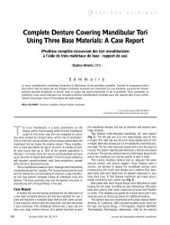
Figure 5: Moderate inclination of the<br />
right-side implant is evident in a frontal<br />
panoramic view.<br />
––––––– Point of Care –––––<br />
Figure 6: Teleradiography of the same<br />
patient as depicted in Fig. 5 shows moderate<br />
discrepancy of the implant positions<br />
projected on the sagittal plane.<br />
lations. The device can be positioned on top of the<br />
residual ridge, behind the implants, or it can be<br />
aligned with the bipupilar plane. This manoeuvre<br />
is easy to perform when estimating angulations<br />
projected on the frontal plane but is more difficult<br />
for angulations on the sagittal plane because the<br />
cheeks and lips interfere (Fig. 2).<br />
Laboratory Assessment<br />
The device described above can also be used<br />
to estimate implant angulations on a dental cast,<br />
obtained by pouring an impression of the arch<br />
with dental stone (Figs. 3 and 4). Alternatively, a<br />
protractor can be used, which will yield a more accurate<br />
measurement of the angle.<br />
Radiographic Assessment<br />
Panoramic radiography (Fig. 5) and teleradiography<br />
(Fig. 6) permit evaluation of the direction of<br />
the implants relative to a reference plane, such as<br />
an anatomic or denture occlusal plane, and measurement<br />
of between-implant angulation.<br />
Choice of Attachment System<br />
When the location and alignment of the implants<br />
are adequate, the choice of attachments<br />
should be based on clinical criteria such as the degree<br />
of retention required, the number of implants<br />
and the available prosthetic space.<br />
Figure 7: Electron micrograph shows<br />
that this ball attachment has become<br />
worn after 8 years in function. Note<br />
the position and direction of the worn<br />
surfaces, about 20° to the long axis of<br />
the attachment. (Original magnification<br />
×30.)<br />
Minor Discrepancies in Between-Implant<br />
Angulation<br />
In cases of minor or mild discrepancies in<br />
between-implant angulation, the following principles<br />
should be observed:<br />
• The matrix parts of ball attachments should be<br />
oriented according to a common path of insertion<br />
for the individual abutments before the<br />
application of acrylic.<br />
• Matrix components with special designs to tolerate<br />
between-implant angulation discrepancies<br />
are commonly available. Plastic parts with<br />
specific levels of resiliency, which are designed<br />
to tolerate divergence or convergence between<br />
implants of up to 40°, are available for some<br />
systems, particularly the cylindrical designs.<br />
It should be emphasized that the amount of<br />
wear in cases of between-implant angulation discrepancies<br />
is directly related to the magnitude of<br />
the angle (Fig. 7).<br />
Significant Discrepancies in Between-Implant<br />
Angulation<br />
In cases of significant between-implant angulation<br />
discrepancies:<br />
• For some systems, special attachment abutments<br />
are manufactured with different angulations<br />
to compensate for discrepancies. Some of<br />
these can be rotated before being tightened in<br />
<strong>JCDA</strong> • www.cda-adc.ca/jcda • September 2008, Vol. 74, No. 7 • 625