12Tong abstract - KEK
12Tong abstract - KEK
12Tong abstract - KEK

Create successful ePaper yourself
Turn your PDF publications into a flip-book with our unique Google optimized e-Paper software.
PF 研究会<br />
<strong>KEK</strong> Proceedings 2012-11<br />
October 2012<br />
M<br />
<strong>KEK</strong> 低速陽電子実験施設における陽電子<br />
回折研究および Ps ビーム研究の新展開<br />
New Research Developments at <strong>KEK</strong>-Slow<br />
Positron Facility<br />
―Positron Diffraction and Ps Beam―<br />
2012 年 10 月 3 日・4 日<br />
高エネルギー加速器研究機構<br />
兵頭俊夫 編<br />
High Energy Accelerator Research Organization
High Energy Accelerator Research Organization (<strong>KEK</strong>), 2012<br />
<strong>KEK</strong> Reports are available from:<br />
High Energy Accelerator Research Organization (<strong>KEK</strong>)<br />
1-1 Oho, Tsukuba-shi<br />
Ibaraki-ken, 305-0801<br />
JAPAN<br />
Phone: +81-29-864-5137<br />
Fax: +81-29-864-4604<br />
E-mail: irdpub@mail.kek.jp<br />
Internet: http://www.kek.jp
【目 次】<br />
趣旨説明 兵頭俊夫(<strong>KEK</strong>-PF) ··················· 1<br />
【基調講演】Low Energy Positron: An Ideal Particle for Studying Surface Structure ···················· 2<br />
S. Y. Tong(South Univ. Sci & Tech., China)<br />
反射高速陽電子回折の理論 一宮彪彦(名古屋大学・名誉教授)14<br />
反射高速陽電子回折(RHEPD)の実験 深谷有喜(JAEA) ················· 16<br />
ポジトロニウム負イオンとエネルギー可変ポジトロニウムビーム<br />
長嶋泰之(東京理科大学) ······· 18<br />
ポジトロニウム負イオン光脱離断面積の計算 五十嵐明則(宮崎大学) ··········· 21<br />
TiO2 表面上からの陽電子刺激イオン脱離 立花隆行(立教大学) ··············· 23<br />
放射光による表面電子分光と陽電子回折 松田巌(東居大学) ··················· 26<br />
低速陽電子輝度増強技術と応用 藤浪真紀(千葉大学) ··············· 33<br />
次期放射光源 ERL 計画の現状 河田洋(<strong>KEK</strong>-PF) ················· 35<br />
<strong>KEK</strong> 物構研低速陽電子実験施設の現状 和田健(<strong>KEK</strong>-PF) ····················· 39<br />
陽電子とスピントロニクス 河裾厚男(JAEA) ····················· 43<br />
陽電子回折への期待 高橋敏男(東京大学) ··············· 46<br />
陽電子による固体表面研究への期待 村田好正(東京大学・名誉教授) ··· 50<br />
Outlook of the <strong>KEK</strong>-IMSS Slow Positron Facility 兵頭俊夫(<strong>KEK</strong>-PF) ················· 53<br />
参加者リスト ··········································································································································· 57
tong.sy@sustc.edu.cn<br />
Slow Positron Diffraction and Positron Holography<br />
S Y Tong<br />
Department of Physics<br />
South University of Science and Technology<br />
China<br />
Abstract<br />
In this paper, we compare and contrast the scattering properties of slow<br />
positrons (20 eV to 300 eV) with that of low energy electrons. Particular<br />
emphasis is placed on the suitability of slow positrons in studying surface<br />
structure.<br />
I. Introduction<br />
It would be interesting to ponder why is the positron an ideal particle for<br />
studying surface structure? It is understood that an ideal probe for studying<br />
surface structure should have two basic attributes:<br />
1) That the particle should have a very short mean free path (
2) Because positrons are repelled by the atomic nuclei, the scattering of<br />
slow positrons by atoms resembles the Born approximation. See, for<br />
example, Tong et al., PRL 69, 3654 (1992).<br />
Figure 1 shows the scattering factor of electrons and positrons at 100 eV for<br />
Cu.<br />
(Figure 1)<br />
- 3 -
II. Properties of Electron Scattering<br />
The scattering factor of slow electrons by atoms contains strong angular<br />
anisotropies [Tong et al. PRB 58,10815 (1998)]. Fig. 2 shows the electron<br />
scattering factor of Ni at various energies.<br />
(Figure 2)<br />
- 4 -
III. Lester Germer: The Father of LEED<br />
Born : Chicago, 1896<br />
1917 graduated from Cornell<br />
1927 discovered low energy electron diffraction with S. G. Davisson<br />
I met Lester Germer in the fall of 1969 when I arrived at Cornell University<br />
as a fresh postdoctoral associate. Germer at that time was a Fellow at<br />
Cornell University. He has retired from Bell Labs and was 73 then.<br />
Germer and I spent many Saturday afternoons in my office drinking the<br />
bitter Carlsburg beer that he bought from India. Germer was looking for<br />
someone to develop a multiple scattering theory of LEED and I was looking<br />
for a new problem to work on. In March 1971, I published the first analysis<br />
of LEED using a new multiple scattering theory that I developed [Tong and<br />
Rhodin, PRL 26, 711 (1971)].<br />
Germer was a vivid sportsman. He frequently walked from Ithaca to<br />
Syracuse (74 km). Unfortunately, Germer died in October that same year<br />
while he was rock climbing. I dedicated my essay “ Electron-diffraction for<br />
surface studies- the first 30 years”, ed. C B Duke, North-Holland 1994 to the<br />
memory of Germer, a true pioneer and my mentor in LEED.<br />
IV. Origin of Electron Anisotropies<br />
In 1998, I established two rules: For a given element, the maximum number<br />
of dips in the scattering factor ∣f (θ)∣ for electrons, positrons or x-rays<br />
equals (l+1) , where l is the highest bound orbital number.<br />
At each dip of ∣f (θ)∣ , its phase jumps by near π. [Tong et al. Phys<br />
Rev B 58, 10815, (1998)].<br />
- 5 -
Fig 3 shows electron angular anisotropies for C, Si, Ga at 100 eV and Pb at<br />
300 eV.<br />
(Figure 3)<br />
As there is no bound orbital for positrons and photons in atoms, there can be<br />
no angular anisotropy in their scattering factor. Fig 4 shows the radial plot of<br />
the magnitude of the scattering factor for electrons, positrons and photons at<br />
- 6 -
1.3 Angstrom wavelength. For the radial scale, each circular ring is 0.25<br />
angstrom. [Tong et al. Phys Rev B 58, 10815, (1998)].<br />
(Figure 4)<br />
V. Forward Focusing (Slow Electrons) vs Forward Shadowing (Slow<br />
Positrons)<br />
In the forward (zero angle) direction, the intensity enhancement factor is<br />
given by [Poon and Tong PRB 30, 6211, (1984)]:<br />
- 7 -
(Figure 5)<br />
Because Re f(0) is positive for electrons,<br />
χ electron (0) = 3.14<br />
On the other hand, Re f(0) is negative for positron scattering,<br />
[Li and Tong, Surf. Sci. Lett., 281, L347 (1993)].<br />
- 8 -
(Figure 6)<br />
VI. Linear LEED vs Linear LEPD<br />
The linear method [Wander et al. PRB 46, 9897 (1992)] searches for a global<br />
minimum in a “large” area (0.5Å x 0.5Å). It requires fully dynamical<br />
calculations at nN structures rather than N n structures, where n is the number<br />
of independent parameters and N is the number of variations considered in<br />
each parameter.<br />
The amplitude in the linear approximation is given by:<br />
- 9 -
(Figure 7)<br />
A test case for the linear method is the structure of the Si(111)-(2x1) pi-chain<br />
model. There are:<br />
Number of variables: 36<br />
36x5 calculations vs 5 36 calculations (see fig 8).<br />
(Figure 8)<br />
How well does the linear method work for LEED vs LEPD? [S Y Tong SRL 7,<br />
21 (2000)]. Fig 9 shows results of linear method vs fully dynamical method<br />
for electrons (left) and positrons (right).<br />
- 10 -
(Figure 9)<br />
VII. Positron Holography: Inverting Experimental Data for Structure<br />
Various forms of diffraction holography require that the scattering factor is<br />
“isotropic” and no sharp jumps in its phase. [Tong et al. SRL 1, 303 (1994)].<br />
- 11 -
(Figure 10)<br />
Inversion of diffraction data [S. Y. Tong, Advances in Physics 1, 135, (1999)]<br />
is given by:<br />
- 12 -
(Figure 11)<br />
The real space image for Cu(001) is shown in fig 12 [Tong et al. PRL 69,<br />
3654 (1992)].<br />
VIII. Conclusions:<br />
(Figure 12)<br />
Slow positron diffraction offers a number of unique properties, making this<br />
technique supremely suitable for studying surfaces.<br />
Eighty five years after the discovery of low energy electron diffraction and<br />
twenty years after theoretical speculations about the merits of slow positron<br />
diffraction, the research at <strong>KEK</strong> and other similar facilities around the globe<br />
offer a long awaited “light” at the end of the tunnel.<br />
- 13 -
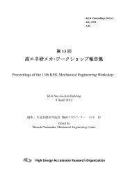
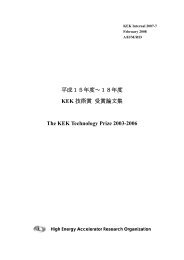
Specular Intensity (arb. units)<br />
RHEPD intensity from Si(111)(1x1)-H surface for 15keV positrons.<br />
exp.<br />
(d)<br />
(c)<br />
(b)<br />
(a)<br />
0 1 2 3 4 5<br />
Glancing Angle (deg)<br />
(d)<br />
(c)<br />
(b)<br />
(a)<br />
Si H<br />
A. Kawasuso et al.<br />
PRB61(2000)2102.<br />
Temperature dependence of RHEPD<br />
intensities from the Si(111)7x7<br />
1<br />
Fukaya et al. PRB 70, 245422 (2004)<br />
Calculated intensities for surface Debye<br />
temperature of 300K with bulk Debye<br />
temperatures of 300K (black circle) and<br />
600K (white square).<br />
At the total reflection condition, glancing<br />
angles θare 1.0 and 1.6, intensities are<br />
mostly the same for different bulk Debye<br />
temperatures, but out of the region, θ=<br />
3.5, the intensities depend largely for the<br />
bulk Debye temperatures.<br />
Structural analysis of Si(111)7x7 surface<br />
by RHEPD pattern<br />
Total reflection positron diffraction pattern<br />
from Si(111)7x7 surface<br />
K.Hayashi et al.<br />
Surf. Sci. 600, 4426 (2006)<br />
Experimental Result and Dynamical Calculation Result<br />
519-beam calculation<br />
Diffraction spots <br />
Experimental<br />
intensities of<br />
diffraction spots<br />
<br />
Calculation<br />
using bulk<br />
atomic<br />
potential<br />
R=7%<br />
Calculation<br />
using modified<br />
potential<br />
R= 4.4%<br />
A ad=1.2<br />
A rest=0.6.<br />
<br />
<br />
<br />
<br />
<br />
<br />
<br />
<br />
<br />
<br />
<br />
<br />
<br />
<br />
3<br />
5<br />
Good agreement<br />
Good agreement<br />
Modified potential: Electron distributions of adatoms are expanded<br />
7<br />
and those of rest atoms are compressed.<br />
- 15 -<br />
E <br />
eV B<br />
eV A<br />
by adsorbed layer.<br />
<br />
<br />
<br />
Total reflection region<br />
<br />
<br />
Adsorbed<br />
layer<br />
Dip appears.<br />
z<br />
Bulk<br />
<br />
<br />
A dip appears at the total<br />
reflection region for<br />
bulk layers due to<br />
absorption effect in the<br />
adsorbed layer.<br />
Temperature dependence of RHEPD<br />
intensities from the Si(111)7x7<br />
Experimental results<br />
Fukaya et al. PRB 70, 245422 (2004)<br />
Surface Debye Temperature:<br />
310 K<br />
Root mean square of atomic vibration amplitude:<br />
0.014 nm at room temperature.<br />
0.025 nm at surface phase transition temperature<br />
of Si(111) at about 1000 K.<br />
Spot profiles of the TREPOD pattern.<br />
Gaussian decomposition<br />
Bulk Debye Temperature:<br />
600 K<br />
Root mean square of atomic vibration amplitude:<br />
0.02 nm at boiling temperature of silicon.<br />
4<br />
Electron distributions of adatoms and rest atoms on the<br />
Si(111)77 surface are determined by the intensity analysis<br />
of the RHEPD pattern using the modified potential.<br />
Compressed electron distribution (roughly 20%)<br />
or a little more electrons (a little ionized).<br />
2<br />
Zero Laue zone<br />
1/7 Laue zone<br />
Expanded electron distribution<br />
(roughly 10%)<br />
6<br />
8
反射高速陽電子回折の実験<br />
Reflection high-energy positron diffraction (RHEPD): Experiment<br />
深谷有喜 1 ,前川雅樹 1 ,望月出海 1 ,和田健 2 ,兵頭俊夫 2 ,河裾厚男 1<br />
Yuki Fukaya 1 *, Masaki Maekawa 1 , Izumi Mochizuki 1 , Ken Wada 2 , Toshio Hyodo 2 , and<br />
Atsuo Kawasuso 1<br />
1 Advanced Science Research Center, Japan Atomic Energy Agency, Takasaki, Gunma 370-1292, Japan<br />
2 Institute of Material Structural Science, Tsukuba, Ibaraki 305-0801, Japan<br />
*e-mail: fukaya.yuki99@jaea.go.jp<br />
1. はじめに<br />
反射高速陽電子回折(RHEPD)法は、10-<br />
20 kV に加速した陽電子ビームを結晶表面に<br />
低角度で入射させ、回折した陽電子の強度<br />
分布から表面の原子配列を決定する手法で<br />
ある。RHEPD では、陽電子がプラスの電荷<br />
を持つことにより、最表面で全反射回折を<br />
起こすことが最大の特徴である[1]。この全<br />
反射回折を利用すると、最表面の原子配列<br />
や熱振動状態をバルクの影響なしに知るこ<br />
とができる。1992 年、一宮により表面研究<br />
における RHEPD 法の有用性が理論的に指摘<br />
された[1]。この有用性を実証するために、<br />
我々は 22 Na 線源を用いて RHEPD 装置の開<br />
発を行い[2-4]、様々な表面超構造の原子配<br />
置[5]や相転移メカニズム[6,7]、また最表面<br />
原子の熱振動状態[8]や、表面プラズモン励<br />
起過程[9]の解明に適用してきた。<br />
RHEPD 法の更なる高度化を目指し、2010<br />
年より、高エネルギー加速器研究機構<br />
(<strong>KEK</strong>)の低速陽電子実験施設(SPF)にお<br />
いて、電子線形加速器(LINAC)を利用し<br />
た新たな RHEPD 装置の開発に着手した[10]。<br />
始めに、コリメーターを用いたビーム形成<br />
を行い、従来の線源法に比べ約 14 倍の反射<br />
強度を得ることに成功した[11]。2012 年より、<br />
入射陽電子ビームの高輝度化を図るため、<br />
陽電子の再放出現象を利用した輝度増強法<br />
の開発に着手した。これにより、LINAC を<br />
用いて生成した高強度陽電子のエネルギー<br />
単色化と平行化を行い、結果として、<br />
Si(111)-7×7 表面からの鮮明な回折パターン<br />
と従来の 44 倍の反射強度を得ることに成功<br />
した。<br />
2. 実験<br />
実験は、高エネルギー加速器研究機構<br />
(<strong>KEK</strong>)低速陽電子実験施設(SPF)にて行<br />
った。高強度の陽電子ビームは、LINAC を<br />
用いた対生成により発生させ、ヘルムホル<br />
ツコイルを用いて RHEPD チャンバーまで輸<br />
送させた。回折パターンは、マイクロチャ<br />
ンネルプレートと CCD カメラを用いて撮影<br />
した。ロッキング曲線は、マニピュレータ<br />
ーを用いて試料を 6.0°まで 0.1°間隔で回転さ<br />
せることにより測定した。<br />
- 16 -<br />
本研究では、テスト基板として Si(111)表<br />
面を用いた。Si(111)表面は表面科学の分野<br />
で標準的な試料であり、清浄表面では 7×7<br />
超構造を形成するため、超構造由来の多数<br />
の回折スポットが発現する。これらの微弱<br />
な回折スポットを観測できることが、本実<br />
験装置の性能をはかるのに必要である。<br />
Si(111)基板は鏡面研磨された n 型の Si(111)<br />
ウエハー(比抵抗:1-10 Ωcm)から短冊状<br />
に切り出したものを使用した。超高真空チ<br />
ャンバー内にて、1200 °C で数回フラッシン<br />
グを行うことにより、Si(111)-7×7 清浄表面<br />
を得た。<br />
3. 結果と考察<br />
3.1 陽電子ビームの高輝度化<br />
RHEPD 強度の高精度測定には、入射陽電<br />
子ビームの高いフラックスに加えて、エネ<br />
ルギー幅の低減が要求される。本研究では、<br />
陽電子の再放出現象を利用して、陽電子ビ<br />
ームのエネルギー幅の大幅な低減を図った。<br />
電子の反粒子である陽電子にとって、結<br />
晶の仕事関数が負となるものが存在する。<br />
例えば、タングステン(W)薄膜に陽電子<br />
が打ち込まれると、熱振動と同程度のエネ<br />
ルギーまで減速した後、真空中に自発的に<br />
放出される。その再放出陽電子を目的の電<br />
圧まで加速させることにより、単色化した<br />
陽電子ビームを得ることができる。<br />
始めに、再放出陽電子の引き出しと収束<br />
を行う 3 段の電極から構成される輝度増強<br />
チャンバーを作製し、RHEPD チャンバーの<br />
前段に設置した。10 kV に昇圧させた W 薄<br />
膜(厚さ 100 nm)に 15 kV の陽電子ビーム<br />
を入射させ、ガイド磁場から解放された陽<br />
電子ビームの強度、ビーム径、エネルギー<br />
幅などの特性評価を行った。エネルギー分<br />
析器を導入し、輝度増強後の陽電子ビーム<br />
のエネルギー幅を測定した。結果として、<br />
10 keV のビームエネルギーに対して、輝度<br />
増強前で半値幅 110 eV であったエネルギー<br />
幅が、輝度増強後では 8 eV まで大幅に低減<br />
することができた。可干渉距離はエネルギ<br />
ー幅に反比例するため、この結果は可干渉<br />
性が約 14 倍向上したことに対応する。また、<br />
輝度増強後の陽電子ビームのフラックスと
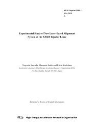
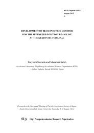
Fig. 1 RHEPD pattern for the Si(111)-7×7 surface<br />
measured by using a new RHEPD apparatus with bright<br />
and intense positron beam based on the LINAC at the<br />
Slow Positron Facility, <strong>KEK</strong>. The incident azimuth of<br />
the positron beam corresponds to the [ 11 2 ] direction.<br />
The glancing angle is set at 2.2°. The indexes at the right<br />
hand side indicate the Laue zone. The pattern shows the<br />
superimposition of the left and right parts.<br />
ビーム径はそれぞれ 10 5 e + /sec 台、0.9 mm<br />
(半値幅)と見積もられた。<br />
3.2 回折パターンとロッキング曲線<br />
輝度増強後の陽電子ビームの特性評価後、<br />
実際の回折パターンの測定を行った。図 1<br />
は、今回開発した高輝度 RHEPD 装置を用い<br />
て測定した、Si(111)-7×7 表面からの RHEPD<br />
パターンである。これまでの線源を用いた<br />
RHEPD 実験では観測することのできなかっ<br />
た、高次の分数次スポットを観測できるよ<br />
うになった。<br />
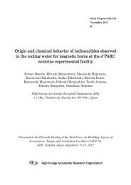
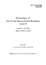
図 2 は、Si(111)-7×7 表面からの RHEPD ロ<br />
ッキング曲線の測定結果である。比較のた<br />
め、以前の線源法を用いて測定した Si(111)-<br />
7×7 表面からの RHEPD ロッキング曲線も示<br />
した。RHEPD 強度は、測定時間で規格化し<br />
たものを示している。今回の高輝度化した<br />
陽電子ビームを用いて測定したロッキング<br />
曲線は非常にスムースであり、全反射領域<br />
や低視射角の 111 ブラッグピークに加え、<br />
高い視射角領域にある強度の弱い 333、444、<br />
555 ブラッグピークも精度よく測定すること<br />
ができた。今回得られた反射強度は、線源<br />
法の 44 倍に達した。現在、陽電子ビームの<br />
収束性の向上などを行い、輝度の更なる向<br />
上を目指している。<br />
今後は、この高輝度化した陽電子ビーム<br />
を用いて、表面科学分野で重要な表面構造<br />
の解明に適用するとともに、陽電子の単純<br />
な散乱過程を最大限に利用して、回折強度<br />
分布から実空間の原子座標を得る、表面超<br />
構造の直接決定法を開発する予定である。<br />
References(参考文献)<br />
[1] A. Ichimiya: Solid State Phenom. 28&29, 143<br />
(1992/93).<br />
[2] A. Kawasuso and S. Okada: Phys. Rev. Lett. 81,<br />
2695 (1998).<br />
- 17 -<br />
RHEPD intensity (arb. units)<br />
Total 111<br />
reflection 222<br />
333<br />
444<br />
555<br />
0 1 2 3 4 5 6<br />
Glancing angle (deg)<br />
Fig. 2 RHEPD rocking curves of specular spots for the<br />
Si(111)-7×7 surfaces measured by using a 22 Na- and<br />
LINAC-based RHEPD apparatus. The incident azimuth<br />
of the positron beam corresponds to the [ 11 2 ] direction.<br />
The indexes at the top of the figure denote the positions<br />
of the Bragg reflections. The critical angle for total<br />
reflection is estimated to be 2.0° via Snell’s law.<br />
[3] A. Kawasuso, Y. Fukaya, K. Hayashi, M.<br />
Maekawa, S. Okada, and A. Ichimiya: Phys. Rev. B<br />
68, 241313 (2003).<br />
[4] A. Kawasuso, T. Ishimoto, M. Maekawa, Y.<br />
Fukaya, K. Hayashi, and A. Ichimiya: Rev. Sci.<br />
Instrum. 75, 4585 (2004).<br />
[5] Y. Fukaya, A. Kawasuso, and A. Ichimiya: Surf.<br />
Sci. 600, 3141 (2006).<br />
[6] Y. Fukaya, A. Kawasuso, and A. Ichimiya: Phys.<br />
Rev. B 75, 115424 (2007).<br />
[7] Y. Fukaya, M. Hashimoto, A. Kawasuso, and A.<br />
Ichimiya: Surf. Sci. 602, 2448 (2008).<br />
[8] Y. Fukaya, A. Kawasuso, K. Hayashi, and A.<br />
Ichimiya: Phys. Rev. B 70, 245422 (2004).<br />
[9] Y. Fukaya, A. Kawasuso, and A. Ichimiya: Phys.<br />
Rev. B 79, 193310 (2009).<br />
[10] 課題番号:2010G652、実験責任者:深谷<br />
有喜、課題名:高輝度陽電子ビームを用いた<br />
反射高速陽電子回折実験<br />
[11] K. Wada, T. Hyodo, A. Yagishita, M. Ikeda, S.<br />
Ohsawa, T. Shidara, K. Michishio, T. Tachibana, Y.<br />
Nagashima, Y. Fukaya, M. Maekawa, and A.<br />
Kawasuso: Eur. Phys. J. D 66, 37 (2012).
Positronium negatives ion and an energy-tunable<br />
positronium beam<br />
<br />
<br />
Y. Nagashima<br />
Tokyo University of Science, Japan<br />
(Ps )<br />
e e + e <br />
H <br />
Ps <br />
e Ps 0.33eV<br />
37.13eV<br />
e + e 5.5a 0<br />
479ps<br />
2<br />
<br />
Ps <br />
(By coating alkali metals onto the surface,<br />
the efficiency increases dramatically.)<br />
~ 1.5%<br />
Ps <br />
Effect of alkali metal coating for the Ps emission<br />
<br />
Change of for tungsten by alkali metal coating<br />
Kiejna and Wojciechowski,<br />
Prog. in Surf. Sci. 11 (1981) 293<br />
D <br />
<br />
<br />
Ps <br />
2<br />
D<br />
D decreases by alkali metal coating<br />
due to the surface dipole reduction.<br />
<br />
2<br />
D 7.<br />
13eV<br />
<br />
Ps <br />
The fraction of conduction electrons<br />
available for the Ps production increases.<br />
Ps <br />
Ps emission efficiency increases.<br />
- 19 -<br />
Ps <br />
The energy required for Ps emission<br />
e <br />
2 7.<br />
13eV<br />
Ps <br />
e + <br />
Ps 3<br />
<br />
(The energy required to break up<br />
Ps into three isolated particles)<br />
(W) 1eV<br />
<br />
Ps<br />
Ps <br />
(Ps is emitted from the surface spontaneously.)<br />
< 0.01%<br />
e e <br />
Energy levels of e and e + near metal surface<br />
<br />
D<br />
<br />
<br />
D<br />
e e + <br />
(Achcroft and Mermin) (Schultz and Lynn, Rev. Mod. Phys. 60 (1988) 701)<br />
e : e + <br />
D<br />
: <br />
<br />
D<br />
e<br />
<br />
D<br />
<br />
e + <br />
Ps<br />
2<br />
<br />
<br />
2 7.<br />
13eV<br />
Ps <br />
D<br />
:<br />
Ps <br />
Effect of alkali metal coating for the Ps emission<br />
NaPs <br />
<br />
Na is the best alkali metal<br />
for the Ps production.<br />
carbon foil<br />
clean W<br />
Terabe, Michishio, Tachibana and Nagashima, New J. Phys. 14 (2012) 015003
Ps<br />
Ps <br />
Ps photodetachment experiment<br />
e + :<br />
(<strong>KEK</strong> Linac)<br />
12ns<br />
50pps<br />
<br />
:<br />
Q-switched Nd: YAG<br />
(Spectra Physics GCR290)<br />
1064nm<br />
(1.165eV)<br />
12ns<br />
25pps<br />
10W<br />
(Michishio, Tachibana, Terabe, Igarashi, Wada, Hyodo, Kuga, Yagishita, Hyodo and Nagashima<br />
Phys. Rev. Lett. 106 (2011) 153401)<br />
Ps Ps<br />
Detection of Ps produced by the Ps photodetachment<br />
Michishio et al.,<br />
Appl. Phys. Lett. 100 (2012) 254102<br />
Ps<br />
Application of the energy tunable Ps beam<br />
Grazing Incidence Fast Ps Diffraction (GIFPsD)<br />
or Reflected High Energy Ps Diffraction (RHEPsD)<br />
Insulator<br />
<br />
?<br />
<br />
, <br />
<br />
<br />
<br />
<br />
<br />
<br />
m Ps
(Calculation of the photo-detachment cross sections of Ps- )<br />
(outline)<br />
1. (Theory)<br />
1.1 1.1 12<br />
12<br />
(One andtwophotodetachment)<br />
1.2 <br />
(Atomic (Atomicorbitalclosecouplingmethod)<br />
orbital close coupling method)<br />
(Results)<br />
21O 2.1Onephotondetachmentcrosssection<br />
h t d t h t ti<br />
2.2Twophotondetachmentcrosssection<br />
<br />
(Univ (Univ. of Miyazaki, Miyazaki Akinori Igarashi )<br />
Igarashi,Shimamura,Toshima<br />
Michishio etal.<br />
NJPhys2 N.J.Phys.2 17 17(2000) (2000) Phys.Rev.Lett.106,153401(2011)<br />
y , ( )<br />
9<br />
- 22 -<br />
Summary<br />
8<br />
13
TiO 2 表面上からの陽電子刺激イオン脱離<br />
Positron stimulated ion desorption from TiO 2(110)<br />
立花隆行 1 *、平山孝人 1 、長嶋泰之 2<br />
Takayuki Tachibana 1 , Takato Hirayama 1 *, and Yasuyuki Nagashima 1<br />
1<br />
Department Physics, Rikkyo University, 3-34-1 Toshima, Tokyo 171-8501, Japan.<br />
2<br />
Department Physics, Tokyo University of Science, 1-3 Kagurazaka, Shinjuku, Tokyo 162-8601, Japan<br />
We observed positron stimulated ion<br />
desorption from TiO2 (110). Desorbed O +<br />
ions were detected at an incident energy<br />
below the threshold for electron stimulated<br />
O + desorption. This result suggests that the<br />
O + ion desorption were induced by the<br />
positron-electron annihilation on the surface<br />
of TiO2.<br />
固体表面に低速の電子線や真空紫外光<br />
が入射したとき、表面を構成する原子や分<br />
子、あるいはイオンが真空中に脱離するこ<br />
とがある。この現象は電子遷移誘起脱離<br />
(DIET: Desorption Induced by Electronic<br />
Transitions) と呼ばれ、表面近傍での電子<br />
的な励起が緩和に至るまでの動的過程の<br />
理解を目的として、そのメカニズムの解明が<br />
進められてきた。<br />
一方、低速陽電子が固体に入射すると、<br />
その一部は熱化した後に表面まで到達し、<br />
表面原子の電子と対消滅をすることがある。<br />
対消滅の相手となるのは伝導電子や価電<br />
子である割合が高いが、内殻電子とも消滅<br />
をする。この結果、対消滅後には表面原子<br />
のイオン化や、内殻正孔生成からオージェ<br />
崩壊を経由した多電子励起状態が形成さ<br />
れることになる。すなわち、陽電子と固体と<br />
の相互作用に特有のDIETが引き起こされ<br />
る可能性がある [1]。本研究では、低速の<br />
陽電子ビームをTiO2(110)に入射し、飛行<br />
時間法を用いて試料表面から脱離するイ<br />
オンの観測をおこなった。陽電子ビーム源<br />
には、東京理科大学の低速陽電子発生装<br />
置を用いた。試料には、電子線や光子入<br />
射によるDIETの機構が よく理解されてい<br />
る [2] TiO2(110)を用いた。<br />
測定結果を Fig. 1 に示す。図中に表記し<br />
た値は陽電子の入射エネルギーである。各<br />
*e-mail: tachibana (at) rikkyo.ac.jp<br />
- 23 -<br />
スペクトルは、測定時間と消滅γ線のカウ<br />
ント数で規格化をしてある。2.4μs 付近に確<br />
認出来るピークは、飛行時間から O + イオン<br />
の信号であることがわかった。<br />
電子線照射の場合、O + イオンが脱離す<br />
るための入射エネルギー閾値は~34eV で<br />
あることが知られている [2]。今回それより<br />
低い陽電子入射エネルギーでも O + イオン<br />
の脱離が観測された。この結果は、陽電子<br />
-電子対消滅によって O + イオンの脱離が<br />
誘起されたことを示唆する。<br />
Signals (arb. units)<br />
0<br />
O +<br />
2<br />
TOF (µs)<br />
4<br />
103eV<br />
58eV<br />
33eV<br />
26eV<br />
24eV<br />
Fig. 1 TOF spectra of desorbed ions from TiO 2 (110)<br />
References(参考文献)<br />
[1] Y. Terashima, et al.: J. Phys. C, 14, L349 (2002).<br />
[2] Lee, Z. Zhang, and J.T. Yates Jr.: Phys. Rev. B 79,<br />
081408(R) (2009).<br />
6
• <br />
<br />
<br />
<br />
<br />
- -<br />
• <br />
1Auger<br />
<br />
<br />
<br />
<br />
<br />
• <br />
• <br />
<br />
<br />
<br />
<br />
- 24 -<br />
<br />
- -<br />
• 20121<br />
<br />
<br />
• 201211<br />
<strong>KEK</strong><br />
<br />
(1) Excitation<br />
Ionization<br />
<br />
• <br />
<br />
• <br />
<br />
(2) Decay<br />
<br />
<br />
(3) Desorption<br />
• <br />
<br />
2<br />
<br />
<br />
<br />
<br />
• 105 e + / s<br />
<br />
• <br />
•
Si wafer<br />
TiO 2 (110)<br />
Mo holder<br />
TiO 2 (110)<br />
60@800<br />
<br />
<br />
MCP<br />
target<br />
TiO 2(110)<br />
<br />
yields<br />
Deflector<br />
O + <br />
2.5<br />
2.0<br />
1.5<br />
1.0<br />
0.5<br />
0.0<br />
0 40 80 120<br />
positron energy (eV)<br />
O + <br />
<br />
• <br />
• <br />
O + <br />
• <br />
• <br />
• <br />
<br />
• <br />
• <br />
O + <br />
• <br />
• <br />
• <br />
- 25 -<br />
TiO 2(110)<br />
<br />
E=103eV<br />
<br />
<br />
<br />
33.6eV 1)<br />
<br />
<br />
Ti (2s), Ti (2p), Ti (3s) ,Ti (3p), O (1s)<br />
2)<br />
Signals (arb. units)<br />
0<br />
H +<br />
<br />
• <br />
<br />
<br />
<br />
e -<br />
(eV)<br />
1) M.L. Knotek and Peter J. Feibelman, PRL., 40 (1978) 964<br />
2) S. Tanaka et al., Surf. Sci, 451 (2000) 281<br />
TIO 2(110)<br />
<br />
O +<br />
1 2 3 4<br />
TOF (μs)<br />
<br />
400eV<br />
24eV<br />
OH + <br />
• <br />
• <br />
O + <br />
<br />
• <br />
• <br />
• <br />
<strong>KEK</strong><br />
B, 23750023<br />
5
scanning tunneling microscopy, reflection highenergy<br />
positron diffraction and angle resolved<br />
photo-emission spectroscopy, Izumi Mochizuki,<br />
Yuki Fukaya, Atsuo Kawasuso, Ken Wada,<br />
Toshio Hyodo, Koichiro Yaji, Ayumi Harasawa,<br />
and Iwao Matsuda, Phys. Rev. B, accepted.<br />
7. Development of soft X-ray time-resolved<br />
photoemission spectroscopy systemwith a twodimensional<br />
angle-resolved time-of-flight<br />
analyzer at SPring-8 BL07LSU, Manami Ogawa,<br />
Susumu Yamamoto, Yuka Kousa, Fumitaka<br />
Nakamura, Ryu Yukawa, Akiko Fukushima,<br />
Ayumi Harasawa, Hiroshi Kondo, Yoshihito<br />
Tanaka, Akito Kakizaki, and Iwao Matsuda, Rev.<br />
Sci. Instrum. 83, 023109-1, 023109-7 (2012).<br />
- 27 -
Studies on surface systems by using electron spectroscopy<br />
with synchrotron radiation and positron diffraction<br />
Iwao Matsuda<br />
:<br />
The Institute for Solid State Physics,<br />
The University of Tokyo,<br />
JAPAN<br />
合金(Metal Alloy)<br />
electron/atom ratio of electron compounds<br />
Alloys fcc bcc hcp<br />
Hume-Rothery phase<br />
Cu-Zn 1.38 1.48 1.58-1.66 1.78-1.87<br />
Chapter 21, C. Kittel,<br />
Cu-Al 1.41 1.48 1.63-1.77<br />
“Introduction to Solid State Physics”,<br />
Cu-Si 1.42 1.49<br />
(1996)<br />
Ag-Cd 1.42 1.50 1.59-1.63 1.65-1.82<br />
A close relation between the Fermi surface and the Brillouin zone<br />
(electron/atom) (the crystal structure)<br />
Two competing theoretical model<br />
Jones theory vs Pseudopotential approach (Pair potential interpretation)<br />
Jones theory for alloying<br />
Cu 5Zn 8<br />
(-brass)<br />
FE<br />
NFE<br />
Formation of metal alloys<br />
of the electron compounds<br />
Any metallic surface superstructure with<br />
electron compound nature?<br />
2-D Square lattice<br />
Fermi ring<br />
(2e<br />
2-D Hexagonal lattice<br />
- /cell)<br />
Reduction of electrons at the highest kinetic energy<br />
FE: Free Electron model, NFE: Nearly Free Electron model<br />
NFE Pseudo-gap<br />
FE<br />
Fermi wavenumber,<br />
Fermi surface<br />
Crystal structure<br />
2e - /cell<br />
=> Metallic<br />
2e - /cell<br />
Insulating<br />
Complete gap-opening<br />
Not pseudo-gap!!<br />
- 28 -<br />
Physical properties at a surface<br />
Surface atomic structure Surface electronic structure<br />
Diffraction Spectroscopy<br />
陽電子回折 Positron Diffraction 光電子分光 Photoemission spectroscopy<br />
Mystery of the 2-D ordered metal alloy on a surface<br />
Introduction of our time-resolved photoemission station<br />
at synchrotron radiation facility<br />
合金(Metal Alloy)<br />
Pair potential interpretation<br />
(long-range interaction mediated by conduction electrons)<br />
w: individual ion<br />
pseudopotential<br />
2 2<br />
*<br />
k<br />
S ( q)<br />
S(<br />
q)<br />
k | w | k q k q | w | k <br />
E(<br />
k)<br />
k | w | k <br />
2 2<br />
2<br />
2m<br />
q / 2m[<br />
k ( k q)<br />
]<br />
Band structure energy Ebs =ΣS(q)*S(q)F(q)<br />
Fourier Transform<br />
1<br />
1<br />
E bs Vpair<br />
( ri<br />
rj<br />
) F(<br />
q)<br />
2N<br />
i<br />
j<br />
N q<br />
Ion-pair potential(structure dependent)<br />
2<br />
sin( 2k<br />
V pair ( ri<br />
rj<br />
) F(<br />
q)<br />
exp( iq<br />
(<br />
ri<br />
rj<br />
))<br />
Fd<br />
2δ<br />
F )<br />
V<br />
N<br />
3D<br />
<br />
3<br />
i<br />
j<br />
( kF<br />
d)<br />
Ion pair-interaction via the 3-D Friedel oscillation<br />
Surface Metal Alloy (2-D Metal Alloy) on Semiconductor Substrate<br />
Ag: 1ML Ad: 0.1~ 0.2ML<br />
Si(111)7×7<br />
Si(111)√3×√3-Ag<br />
470~870K < 200~300 K<br />
Si(111)√3×√3-Ag<br />
Si(111)√21×√21-(Ag, Ad)<br />
2012/10/04<br />
Si(111)√21×√21-(Ag, Ag)<br />
1
(c)<br />
(b)<br />
(a)<br />
the order of 100 cal/mol<br />
for noble metal alloys<br />
Prog. Mat. Sci. 22, 151 (1978).<br />
k x (Å -1 )<br />
Electron doping<br />
Surface Metal Alloy (2-D Metal Alloy) on Semiconductor Substrate<br />
The √21×√21 phase on Si(111)<br />
Initial surface phase adatom formation total a number of<br />
(coverage) (coverage) temperature coverage valence electrons<br />
I. Matsuda, T. Hirahara et al., Phys. Rev. B71, 235315 (2005).<br />
2-D surface phase<br />
Fermi surface<br />
√3×√3-Ag (1.0 ML) Au (0.1~0.2ML) LT<br />
√3×√3-Ag (1.0 ML) Ag (0.1~0.2ML) LT<br />
1.1~1.2 ML 3/unit cell [1]<br />
1.1~1.2 3 [2]<br />
√3×√3-Ag (1.0 ML) Na (0.1~0.2ML) LT 1.1~1.2 3 [2]<br />
0.2<br />
Si(111)√3× √ 3-Ag<br />
√3×√3-Ag (1.0 ML) K (0.1~0.2 ML) LT 1.1~1.2 3 [3]<br />
0.0<br />
√3×√3-Ag (1.0 ML) Cs (0.1~0.2 ML) LT<br />
√3×√3-Au (~0.9 ML) Ag (0.2~0.3 ML) HT<br />
1-D surface phase<br />
1.1~1.2 3 [3]<br />
1.1~1.2 3 [4]<br />
-0.2<br />
5x2-Au (0.4~0.5 ML) Ag (~0.7 ML) HT 1.1~1.2 3 [5]<br />
0.2<br />
3x1-Ag (0.3ML) Au(0.8ML) HT 1.1~1.2 3 [6]<br />
k x (Å -1 )<br />
k x (Å -1 )<br />
0.0<br />
-0.2<br />
0.2<br />
Si(111)√21× √ 21-Ag<br />
0.0<br />
-0.2<br />
E F1<br />
0.0<br />
0.5 1.0<br />
ky (Å-1 )<br />
Jones theory for surface (2-D) alloying<br />
Energy difference = ∫ E•DOSNFE (E)dE - ∫ E•DOSFE 0<br />
(E)dE<br />
0<br />
E F2<br />
NFE Energy FE Energy<br />
-100 meV /unit cell<br />
(- 51 cal/mol)<br />
Energy stabilization but the minimum<br />
at two electrons (insulating)<br />
1.5<br />
-65 meV,<br />
(- 33 cal/mol)<br />
Photoemission<br />
Fermi surface of a √21×√21<br />
Free electron surface (ring)<br />
The crystal phase has the constant electron/atom ratio<br />
electron compound nature<br />
[1] J. N. Crain et al., Phys. [2]I. Matsuda et al., Phys. [3]H. M. Zhang et al.,Phys. [4]J. Yuhara et al., Surf. [5] I. Matsuda et al., Phys.<br />
Rev. B 66, 205302(2002). Rev.B 71, 235315 (2005). Rev. B 70, 245301 (2004). Sci. 326, 133 (1995). Rev B 82, 165330 (2010).<br />
Pair potential interpretation<br />
Ion pair-interaction via the 2-D Friedel oscillation<br />
band structure energy:<br />
n=1 : kF=0.153[Å-1 ]<br />
n=2 : kF=0.216[Å-1 ]<br />
n=3 : kF=0.265[Å-1 kF ]<br />
n: electrons/unit cell<br />
d(d’)<br />
Distance between two<br />
adatoms<br />
(up to the 11 th nearest<br />
neighbors)<br />
Structure analysis of the √21x√21 phase Positron Diffraction<br />
Ag: 1ML Ag: 0.1~ 0.2ML<br />
Si(111)7×7<br />
Si(111)√3×√3-Ag<br />
470~870K LT<br />
J. Nogami et al,<br />
SS 306 (1994) 81.<br />
X. Tong et al,<br />
PRB55(1997)1310.<br />
A. Ichimiya et al,<br />
SRL1(1994) 1<br />
H. Tajiri et al,<br />
SS493(2001)214<br />
大きな銀三角格子<br />
7箇所<br />
Siトリマー<br />
7箇所<br />
吸着可能位置数:21箇所<br />
吸着原子数 :3~5個<br />
Si(111)√21×√21-(Ag, Ag)<br />
小さな銀三角格子<br />
7箇所<br />
21C 3=1330通り<br />
21C 4=3990通り<br />
21C 5=20349通り<br />
- 29 -<br />
Δ<br />
<br />
K<br />
M<br />
kF 2012/10/04<br />
√21×√21<br />
SBZ<br />
[6] F. Nakamura et al.,<br />
submitted.<br />
2sin(<br />
δF<br />
) 2 sin( 2kF<br />
d 2δ<br />
F )<br />
ε<br />
F ( )<br />
π ( k d)<br />
E 2<br />
ionpairs F<br />
the √21x√21 phase<br />
Photoemission Fermi surface mapping<br />
Structure analysis<br />
the √3x√3 phase<br />
2
Positron Diffraction<br />
RHEPD intensity (arb. units)<br />
TR<br />
(222)<br />
(111) (333) (444)<br />
: exp<br />
: cal<br />
(0 0)<br />
(1/3 1/3)<br />
(2/3 2/3)<br />
0 1 2 3 4 5<br />
Glancing angle (deg)<br />
6<br />
吸着サイト: 大きな Ag三角格子<br />
吸着数 : 3箇所<br />
Model 1 Model 2 Model 3<br />
Model 4 Model 5<br />
5通りが選別されるが<br />
有意差はない<br />
Ag<br />
Si<br />
Positron Diffraction<br />
__ __<br />
(20/21 17/21)<br />
-5 -4 -3 -2 -1 0 1 2 3 4 5<br />
Position in the 1/7-th Laue zone(Å -1 )<br />
Positron Diffraction Positron Diffraction<br />
RHEPD intensity (arb. units)<br />
-5 -4 -3 -2 -1 0 1 2 3 4 5<br />
Position in the 1/7-th Laue zone(Å -1 )<br />
Positron Diffraction<br />
RHEPD<br />
X-ray (SS01)<br />
STM (SS98)<br />
STM (SRL94)<br />
STM (SS94)<br />
EXPR<br />
Y.Fukaya et al. e-J. Surf. Sci. Nanotech. 7, 432 (2009).<br />
Compatible<br />
最適構造をもとに計算した<br />
陽電子回折強度分布<br />
Not compatible<br />
STMやXRDにより決定され<br />
た構造から計算した回折<br />
強度分布<br />
- 30 -<br />
Diffraction intensity (arb. units)<br />
(20/21 17/21)<br />
Model<br />
No.<br />
5<br />
4<br />
3<br />
2<br />
1<br />
exp.<br />
トップAg<br />
下地Ag層<br />
Au:<br />
0.4~0.5ML<br />
Si(111)7×7<br />
790K<br />
Si(111)5×2-Au<br />
Ag: 0.6~ 0.7ML<br />
HT<br />
Core-level photoemission spectra<br />
Y.Fukaya et al. Surf. Sci. 606, 919 (2012).<br />
1/7th Laue-zone<br />
1 nm<br />
2012/10/04<br />
下地Si層<br />
Y.Fukaya et al. Surf. Sci. 600, 3141 (2006).<br />
Si(111)√21×√21-(Ag, Au)<br />
3
Positron Diffraction<br />
Ag: 1ML Cs: 0.1~ 0.2ML<br />
Si(111)7×7<br />
Si(111)√3×√3-Ag<br />
470~870K LT<br />
Δ<br />
Pair potential interpretation<br />
band structure energy:<br />
<br />
2sin(<br />
δF<br />
) 2 sin( 2kF<br />
d 2δ<br />
F )<br />
ε<br />
F ( )<br />
π ( k d)<br />
E 2<br />
ionpairs F<br />
δ F=0.46<br />
π<br />
δ F=0.63<br />
π<br />
Standing wave around a Ag nanocluster<br />
(a precursor of the √21×√21-Ag phase)<br />
東大物性研 長谷川幸雄研<br />
Si(111)√21×√21-(Ag, Cs)<br />
Y.Fukaya et al. Surf. Sci. accepted.<br />
k F=0.265(n=3)<br />
Minimum<br />
at 3 e - /unit cell<br />
- 31 -<br />
Pair potential interpretation<br />
Ion pair-interaction via the 2-D Friedel oscillation<br />
band structure energy:<br />
Δ<br />
<br />
2sin(<br />
δF<br />
) 2 sin( 2kF<br />
d 2δ<br />
F )<br />
ε<br />
F ( )<br />
π ( k d)<br />
E 2<br />
ionpairs F<br />
Alkali metal adatom Noble metal adatom<br />
Phase shift analyses<br />
Alkali metal adatom<br />
δF=0.46π Friedel sum rule, s-wave, +1 charge:<br />
δ F=0.5π<br />
Cs/Cu(111),<br />
Th von Hofe et al. Phys. Rev B 73 245434 (2006).<br />
δ F=(0.43±0.08)π<br />
Noble metal adatom<br />
δF=0.63π Standing wave around a Ag nanocluster<br />
(a precursor of the √21×√21-Ag phase)<br />
Phase shift analyses<br />
Alkali metal adatom<br />
δF=0.46π Distance from Ag adatom [Å]<br />
STM<br />
√21×√21-Ag domain<br />
and Ag nanoclusters<br />
on √3×√3-Ag/Si(111)<br />
2012/10/04<br />
n=1 : kF=0.153[Å-1 ]<br />
n=2 : kF=0.216[Å-1 ]<br />
n=3 : kF=0.265[Å-1 kF ]<br />
n: electrons/unit cell<br />
d(d’)<br />
Distance between two<br />
adatoms<br />
(up to the 11 th nearest<br />
neighbors)<br />
C. Liu et al., Phys. Rev. B 74, 235420 (2006).<br />
Friedel sum rule, s-wave, +1 charge:<br />
δF=0.5π Cs/Cu(111),<br />
Th von Hofe et al. Phys. Rev B 73 245434 (2006).<br />
δF=(0.43±0.08)π STM<br />
√21×√21-Ag domain<br />
Noble metal adatom<br />
and Ag nanoclusters<br />
δF=0.63π on √3×√3-Ag/Si(111)<br />
Standing wave around a Ag nanocluster<br />
(a precursor of the √21×√21-Ag phase)<br />
sin( δ)<br />
LDOS ( ) cos( 2kd<br />
δπ<br />
)<br />
2πkd<br />
δ=(0.61±0.05)π<br />
C. Liu et al., Phys. Rev. B 74, 235420 (2006).<br />
STS<br />
4
The √21×√21 phases, prepared by eight different procedures, show the constant number of<br />
total metal coverage and a number of valence electron, showing surface electron compound<br />
nature.<br />
The Anderson’s idea and the Jones model do find electron stability by the surface<br />
superstructure formation. However, they fails to explain a number of valence electrons and<br />
the experimental band feature.<br />
The pair potential interpretation (the pseudopotential approach) explains all the experimental<br />
results, indicating importance of medium-range interatomic interaction, mediated by the 2-D<br />
surface-state electrons.<br />
The √21×√21 superstructure model<br />
Alkali metal adatom Noble metal adatom<br />
scattered surface<br />
electron wave<br />
surface<br />
electron wave<br />
adatom<br />
phase shift, <br />
I. Matsuda et al., Phys. Rev. B 82, 165330 (2010).<br />
δF=0.46π ns1 δF=0.63π (n-1)d10ns1 - 32 -<br />
Acknowledgements<br />
Y. Fukaya, A. Kawasuso, and A. Ichimiya<br />
2012/10/04<br />
5
低速陽電子輝度増強技術と応用<br />
Brightness Enhancement for a Positron Microprobe and Its Applications<br />
藤浪真紀<br />
M. Fujinami<br />
Dept. of Applied Chemistry & Biotechnology, Chiba University, Yayoi, Inage, Chiba 263-8522, Japan<br />
*e-mail: fujinami(at)faculty.chiba-u.jp<br />
Brightness enhancement is an essential<br />
technique for a formation of a positron<br />
microprobe. We have installed the positron<br />
microprobe and constructed a transmission<br />
positron microscope at <strong>KEK</strong>. In this talk,<br />
the strategy and the performance are given.<br />
Further, the idea on the positron optics for<br />
low energy positron diffraction is discussed.<br />
加速器を利用して陽電子を発生すると<br />
10 6 e + /s と高強度ではあるが,そのビー<br />
ム径は数十 mm となる。したがって,そ<br />
の有効利用のためには輝度増強は必須で<br />
ある。“輝度増強”とは,径を小さくしつ<br />
つ発散角を小さくするという輝度保存則<br />
を克服することである。これは陽電子が<br />
いくつかの物質に対して負の仕事関数を<br />
もつという特有の性質に由来する。表面<br />
近傍 100 nm 付近で熱化した陽電子は,<br />
仕事関数の絶対値(半値幅は熱エネルギ<br />
ー程度)で法線方向に自発的に再放出さ<br />
れる。本発表では,数年前に <strong>KEK</strong> の低<br />
速陽電子実験施設に設置した輝度増強光<br />
学系とそれを利用した透過型陽電子顕微<br />
鏡(Positron transmission microscope, TPM)<br />
の成果を報告する。さらに,低速陽電子<br />
線回折(Low energy positron diffraction,<br />
LEPD)のための光学系を提案する。<br />
<strong>KEK</strong> の陽電子ビームは最高で 35 keV<br />
のエネルギーで静磁場中を約 25 mm のビ<br />
ーム径で輸送される。マイクロビーム化<br />
には輸送用静磁場から陽電子を切り離し,<br />
輝度増強用再減速材に照射し,放出した<br />
陽電子を静電場輸送に変換する必要があ<br />
る。輝度増強には 150 nm 厚の Ni(100)単<br />
結晶を用いて,透過型再減速材方式を採<br />
用した。それにより光学系の単純化,開<br />
発期間の短縮,コスト低減が図られた[1]。<br />
磁場からの陽電子ビームを引き出す際,<br />
焦点位置を透過型再減速材 Ni 薄膜とす<br />
る磁界レンズを利用するこ。それにより<br />
引き出しと集束を同時に達成できる。磁<br />
場を打ち消すために,輸送用ヘルムホル<br />
ツコイルにおいて最終のヘルムホルツコ<br />
イルでは逆方向の磁場を発生するように<br />
する。これは磁界レンズの集束条件を最<br />
適化する効果もあり,35 keV で輸送され<br />
た陽電子ビームを 1/10 の 3 mm 程度に集<br />
- 33 -<br />
束し,磁場フリー領域に取り出すことが<br />
できた。<br />
透過型再減速材利用に必須の条件は,<br />
欠陥や不純物を除去するための高温アニ<br />
ールと表面の清浄化である。そこで,い<br />
ったん高温でアニールし,その後ビーム<br />
ラインの真空装置内で原子状水素処理を<br />
行った。膜厚が 150 nm であると,陽電<br />
子の入射エネルギーや拡散距離を考慮す<br />
ると,5 keV 程度の入射が適当である。<br />
予備実験の結果では,当初の効率は 15%<br />
で,数日で約 10%まで低下したが,その<br />
後は低下はせず安定していた。陽電子は<br />
35 keV 輸送されるので,再減速材 Ni 薄<br />
膜を 30 keV に印加した。<br />
再減速材から垂直方向に再放出された<br />
陽電子は,引出電極,集束電極,加速電<br />
極から構成された静電レンズで静電輸送<br />
される。集束電極電位を調整することに<br />
より 30 keV TPM のクロスオーバー位置<br />
にコリメートビームで入射される。本装<br />
置では,電子銃も 90°方向に取り付けら<br />
れ,磁気プリズムを用いて同一のクロス<br />
オーバー位置を形成でき,透過陽電子像<br />
と電子像を比較できるようにした。両者<br />
の透過像や回折パターンは MCP により<br />
検出した。平成 20 年当時の <strong>KEK</strong> 低速陽<br />
電子実験施設のビーム強度において 10<br />
時間かけて 10,000 倍の透過像,1 時間程<br />
度で回折パターンが取得できた。電子像<br />
との比較を試みたが,その程度の倍率で<br />
は明瞭な差は観察されなかった。一方,<br />
透過率については散乱方向の違いによる<br />
と考えらえる有意な差が認められた[2]。<br />
LEPD の開発は,この TPM の静電ビー<br />
ムを初期ビームとしてもう一段輝度増強<br />
を行い,LEPD の入射ビームとする。<br />
LEPD 像や優位性の一部は Canter らによ<br />
り実証されている[3]が,この高強度化さ<br />
れた <strong>KEK</strong> の低速陽電子実験装置により<br />
さらなる具現化に資する。<br />
References(参考文献)<br />
[1] M. Fujinami et al.: Anal. Sci. 24, 73-79 (2008).<br />
[2] M. Matsuya et al.: Nucl. Instrum. Methods A 645,<br />
102-112 (2011).<br />
[3] G. R. Brandes et al.: Rev. Sci. Instrum. 59, 228-<br />
235 (1988).
3<br />
4.3 m<br />
Positron probe microanalyzer<br />
Brightness enhancement<br />
XY stage<br />
Ge detector<br />
Linac-PPMA<br />
@<br />
RI source<br />
Sample<br />
Objective lens RI-PPMA<br />
<br />
@<br />
Transmission positron microscope<br />
Linac-TPM<br />
@<strong>KEK</strong><br />
30 kV TPM<br />
2.1 m<br />
TEM<br />
(JEOL)<br />
EX<br />
ML<br />
RM<br />
EL<br />
DEF<br />
Sector<br />
CL1<br />
CL2<br />
OL<br />
IL system<br />
PL<br />
e +<br />
35 keV<br />
MCP<br />
e<br />
Electron gun<br />
MCP<br />
-<br />
Specimen<br />
MCP<br />
Microbeam forming section<br />
Transmission electron microscope<br />
Transmission electron microscope<br />
JEM-1011(JEOL)<br />
JEM-1011(JEOL)<br />
TEM<br />
Remoderator<br />
Ni(100) ) 150 nm<br />
Work function<br />
-1.0 eV<br />
35 keV<br />
30 keV<br />
e + & e - diffraction pattern of Au(100) foil<br />
Positron Electron<br />
15 hr<br />
We can succeed in 10,000 times TPM image and the diffraction pattern,<br />
comparable with TEM.<br />
23% S <br />
30 kV<br />
- 34 -<br />
<strong>KEK</strong>-TPM <br />
Ta target (positron source) and<br />
several W foils (moderator)<br />
floated at 35 kV<br />
Linac : 44 MeV, 0.2 GeVmA, 50 Hz<br />
TPM & TEM image of Au(100) foil<br />
16 hours<br />
Resolution : 50 nm<br />
1 μm<br />
4.3 m<br />
Microprobe<br />
TEM<br />
2.1 m<br />
Positron gold thin film<br />
micro grid<br />
Electron<br />
hole<br />
3. Positron probe microanalyzer (PPMA)<br />
The plume induced by the<br />
injected positrons<br />
m <br />
5-25 keV e +<br />
<br />
Thermalization,<br />
Diffusion,<br />
& trap at defect<br />
LEPD<br />
<br />
m<br />
<br />
<br />
511 keV -rays<br />
X10,000<br />
1 μm<br />
m
- 36 -
- 37 -
- 38 -
<strong>KEK</strong> 物構研低速陽電子実験施設の現状<br />
Present status of the <strong>KEK</strong>-IMSS Slow Positron Facility<br />
和田 健<br />
Ken Wada<br />
高エネルギー加速器研究機構物質構造科学研究所<br />
Institute of Materials Structure Science, High Energy Accelerator Research Organization (<strong>KEK</strong>)<br />
The Slow Positron Facility (SPF) at the<br />
Institute of Materials Structure Science<br />
(IMSS), High Energy Accelerator Research<br />
Organization (<strong>KEK</strong>) provides a<br />
high-intensity pulsed slow-positron beam<br />
produced by using a dedicated linac. The<br />
electron-beam energy of the linac is 55<br />
MeV with the operation power of 600 W at<br />
the maximum. The maximum repetition rate<br />
is 50 Hz. It operates in two pulse modes: the<br />
long pulse mode of 1 µs pulse width, and<br />
the short pulse mode of variable 1-10 ns<br />
pulse width.<br />
In October 2010, a new positron<br />
converter and moderator assembly was<br />
introduced, yielding an increase of an order<br />
of magnitude in the intensity of the beam.<br />
The long pulse mode provides 510 <br />
slow-e + /s, and the short pulse mode provides<br />
510 slow-e + /s. The initial beam diameter<br />
is about 20 mm.<br />
The facility consists of two floors. The<br />
dedicated linac and the positron converter<br />
and moderator assembly are on the<br />
basement floor. Currently, there are four<br />
beam-line branches: two of them (SPF-A1,<br />
SPF-A3) lies on the basement floor, and one<br />
branch (SPF-A2) goes up to the deck floor<br />
and comes down vertically, and the last one<br />
(SPF-B1) goes up onto the ground floor.<br />
The positron converter and moderator<br />
assembly is at a high tension of up to 35 kV<br />
with reference to the grounded<br />
slow-positron beam line, and the tension is<br />
adjusted in accordance with the<br />
requirements of individual experiments.<br />
Standardized beam-line-branching units for<br />
the transportation energy of up to 35 keV<br />
allow flexible rearrangements of the<br />
branches.<br />
e-mail: ken.wada@kek.jp<br />
- 39 -<br />
高エネルギー加速器研究機構 (<strong>KEK</strong>)<br />
物質構造科学研究所 (IMSS) の低速陽電<br />
子実験施設 (SPF) では、55 MeV, 600 W<br />
の専用ライナックを用いた高強度の低速<br />
陽電子ビームを共同利用に供している。<br />
ライナックの繰り返し周波数は 50 Hz<br />
で、共同利用実験のニーズにあわせて, パ<br />
ルス幅 1 µs のロングパルスモード<br />
(510 slow-e + /s) と、1 ns から 10 ns<br />
で可変のショートパルスモード (510 <br />
slow-e + /s) を切り替えて運転している。<br />
本施設のビームラインは、1) 高強度の<br />
低速陽電子ビームを供すること、2) 測定<br />
器を含めたビームライン全体がアース電<br />
位のまま、最大 35 keV のエネル ギーで<br />
ビームを輸送できること、3) 標準化され<br />
た分岐ユニットにより、比較的自由にビ<br />
ームラインの分岐ができること、という<br />
特徴を持つ。これらの特徴を生かして, 最<br />
近はポジトロニウム負イオンの分光実験<br />
とそれを応用した可変エネルギーのポジ<br />
トロニウムビームの生成実験、反射高速<br />
陽電子回折 (RHEPD) 実験において, 成<br />
果が上がっている.<br />
本講演では, 当施設の最近の発展状況<br />
及び現状について報告すると共に, 共同<br />
利用実験の概要について報告する.
Ahighintensity,pulsedslowpositronbeamiscreatedbyusingadedicatedlinac.<br />
Apositronconvertorandmoderatorassemblyisathightensionupto35kV.<br />
p y g p<br />
Andthusentireslowpositronbeamlineisgrounded.<br />
TheDedicatedLinac withradiationshieldsoff<br />
e e<br />
e+ e+convertor convertor<br />
andmoderator<br />
Anewpositronconvertor/moderator<br />
(Old) Anorderofmagnitudeincrease (New)<br />
inthebeamintensity<br />
25mthickWfoilarray<br />
Perpendiculartothee p<br />
incident<br />
direction<br />
TwosetsofWfoil(25mthick)lattices<br />
Acascadevoltagesupplytoset<br />
voltagesbetweentheconverter,<br />
thelattice1,thelattice2,and<br />
an anextractiongrid.<br />
extraction grid<br />
K.Wadaetal.:Eur.J.Phys.D,66:37(2012)<br />
AnnealingofWmoderatorwithanelectronbeamwelder<br />
Theelectronbeamweldingmachineused PowerhighenoughtomeltWfoil<br />
for forannealingofthemoderator annealing of the moderator<br />
(meltin (meltingpoint3400)<br />
point 3400)<br />
- 40 -<br />
SchematicviewoftheBeamlines<br />
Th Theslowpositronbeamlinesandexperiment<br />
l i b li d i<br />
stations<br />
SPFA3<br />
SPFB1<br />
SPFA2<br />
(Stationsarenotshown)<br />
B1fl.<br />
Thepartswithdifferentcolorsareelectricallyisolatedfromeachother.<br />
Bottomred:convertorOrangeandgreen:moderators<br />
g g<br />
Blue:extractiongrid<br />
Topred:wehnelt cylinder,samepotentialastheconvertor<br />
ReductionofDopplershiftedrayfromPs <br />
Gnd.fl.<br />
SPFA1<br />
PositroniumnegativeionstationbuiltbythegroupofProf.Nagashima<br />
The photo detachment of the Ps ThephotodetachmentofthePs ion ion with withapulsed25HzNd:YAG a pulsed 25 Hz Nd:YAG laser<br />
Signalswithandwithoutlaserirradiationofthe50Hzslowpositronbeam<br />
DopplershiftedannihilationfromtheacceleratedPs detectedbyGe ditectors
on<br />
stati<br />
Ps <br />
RevisedchamberfordetectingphotodetachedPsdirectlywithanMCParray.<br />
Th Theincidentpositronbeamwasmagneticallybentby45degreesandledtothetarget.<br />
i id t it b ti ll b tb 45d dl dt th t t<br />
Ps wereacceleratedbyanelectrostaticfield,andthenirradiatedbythelaser.<br />
TOFofthePsshowstheaccelerationbeforethephotodetachment.<br />
<br />
Thebeamlinebranchingunit g<br />
<br />
PsTOFstation<br />
Standardizedbeamlinebranchingunit<br />
forupto35keV positronbeam<br />
(SPF-B1) RHEPD station<br />
(without ( a brightness-enhancement g unit) )<br />
<br />
<br />
e+ <br />
<br />
Ironplate Iron Einzel lens<br />
<br />
aperture<br />
<br />
<br />
Collimator<br />
<br />
<br />
<br />
<br />
<br />
RHEPDrockingcurve<br />
22 Nabasedbeam<br />
<strong>KEK</strong>RHEPDT<br />
RHEPDpatternfortheSi(111)7x7surface<br />
using usingthebrightnessenhancementunit(BEU)<br />
the brightness enhancement unit (BEU)<br />
BeforetheBEUinstallation<br />
AftertheBEUinstallation<br />
1/7<br />
Thefractionalspotshavebeenobserved<br />
withthebrightnessenhancedbeam<br />
1<br />
6/7<br />
5/7<br />
4/7<br />
3/7<br />
2/7<br />
- 41 -<br />
AnewBLbranch(SPFA3)forPsbeamdetection<br />
LargemagneticcoilsforthePsbeamstation<br />
The Thenewbeam new beamline linebranchforPs branch for Psbeam beamstation station<br />
Vacuumdegree: 2 10 8 Pa<br />
(SPF-B1) Reflection high-energy positron diffraction (RHEPD)<br />
e+ beam<br />
e+<br />
10~100keV<br />
Lenses<br />
RHEPD Pattern<br />
Sample<br />
Rocking Curve<br />
Anngle<br />
Intensity<br />
Positron<br />
<br />
+<br />
Electron<br />
Positronsaretotallyreflected<br />
Solid<br />
becauseofpositivecrystalpotential.<br />
surface<br />
<br />
<br />
Sensitivetotheatomicarrangement<br />
Atom <br />
andtheeffectsofelectronsandphonons.<br />
d h ff f l d h<br />
SchematicsandpicturesofthebrightnessenhancementunitforRHEPD<br />
Consistingofatransmissionremoderator with100nmWcrystal,andelectrodes.<br />
TheWremoderator wasannealedbythepassageofelectroncurrent.<br />
RHEPD rocking curve<br />
from Si(111) Si(111)-7x7 7x7 surface<br />
(arb. units)<br />
RHEPD R intensity i<br />
Total 111<br />
555<br />
reflection 222 333 444<br />
0 1 2 3 4 5 6<br />
Glancing angle (deg)<br />
<strong>KEK</strong>-SPF with remoderation<br />
<strong>KEK</strong>-SPF without remoderation<br />
22 22Na Na-based based beam
Renewedpositronium timeofflight(PsTOF)station<br />
Smaller Smallerplasticscintillatorsdeliverabettertimeresolution<br />
plastic scintillators deliver a better time resolution<br />
TOFfromthetungstensurface performedbyProf.Nagashima’s group<br />
EnhancementofthePsemissionefficiencyobservedforNacoatedsample<br />
Beamtimeandexperiments in<strong>KEK</strong>SPF<br />
• 2010:beamtime 181days<br />
– Ps Ps experiment experiment(Y.Nagashima (Y Nagashima et etal.) al )<br />
– RHEPDexperiment(Y.Fukaya etal.)<br />
• 2011:beamtime 180days<br />
– Ps experiment<br />
– RHEPDexperiment<br />
• 2012<br />
– Ps experiment<br />
– RHEPDexperiment p<br />
– PsTOFexperiment1(T.Tachibanaetal.)<br />
– PsTOFexperiment2(Wadaetal.)<br />
– Positron Positronimpactinducediondesorptionexperiment(Hirayamaetal.)<br />
impact induced ion desorption experiment (Hirayama et al )<br />
Staffandcurrentusersof<strong>KEK</strong>SPF<br />
• <strong>KEK</strong>SPFstaff<br />
– Slowpositronbeamline<br />
p<br />
• T.Hyodo,K.Wada(April2010),andI.Mochizuki(October2012)<br />
– Dedicatedlinac ofSPF<br />
• T.Shidara,S.Ohsawa,M.Ikeda,andothermembersof<strong>KEK</strong>linac group<br />
• Currentusersof<strong>KEK</strong>SPF<br />
– PsnegativeionandPsTOFexperiment<br />
g p<br />
• Y.Nagashima andhisstudents(TokyoUniversityofScience)<br />
• T.Tachibana(Rikkyo University)<br />
– RHEPDexperiment<br />
• A.Kawasuso,Y.Fukaya,M.Maekawa (JapanAtomicEnergyAgency)<br />
• I.Mochizuki(<strong>KEK</strong>)<br />
– Positronimpactinducediondesorptionexperiment<br />
• T.HirayamaandT.Tachibana(Rikkyo University)<br />
– LEPDexperiment<br />
• T.TakahashiandT.Shirasawa (TheUniversityofTokyo)<br />
• M.Fujinami ( (ChibaUniversity)<br />
hb )<br />
- 42 -<br />
Aclientserversystem<br />
to tocontrolmagneticcoilcurrentremotely<br />
control magnetic coil current remotely<br />
Currentsources<br />
formagneticcoils<br />
About100currentsourcesforabout200magnetcoils<br />
willbecometobecontrolledbySTARSsystem<br />
Programmablelogiccontroller(PLC)<br />
Outlookfornextafewyears y<br />
• Reflectionhighenergypositrondiffraction(RHEPD)<br />
2012:RHEPDexperimentwithbrightnessenhancedbeam<br />
• Lowenergypositrondiffraction(LEPD)<br />
2012:designing<br />
2013:installation<br />
• DCbeamexperiment<br />
2013:installationofDCbeamsection<br />
2014:DopplerandcoincidenceDopplerexperiment
Positron and Spintronics<br />
A. Kawasuso<br />
Japan Atomic Energy Agency, Advanced Science Research Center<br />
When both positrons and electrons are spin-polarized, electron-positron momentum<br />
distribution exhibits asymmetry upon their mutual spin reversal. Annihilation of positronium<br />
formed on metal surface also shows spin-reversal asymmetry. These properties are<br />
demonstrated to be useful in studying ferromagnetic band structure and surface magnetism,<br />
respectively. Here, we call positron annihilation spectroscopy, which particularly uses the<br />
spin dependent annihilation process, spin-polarized positron annihilation spectroscopy<br />
(SP-PAS). In the spintronics field, SP-PAS will be a potential tool in revealing spin-related<br />
phenomena, such as magnetoresistance, current-induced spin polarization, spin-injection,<br />
vacancy-induced magnetism, half-metal band structures and so on. To promote spintronics<br />
study with SP-PAS, spin-polarized positron beam is needed. In this talk, I will report the<br />
development of spin-polarized positron beam, some fundamental aspect of SP-PAS and its<br />
applications to spintronics study performed so far.<br />
陽電子とスピントロクス<br />
河裾厚男<br />
日本原子力研究開発機構・先端基礎研究センター<br />
陽電子と電子の両方がスピン偏極している場合、電子-陽電子運動量分布は互いのス<br />
ピン反転に対して非対称性を示す。金属表面で形成されるポジトロニウムの消滅も、<br />
同様にスピン反転非対称性を示す。これらの特性は、強磁性バンド構造や表面磁性の<br />
研究に有用であることが示されている。ここで、スピンに依存した陽電子消滅過程を<br />
利用する陽電子消滅法を特にスピン偏極陽電子消滅法と呼ぶことにする。近年急速に<br />
進展しているスピントロニクス分野において、スピン偏極陽電子消滅法は各種のスピ<br />
ン現象(磁気抵抗、電流誘起スピン分極、スピン注入、空孔誘起強磁性、ハーフメタ<br />
ルバンド構造など)を解明する上で、有用なプローブになると期待される。スピン偏<br />
極陽電子消滅法を用いてスピントロニクス研究を推進するためには、スピン偏極陽電<br />
子ビームが必要である。本講演では、スピン偏極陽電子ビームの開発、及び、スピン<br />
偏極陽電子消滅法の基礎とこれまで講演者等が行った幾つかの応用研究について報<br />
告し、将来の展開を模索したい。<br />
- 43 -
- 44 -
- 45 -
- 48 -
- 49 -
Cu(001)K<br />
Δφφ<br />
Cu(001)φ4.59 eV<br />
ΘK<br />
Cu(001)<br />
K<br />
KK + <br />
<br />
Θ=0.18<br />
K<br />
Θ=0.180.25<br />
<br />
CuK<br />
<br />
Θ=0.37<br />
<br />
<br />
<br />
<br />
Mascat-Newns<br />
Pt(111)<br />
30 eV<br />
45<br />
(a) Ne + (b) N + <br />
Ne + 1<br />
N + 2<br />
- 52 -<br />
<br />
()() 1<br />
(a) (b)<br />
Θ0.18<br />
K<br />
(a) SROLRO<br />
(b) Ψ<br />
Pt(111)<br />
Ne + N +<br />
Ne + <br />
N +
Outlook of the <strong>KEK</strong>-IMSS Slow Positron Facility<br />
The Slow Positron Facility at <strong>KEK</strong><br />
IMMS is equipped with a dedicated 55 MeV<br />
linac, providing a high-intensity, pulsed<br />
slow-positron beam [1]. The beam is<br />
produced in a production unit at a high<br />
tension of up to 35 kV and guided<br />
magnetically through a grounded beam line,<br />
and then branched.<br />
The main research projects of the Facility<br />
in the immediate future are related with the<br />
following grants:<br />
(1) Grant-in-aid for Scientific Research<br />
Scientific Research (S)<br />
“Development of High-brightness and Highintensity<br />
Positron Diffraction and its<br />
Application to Surface Studies”<br />
(2) Grant-in-aid for Scientific Research<br />
Scientific Research (S)<br />
“Evolution of the positronium beam science<br />
using the technique of photodetachment of<br />
the positronium negative ion”<br />
The former makes use of the high<br />
intensity of the beam. The latter makes<br />
use of the 10ns pulse of the beam as well as<br />
the high intensity.<br />
It is known that positron diffraction is<br />
extremely sensitive to solid surfaces [2].<br />
Compared with electron and X-ray<br />
diffractions, the positron diffraction has<br />
several advantages. For example, surface<br />
sensitivity is highest because inelastic<br />
scattering cross section is large; it is totally<br />
reflected from a solid surface for a glancing<br />
angle smaller than a certain critical angle<br />
depending on the sample material and the<br />
energy of the incident positron beam<br />
because the crystal potential for a positron is<br />
positive; the angular dependence of the<br />
scattering factor for positrons is as smooth<br />
as for X-rays and much simpler than for<br />
兵頭俊夫<br />
Toshio Hyodo<br />
Slow Positron Facility<br />
Institute of Materials Structure Science<br />
High Energy Accelerator Research Organization (<strong>KEK</strong>)<br />
e-mail: toshio.hyodo(at)kek.jp<br />
- 53 -<br />
electrons; interactions of a positron with<br />
inner-core orbital electrons are small and<br />
thus the treatment of the interactions is<br />
simple since a positron is not attracted by<br />
nuclei. The simplicity of the analysis makes<br />
accurate comparison with experiments<br />
possible. Obvious weakness of the<br />
positron is that it is an anti-particle that it is<br />
not easy to get a beam strong enough. This<br />
last drawback is resolved by doing<br />
experiments at <strong>KEK</strong>.<br />
Low energy positron diffraction (LEPD)<br />
is the positron version of low energy<br />
electron diffraction (LEED) and has a<br />
history of 30 years. The concept design of<br />
a LEPD setup for the Facility is just started.<br />
The setup will be completed in 2013.<br />
Reflection high-energy positron reflection<br />
(RHEPD) is the positron version of<br />
reflection high-energy electron diffraction<br />
(RHEED). RHEPD was proposed by<br />
Ichimiya [3] and realized by Kawasuso and<br />
Okada [4] at JAEA, Takasaki, using a 22 Nabased<br />
positron beam. Their measurement<br />
chamber for RHEPD has been transferred to<br />
<strong>KEK</strong> to be operated with a high intensity,<br />
brightness-enhanced beam, resulting in 63<br />
time increase in intensity and a few<br />
thousand time enhancement of the<br />
brightness. This means 63 time<br />
improvement of the data acquisition<br />
efficiency and much higher quality of the<br />
data. An improved station for RHEPD is<br />
being designed and will be installed by<br />
April 2013.<br />
We expect that the positron diffraction<br />
will be especially useful for the structural<br />
analysis of solid surfaces where heavy<br />
elements are involved, such as those of<br />
topological insulators and Rashba surfaces.
We will attempt direct analysis of the<br />
surfaces using Patterson analysis of positron<br />
holography.<br />
The second project was initiated by a<br />
development of a method for an efficient<br />
production of positronium negative ion by<br />
Nagashima [4]. By combining the<br />
positronium negative ion production by the<br />
pulsed positron beam at <strong>KEK</strong> with a<br />
synchronized high intensity Nd:YAG laser,<br />
both pulse width 10ns, photodetachment of<br />
the ion into neutral positronium atom and an<br />
electron was accomplished [5]. This process<br />
combined with variable electrostatic<br />
acceleration of the negative ion provide a<br />
method for the production of an energytunable<br />
positronium beam [6]. After<br />
refinement of the quality of the beam, its<br />
application to materials science will follow.<br />
Examples are positronium reflection from<br />
solid surfaces, reflection high-energy<br />
positronium diffraction, and fundamental<br />
researches on positronium and its negative<br />
ion.<br />
In order to make the Facility available for<br />
a wider variety of measurements, a linear<br />
storage of the positron beam to transform it<br />
to continuous beam will be installed. Then<br />
the beam will be used for the analysis of the<br />
annihilation γ-rays as in coincidence<br />
Doppler broadening measurements.<br />
Rebunching the beam to make it short<br />
pulsed suitable for the positron lifetime<br />
measurements will also follow.<br />
Further ten time increase in the intensity<br />
of the beam is possible if we move the linac<br />
to the next door space; the present location<br />
of the linac is too narrow to make enough<br />
radiation shields for higher intensity.<br />
References:<br />
[1] K. Wada, T. Hyodo, A. Yagishita, et al.,<br />
Eur. Phys. J. D 66 (2012) 37.<br />
[1] S. Y. Tong, Surf. Sci. 457 (2000) L432.<br />
[2] A. Ichimiya, Solid State Phenom, 28/29<br />
(1992) 143.<br />
[3] K. Kawasuso and S. Okada, Phys. Rev.<br />
Lett. 81 (998) 2695.<br />
- 54 -<br />
[4] Y. Nagashima et al., New J. Phys. 10<br />
(2998) 123029.<br />
[5] K. Michishio, T. Tachibana, H. Terabe<br />
et al., Phys. Rev. Lett. 106 (2011) 153401 .<br />
[6] K. Michishio, T. Tachibana, R.H. Suzuki<br />
et al., Appl. Phys. Lett. 100 (2012) 254102.
Main Research Projects<br />
ProjectsofGrantinAidforScientificResearch(S)<br />
1. “DevelopmentofHighbrightnessandHighintensityPositron<br />
DiffractionanditsApplicationtoSurfaceStudies”<br />
(project (projectleader:T.Hyodo)<br />
leader: T Hyodo)<br />
alltheexperimentsconductedin<strong>KEK</strong><br />
2.“Evolutionofthepositronium beamscienceusingthe<br />
techniqueofphotodetachment ofthepositronium negative<br />
ion”<br />
(Projectleader:Y.Nagahisma)<br />
part partofexperimentsconductedin<strong>KEK</strong><br />
of experiments conducted in <strong>KEK</strong><br />
Superiorityofpositrondiffractions<br />
Precise Precisedeterminationofthesurfaceatomicarrangementisthekeytosurfacescience.<br />
determination of the surface atomic arrangement is the key to surface science<br />
Thepositronisthemostsensitivetothesurfacestructure.<br />
CComparisonof3Beams i f3B<br />
<br />
<br />
<br />
<br />
<br />
<br />
<br />
<br />
<br />
<br />
<br />
<br />
<br />
<br />
<br />
<br />
<br />
<br />
<br />
<br />
ideal<br />
Resolvedbyusinghighintensitybeamat<strong>KEK</strong><br />
PositronDiffractionSchedule<br />
2012 2013 2014 2015 2016 2017<br />
BrightneessEnhanncementDDesign<br />
Const.ofC C Chamber, ConnectiiontoBeaamLine<br />
GiantRashba Effect<br />
ChargeDensityWave<br />
(Pierlse Transition,MottInsulator)<br />
Dif ffractionmmeasuremment<br />
AnalysisCodes<br />
Surface<br />
Superconductor<br />
EstablishmentofSurfaceStructure<br />
AnalysiswithPositronDiffraction<br />
Patterson PattersonAnalysis Analysis<br />
TopologicalInsulator<br />
SurfaceStructure<br />
Analysis<br />
ReporttofResullts<br />
SurfaceElectronic<br />
StateAnalysiswith y<br />
TotallyReflected<br />
Positrons<br />
PositronHolography<br />
DirectdeterminationofSurface<br />
Structure<br />
5<br />
ApplicationsofEnergytunablePsBeam<br />
1. Psreflectionfrom<br />
insulatorsurfaces<br />
Ps <br />
Insulator<br />
2. ReflectedHighEnergyPsDiffraction<br />
(RHEPsD)<br />
Fastatomicbeamdiffractionfromsolidsurface<br />
AttemptstogetPsdiffractionimage<br />
3. Fundamentalresearchs onPsandPs <br />
•Ps photodetachment<br />
•Ps periodicfeld interactions<br />
•Ps Psexcitedstates<br />
excited states<br />
1<br />
7<br />
- 55 -<br />
MainProject1<br />
“D “DevelopmentofHighbrightnessandHighintensityPositron<br />
l t f Hi h biht dHihi t it P it<br />
DiffractionanditsApplicationtoSurfaceStudies”<br />
Highintensityslow<br />
positron positronbeam(<strong>KEK</strong>) beam (<strong>KEK</strong>)<br />
Brightness<br />
Enhance<br />
ment<br />
Lowenergypositron<br />
diffraction(LEPD)<br />
Reflection Reflectionhighenergypositron<br />
highenergy positron<br />
diffraction(RHEPD)<br />
RHEPD:leadingtheworld betterwithbrightnessenhancement<br />
LEPD :startingwithhigherbrightnessthanothers<br />
hope hopecatchingupsoonandleadingtheothers<br />
catching up soon and leading the others<br />
(1)Structureanalysisofsurfaceswhereheavyelementsare<br />
involved(topological insulator,giantRshba surface)<br />
(2)Directdeterminationofthestructures(Pattersonanalysis<br />
withRHEPD;positronhollography withLEPD)<br />
BrightnessEnhancementbyRemoderation<br />
I : beam intensity /10 Transmissionremoderator<br />
: beam intensity /10<br />
I<br />
B 2 2<br />
<br />
r E sin <br />
: beam radius )<br />
: beam energy(5keV1eV )<br />
beam beam divergence angle<br />
50 10<br />
10000<br />
1000 Brightness (relative)<br />
100<br />
10<br />
1<br />
collimaton c n<br />
Reemiission<br />
unit<br />
0.1<br />
e+production) isotope LINAC LINAC<br />
(brightnessenhanced)<br />
@<strong>KEK</strong> @<br />
@TTokyoU.SSci.<br />
MainProject2<br />
RHEPD inttensity<br />
(arb. units) u<br />
Total 111<br />
555<br />
reflection 222 333 444<br />
0 1 2 3 4 5 6<br />
Glancing angle (deg)<br />
Positronium Science SciencewithPhotodetachment with Photodetachment of ofPositronium Positronium<br />
NegativeIons<br />
Psbeamproductionsofar<br />
Ps, Ps,electricallyneutral,cannotbe<br />
electrically neutral, cannot be<br />
acceleratedwithelectricfield<br />
Useof molecularscattering<br />
with withapositron a positron<br />
+M Ps M +<br />
gas<br />
Intensityislow.<br />
Incompatiblewith ultrahigh<br />
bacuum<br />
Limited totheenergyrangelower<br />
than 100eV<br />
Ps Beam Production with Ps Ps BeamProductionwithPs<br />
Accelate Ps ionsandthephotodetach<br />
themtoproduceEnergytunablePsBeam<br />
• Hi Higherintensityavailable<br />
h i t it il bl<br />
• Compatiblewith ultrahighvacuum<br />
• Beamwithenergyhigherthan1keV<br />
available<br />
PsNegativeIonSchedule<br />
2012 2013 2014 2015 2016 2017<br />
PPsBeamOptimization B O ti i ti<br />
Ps Phoro<br />
detachmet<br />
Cross<br />
sectio n<br />
Postron Trap<br />
Apparatus<br />
PsDiffractionApparatus PsDiffraction<br />
Ps Formation<br />
O OptimizationofProduction,<br />
ti i ti f P d ti<br />
UseofThinFilms)<br />
Ps Photodetachment<br />
Resonance<br />
EnergyVariablePsBeamProduction<br />
VariableenergyPsBeam<br />
Apparatus<br />
PsPeriodicFieldInteraction<br />
Ps ExcitedStates<br />
RReportofResults<br />
Ps Diffraction,<br />
Ps, Ps Basicprocesses<br />
2<br />
8<br />
6
PlansforOtherBeamLineBranches<br />
• ConstructionofLinearTrapforDCBeam<br />
– Pulse/DCbeambothavailable<br />
/<br />
– DopplerBroadeningStation<br />
– Coincidence CoincidenceDopplerBroadeningStation<br />
Doppler Broadening Station<br />
• ConstructionofshortpulseSection<br />
– PositronLifetimeStation<br />
– Angular AngularCorrelationofAnnihilationRadiation<br />
Correlation of Annihilation Radiation<br />
Station<br />
9<br />
- 56 -<br />
10-fold Increase in Intensity<br />
Even 10 more time increse posible → 5x10 8 slow e+/s<br />
Enhanced Linac Power and Sufficient Shield<br />
→ Relocate the Dedicated Linac to Next Door Space<br />
Possible Linac Relocation<br />
10
氏名 ふりがな 所属<br />
1 O'Rourke Brian O'Rourke Brian 産業技術総合研究所<br />
2 Sehakumar Sehakumar 筑波大学<br />
3 TONG Shuk Yin TONG Shuk Yin South University of Science and Technology<br />
4 虻川匡司 あぶかわただし 東北大学多元物質科学研究所<br />
5 荒木秀樹 あらき ひでき 大阪大学大学院工学研究科マテリアル生産科学専攻<br />
6 飯田進平 いいだ しんぺい 東京理科大学大学院理学研究科物理学専攻長嶋研究室<br />
7 五十嵐明則 いがらし あきのり 宮崎大学工学部<br />
8 一宮彪彦 いちみや あやひこ 名古屋大学(名誉教授)<br />
9 伊藤健二 いとう けんじ 高エネルギー加速器研究機構物質構造科学研究所<br />
10 上殿明良 うえどの あきら 筑波大学大学院数理物質科学研究科<br />
11 河裾厚男 かわすそあつお 日本原子力研究開発機構<br />
12 河田洋 かわた ひろし 高エネルギー加速器研究機構物質構造科学研究所<br />
13 木野村淳 きのむら あつし 産業技術総合研究所<br />
14 小出常晴 こいで つねはる 高エネルギー加速器研究機構物質構造科学研究所<br />
15 斎藤文修 さいとう ふみのり 東京大学大学院総合文化研究科広域科学専攻<br />
16 設楽哲夫 しだら てつお 高エネルギー加速器研究機構加速器研究施設<br />
17 島村勲 しまむら いさお 理化学研究所基幹研究所原子物理研究室<br />
18 白澤徹郎 しらさわ てつろう 東京大学物性研究所<br />
19 鈴木亮平 すずき りょうへい 東京理科大学大学院理学研究科長嶋研究室<br />
20 高橋敏男 たかはし としお 東京大学物性研究所<br />
21 立花隆行 たちばな たかゆき 立教大学理学部<br />
22 長嶋泰之 ながしま やすゆき 東京理科大学理学部第二部<br />
23 兵頭俊夫 ひょうどう としお 高エネルギー加速器研究機構物質構造科学研究所<br />
24 深谷有喜 ふかや ゆうき 日本原子力研究開発機構先端基礎研究センター<br />
25 藤浪真紀 ふじなみ まさのり 千葉大学大学院工学研究科<br />
26 前川雅樹 まえかわ まさき 日本原子力研究開発機構<br />
27 松田巌 まつだ いわお 東京大学物性研究所<br />
28 満汐孝治 みちしお こうじ 東京理科大学大学院理学研究科長嶋研究室<br />
29 村上洋一 むらかみ よういち 高エネルギー加速器研究機構物質構造科学研究所<br />
30 村田好正 むらた よしただ 東京大学 名誉教授<br />
31 望月出海 もちづき いずみ 高エネルギー加速器研究機構物質構造科学研究所<br />
32 柳下明 やぎした あきら 高エネルギー加速器研究機構物質構造科学研究所<br />
33 山下貴志 やました たかし 東京理科大学大学院理学研究科物理学専攻長嶋研究室<br />
34 山田和芳 やまだ かずよし 高エネルギー加速器研究機構物質構造科学研究所<br />
35 和田健 わだ けん 高エネルギー加速器研究機構物質構造科学研究所<br />
- 57 -