Introduction to Accelerators I - CERN Accelerator School
Introduction to Accelerators I - CERN Accelerator School
Introduction to Accelerators I - CERN Accelerator School

You also want an ePaper? Increase the reach of your titles
YUMPU automatically turns print PDFs into web optimized ePapers that Google loves.
Short His<strong>to</strong>ry of Particle Accelera<strong>to</strong>rs<br />
CAS - IC-2006<br />
Scaletta : Primissime macchine es<br />
interesse per la Fisica<br />
Principio macchine es<br />
Problema della tensione<br />
Primo C&W<br />
1
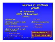
The pre-his<strong>to</strong>ry : generation of electric potential differences<br />
CAS - IC-2006<br />
1775 Volta’s electrophorus<br />
Wimhurst<br />
Machine<br />
circa 1880<br />
! few!tens!KV<br />
B. Le Roy<br />
type<br />
machine<br />
II half 18th<br />
century<br />
Winter<br />
machine<br />
mid 19th<br />
century<br />
2
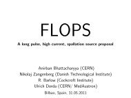
1897<br />
CAS - IC-2006<br />
Utilization of voltage genera<strong>to</strong>rs Discoveries<br />
3
1845-1923<br />
1850-1918<br />
CAS - IC-2006<br />
Utilization of voltage genera<strong>to</strong>rs Discoveries<br />
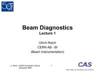
1879 W. Crookes : Discharges in gas:<br />
1895 W.C. Röntgen discovers X-ray production in discharge<br />
tubes when sufficiently high voltage is applied.<br />
1896 A.H. Bequerel discovers radioactivity (of U), further studied<br />
by Pierre and Marie Curie .<br />
1897 F. Braun builds cathodic ray tube<br />
1897 J.J. Thompson measures the ratio q/m of cathodic rays : they are electrons<br />
1900 E. Rutherford finds there are different<br />
species of radioactive products :<br />
α : He nuclei<br />
β : electrons<br />
γ : neutral (e.m.) radiation<br />
4
CAS - IC-2006<br />
1904 What do we know.......<br />
First we must ask what is positive electricity and the answer is still we do not know ..……..<br />
But concerning negative electricity we know a great deal more.<br />
This exists in excessively minute particles, sometimes called electrons and sometimes called<br />
corpuscles: these are thrown off the negatively charged terminal in a vacuum tube, and they fly<br />
with tremendous speed till they strike something. When they strike they can propel as well as<br />
heat the target, and they can likewise make it emit a phosphorescent glow: especially if it be<br />
made of glass or precious s<strong>to</strong>nes. If the target is a very massive metal like platinum, the sudden<br />
s<strong>to</strong>ppage of the flying electrons which encounter it causes the production of the ethereal pulses<br />
known as X-rays. Electrons are not very easy <strong>to</strong> s<strong>to</strong>p however; and a fair proportion of them<br />
can penetrate not only wood and paper, but sheets of such metals as aluminum, and other<br />
moderately thin obstacles. That is because they are extremely small, much smaller than the<br />
a<strong>to</strong>ms of matter.<br />
If a magnet be brought near a stream of flying electrons they are deflected by the magnetic<br />
force, as a rifle bullet is deflected by a wind; they will then miss the target at which they were<br />
aimed, and nay strike another. By measuring their deflection when their speed is known it is<br />
possible <strong>to</strong> estimate the mass of each particle; and if any stream consisted of particles of<br />
different masses it would be possible thus <strong>to</strong> sort or fan or winnow them out: the massive ones<br />
keeping nearly straight and the lighter ones being blown aside, somewhat as a cork projectile is<br />
more easily deflected than a bullet.<br />
Determinations made in this sort of way, supplemented by many other refined and most<br />
ingenious measurements conducted in the Cavendish Labora<strong>to</strong>ry, Cambridge, England, have<br />
resulted in the following knowledge:.........<br />
O.Lodge, Harper Magazine 1904, http://www.oneillselectronicmuseum.com/index.html<br />
5
CAS - IC-2006<br />
X-ray tubes<br />
Villard Tube (1898-1905)<br />
http://www.orau.org/ptp/collection/xraytubes/x-raytubes.htm<br />
6
CAS - IC-2006<br />
Principle of electrostatic accelera<strong>to</strong>rs<br />
The simplest method <strong>to</strong> accelerate charged particles ::<br />
Charged particles produced by a source (elettroni from a hot filament, pro<strong>to</strong>ns produced by<br />
stripping H a<strong>to</strong>ms, ....) are accelerated across a static potential difference ΔV<br />
The particle kinetic energy gain is<br />
Because<br />
!<br />
rot r E = 0<br />
Highest possible energy gain<br />
F<br />
Vo V<br />
ΔT= q ΔV<br />
one pass only<br />
"<br />
r<br />
E !d r s<br />
= 0<br />
Highest possible ΔV<br />
8
CAS - IC-2006<br />
A curious example:<br />
First, impulsive, high voltages<br />
1928-1930 - C. Urban, A.Brasch and F.Lange, experimenting in the italian Alps,<br />
succeeded in using potential differences between s<strong>to</strong>rm clouds and ground <strong>to</strong> produce<br />
huge voltage drops between two suspended spheres:<br />
Brash and Lange’s lightning catcher. E and H are the spheres between which<br />
the discharge occurs; AE, the antenna; a,a, insula<strong>to</strong>rs; b,b, conduc<strong>to</strong>rs; d, a<br />
grounded wire. A.Brash and F.Lange, Zs. F. Phys.,70 (1931), 17<br />
The experiments were dangerous: in their course C. Urban was killed by lightning<br />
9
About physics needs and electrostatic accelera<strong>to</strong>r technology<br />
Energy is crucial but not the only requirement….<br />
1930 E. Rutherford farsightedly says :<br />
“What we require is an apparatus <strong>to</strong> give us a potential of the order of 10<br />
million volts which can be safely accomodated in a reasonably sized room<br />
and operated at a few kilowatts of power.<br />
We require <strong>to</strong>o an exausted (evacuated) tube capable of withstanding this<br />
voltage…….I see no reason why such requirements can not be made<br />
practical.”<br />
http://content.cdlib.org/xtf/view?docld=ft5s200764&chunk.id=d0e2505&<strong>to</strong>c.depth=1&<strong>to</strong>c.id=d0e2505&brand=ucpress<br />
CAS - IC-2006<br />
A modern ~10 MV<br />
“exausted tube”<br />
alias “accelerating<br />
column”<br />
10
Accelerating column<br />
CAS - IC-2006<br />
Next Brash and Lange impulsive apparatus<br />
Spark-gap like<br />
Transformer<br />
Voltage from the transformer multiplied by the string of capaci<strong>to</strong>rs discharges<br />
across evacuated laminated tube. Zs. F. Phys.,70 (1931), 30<br />
http://content.cdlib.org/xtf/view?docld=ft5s200764&chunk.id=d0e2505&<strong>to</strong>c.depth=1&<strong>to</strong>c.id=d0e2505&brand=ucpress<br />
11
CAS - IC-2006<br />
Definition of a particle accelera<strong>to</strong>r<br />
A device that accelerates particles producing a beam that has controllable<br />
- Intensity (number of particles /unit time)<br />
- Energy<br />
- Energy spread<br />
- Transverse (with respect <strong>to</strong> its velocity) size<br />
- Angular spread<br />
The beam intensity may also be modulated in time in a controllable<br />
way.<br />
One can say that, like for light beams, beam quality (brightness) is<br />
proportional <strong>to</strong> the ratio :<br />
Brightness !<br />
Intensity<br />
Transverse size" Angular spread"Energy spread<br />
12
CAS - IC-2006<br />
The first “high energy” accelera<strong>to</strong>r<br />
Using this device <strong>to</strong> accelerate pro<strong>to</strong>ns produced by a discharge in H gas ,<br />
G. Cockroft and E. Wal<strong>to</strong>n obtained the first nuclear transmutation via the reaction :<br />
This earned them the Nobel Prize.<br />
3 Li 7 + 1 H 1 (p) = 2 2 He 4 (2 α)<br />
1932<br />
400<br />
KV<br />
This type of<br />
accelera<strong>to</strong>r<br />
takes its name<br />
from that of<br />
both its<br />
inven<strong>to</strong>rs<br />
13
V<br />
Cockroft & Wal<strong>to</strong>n voltage multiplier<br />
VN = 2 N Vo - #$ !i" / (12 foC )<br />
!<br />
Supplies a DC voltage.<br />
Main limitation is V ripple<br />
!V N =<br />
8 V ÷ 6 V<br />
C7<br />
6 V ÷ 4 V<br />
C 5<br />
4 V ÷ 2 V<br />
C3<br />
2 V ÷ 0<br />
C1<br />
(1 2) N (N +1)"i#<br />
Cf<br />
CAS - IC-2006<br />
± V<br />
Tr<br />
Terminale AT<br />
HV Terminal<br />
D 2<br />
D 2<br />
D 2<br />
D 2<br />
D 1<br />
D 1<br />
D 1<br />
D 1<br />
8V<br />
6V<br />
4V<br />
C8<br />
C6<br />
C4<br />
2V<br />
C2<br />
% & ' 8N 3 + 9 N 2 #$ + N % &<br />
E. Fermi - E. Amaldi first C&W<br />
ISS, Roma, 1936-1946<br />
Now an exibit in Frascati<br />
C&W machine at LBL<br />
C&W accelera<strong>to</strong>rs are still in use<br />
as pre-injec<strong>to</strong>rs in<strong>to</strong> larger ion<br />
accelera<strong>to</strong>rs but are rapidly being<br />
replaced by smaller, e.m. type<br />
machines (RF quadrupoles)<br />
14
CAS - IC-2006<br />
Technology drive<br />
Further improvement on e.s. devices<br />
voltage are essentially driven by<br />
technology of :<br />
- charging system<br />
and<br />
- insulation<br />
The<br />
Van de Graaff<br />
accelera<strong>to</strong>r<br />
15
@ M.I.T.<br />
Air-insulated<br />
High voltage problems !<br />
Beam pipe<br />
A pro<strong>to</strong>type<br />
CAS - IC-2006<br />
A new idea: the first Van-de-Graaff accelera<strong>to</strong>rs 1931<br />
5 MV<br />
Full scale accelera<strong>to</strong>r<br />
Source Labora<strong>to</strong>ry<br />
R. J. Van de Graaff<br />
www.mos.org/sln/<strong>to</strong>e/his<strong>to</strong>ry.html<br />
+ -<br />
V (max)<br />
(MV ) ! 3 " R(m)<br />
16
CAS - IC-2006<br />
VdG charging scheme A non conducting conveyor belt picks up<br />
charge at the low end, by corona discharge<br />
from a sharp pointed “comb” facing it and<br />
connected <strong>to</strong> a dc power supply.<br />
The belt penetrates inside a metal sphere,<br />
where there is no electric field, and discharges<br />
through a second comb connected <strong>to</strong> the<br />
inside surface of the sphere.<br />
Of course the belt mo<strong>to</strong>r has <strong>to</strong> provide the<br />
work <strong>to</strong> bring enough charge per unit time <strong>to</strong><br />
the <strong>to</strong>p, <strong>to</strong> compensate the extracted desired<br />
beam current, plus all other current losses.<br />
Van de Graaff’s<br />
improved scheme<br />
content.cdlib.org/xtf/view?docld=ft5s200764&chunk.id=d0e2505&<strong>to</strong>c.depth=1&<strong>to</strong>c.id=d0e2505&brand=ucpress<br />
17
CAS - IC-2006<br />
Van de Graaff: ultimate voltage limit<br />
Accelerated current<br />
Corona effects<br />
Resistive current<br />
Total current<br />
The ultimate voltage, for given radius of the terminal, is mainly determined by discharges,<br />
current losses, the power of the belt driving mo<strong>to</strong>r, the belt (subject <strong>to</strong> very large forces)<br />
mechanical resistance.<br />
In practice < ~ 25 MV<br />
18
CAS - IC-2006<br />
Paschen’s Law : !V disch = f (P "l)<br />
Across (infinite) parallel plates<br />
In air<br />
In SF6 @ 7 atm<br />
Belt charging system<br />
Higher voltage VdGs<br />
Pressurized<br />
!V disch " 30! W cm<br />
!V disch " 360!W cm<br />
!V disch = f (P "l )<br />
Pressure tank<br />
19
Van de Graaff charging sistems : belt, “pelletron”<br />
CAS - IC-2006<br />
Charging belts<br />
“combs”<br />
20
CAS - IC-2006<br />
Van de Graaff “Tandem Tandem” - A clever idea<br />
A variant of the VdG, a "Tandem" (TVdG) allows, by using a negative ion source, <strong>to</strong> utilise a same<br />
terminal potential difference twice over ( whence its name). In addition, by playing on the ion charge it<br />
can produce ions much higher final energies .<br />
Sorgente Source<br />
Negative Sorgente<br />
ion Ioni<br />
Source Negativi<br />
( n = -1)<br />
(n=-1)<br />
Terminale HV Terminal AT Stripper<br />
Stripper<br />
Tanca Pressure in pressione tank<br />
Accelerazione<br />
1st Acceleration Strip Accelerazione<br />
Acceleration<br />
!0 -> V<br />
per V -> 0<br />
( n = -1 )<br />
( + n )<br />
T ! 0 T = q V<br />
( + n )<br />
T = (1+n) qVo<br />
Negative ions with charge -e are first accelerated by the positive terminal voltage V <strong>to</strong> an<br />
energy eV. They are then passed through a stripper (thin foil, gas jet,..) that strips away<br />
n+1 of their electrons; the positively charged ions are then again accelerated <strong>to</strong> ground<br />
potential <strong>to</strong> an energy (n+1) eV.<br />
The stripper can be a thin foil of light material (e.g. C, Al, .. ) or, more frequently, a gas jet.<br />
The latter is preferred because foils are very delicate and must be frequently replaced.<br />
Stripping efficiency is a function of material and ion energy.<br />
E.G. : with a 15 MV terminal voltage, Au - ions can be stripped <strong>to</strong> a positive charge of up <strong>to</strong> q=13 e.<br />
Their final energy is therefore ~ (13+1)x15 MV ~200 MeV<br />
21
Tandem - Curve di stripping<br />
CAS - IC-2006<br />
IL valore di picco della carica dipende - per un da<strong>to</strong> stripper -<br />
dal tipo di ione e cresce rapidamente con l'energia dello ione.<br />
22
Tandems<br />
16 MeV<br />
Labora<strong>to</strong>ri Nazionali di Legnaro (Pd, It), 16 MV<br />
In operation.<br />
Both in Operation<br />
16 MV terminal Voltage<br />
Daresbury Labora<strong>to</strong>ry (UK), 20 MV<br />
Decommissioned<br />
CAS - IC-2006<br />
Labora<strong>to</strong>ri Nazionali del Sud (Ct, It), 16 MV<br />
In operation.<br />
23
Further acceleration :Tandem + cyclotron, a typical arrangement<br />
CAS - IC-2006<br />
v. LNS<br />
TANDEM<br />
CICLOTRONE<br />
CYCLOTRON<br />
II stripper<br />
Further ion energy increase through :<br />
- further acceleration<br />
- further charge increase<br />
N.B. : a tandem can provide very good, ~ 10 -4 , energy resolution (mainly due <strong>to</strong> voltage ripple<br />
at the terminal)<br />
24
G. Ising : the principle of electro-dynamic (multiple) acceleration<br />
Overcoming the limits of electrostatics by using non-conservative electric fields.<br />
G. Ising’s contribution in the words of Nobel Prize E.O. Lawrence:<br />
“ ….Profe ssor G. Ising , wh o in 1924 publi shed thi s impor tant principle .<br />
It was only after severa l year s ha d passed tha t I became a ware of Professo r<br />
Ising’s pri me contributi on.<br />
I shou l d li ke <strong>to</strong> take this opport unity <strong>to</strong> pay tribute <strong>to</strong> hi s wor k for he surely is<br />
the father of the devel opm ents of the metho ds of multiple a ccelera tion .“<br />
CAS - IC-2006<br />
Gustaf Ising, "Prinzip einer Methode zur<br />
Herstellung von Kanalstrahlen Hoher<br />
Voltzahl", Arkiv för Matematik,<br />
Astronomi och Fysik, Band 18 (1924)<br />
E.O. Law rence’s Nobel lecture<br />
25
1923<br />
At about the same time: R. Wideroe’s Wideroe s “ray ray transformer” transformer idea<br />
R. Wideroe invents the principle of the circular induction accelera<strong>to</strong>r<br />
nowadays called “Betatron” (but will not actually succeed in building a functioning one because<br />
“…the theory of stabilizing forces acting on the orbit had not yet been developed sufficiently.”<br />
CAS - IC-2006<br />
dB(R) 1<br />
=<br />
dt 2<br />
# 1<br />
$<br />
% R<br />
“The Infancy of Particle Accelera<strong>to</strong>rs”, DESY-Report 94-039.<br />
"<br />
0<br />
R<br />
&<br />
B(r)! dr<br />
'<br />
( = 1<br />
dB<br />
2 dt !<br />
B(R) = 1<br />
2 B<br />
26
1923<br />
CAS - IC-2006<br />
R. Wideroe’s Wideroe s “ray ray transformer” transformer idea<br />
R. Wideroe invents the principle of the circular induction accelera<strong>to</strong>r<br />
nowadays called “Betatron” (but will not actually succeed in building a functioning one because<br />
“…the theory of stabilizing forces acting on the orbit had not yet been developed sufficiently.”<br />
dB(R) 1<br />
=<br />
dt 2<br />
# 1<br />
$<br />
% R<br />
“The Infancy of Particle Accelera<strong>to</strong>rs”, DESY-Report 94-039.<br />
"<br />
0<br />
R<br />
&<br />
B(r)! dr<br />
'<br />
( = 1<br />
dB<br />
2 dt !<br />
B(R) = 1<br />
2 B<br />
27
1940<br />
Phys. Rev. 58, 841, 1940<br />
Kerst did develop the theory of<br />
beam focusing, essential <strong>to</strong> have<br />
a stable circulating beam.<br />
He studied and found the beam<br />
stability condition :<br />
dB B<br />
1 2 ! n " ! 1,!!!!!!<br />
dR R<br />
n : negative<br />
His accelera<strong>to</strong>r was industrialized<br />
for use as a X–ray source.<br />
CAS - IC-2006<br />
D.W. Kerst builds the first working betatron<br />
MAGNET<br />
Vacuum chamber<br />
Phys. Rev. 60, 47, 1941<br />
1944 : a first betatron is built in German industry; <strong>to</strong> its development collaborated B. Touschek<br />
B(R) = 1<br />
2 B<br />
28
CAS - IC-2006<br />
The Betatron is in practice usable only for electrons<br />
Using P max = q!R!B max<br />
(!" ) max<br />
E 0<br />
one obtains [1]<br />
c = qRB max !!!!!!#!!!!!!(!" ) max = q!c!R!B max<br />
E 0<br />
Given a maximum magnetic field, the maximum obtainable energy is inversely<br />
proportional <strong>to</strong> the accelerated particle mass.<br />
e. g. :<br />
Take a 0.7 m orbit radius betatron whose magnet reaches a 1 T maximum field and is<br />
powered by a 10 Hz sinusoid.<br />
- According <strong>to</strong> equation [1] when accelerating electrons, in the ultrarelativistic<br />
approximation cPmax ! Emax , one finds Emax = 210!MeV .<br />
For pro<strong>to</strong>ns, using a non relativistic approximation, one obtains<br />
T ! P2 c 2 (2E o ) = 23.5 MeV.<br />
One can also easily derive that the maximum accelerating electric field is<br />
E acc ! 44!!V /m only.<br />
A Cyclotron of same radius<br />
can do much better !<br />
29
CAS - IC-2006<br />
Wideroe : the birth of the “resonant resonant” accelera<strong>to</strong>rs class<br />
1927 Abandoning for the time the “ray transformer”, Wideroe invents and builds a<br />
small, 2 section resonant linear accelera<strong>to</strong>r with which he verifies the principle by<br />
accelerating ions <strong>to</strong> 50 KV using a 25 KV, 50 Hz genera<strong>to</strong>r.<br />
The patented drawing<br />
R.Wideroe’s sketch in: “The Infancy of Particle Accelera<strong>to</strong>rs”, DESY-Report 94-039.<br />
Alternate voltage genera<strong>to</strong>r<br />
@ frequency f<br />
Electric field regions<br />
RF OUT<br />
Drift Tube T5<br />
30
CAS - IC-2006<br />
Wideroe quotation on his linear, drift-tube accelera<strong>to</strong>r<br />
“As I speak about my life……… what always comes <strong>to</strong> my mind<br />
first is the Aachen drift-tube. Proving that it was possible <strong>to</strong><br />
accelerate electrically charged particles with alternating potentials<br />
and without having <strong>to</strong> use the restricted possibilities of the (at that<br />
time usual) d.c. voltage, appears <strong>to</strong> me as my most fundamental piece<br />
of work. This was the major result which I presented in my<br />
dissertation in 1927 and it does appear <strong>to</strong> have had the most farreaching<br />
consequences.”<br />
R.Wideroe in: “The Infancy of Particle Accelera<strong>to</strong>rs”, DESY-Report 94-039, 143, 1994.<br />
1
Following<br />
Ising<br />
&<br />
Wideroe<br />
CAS - IC-2006<br />
First high energy drift-tube linac<br />
PhysRev.38.2021 (1931)<br />
The Production of Heavy High Speed Ions without the Use of High Voltages<br />
D.H. Sloan and E.O.Lawrence<br />
A method has been developed for the multiple acceleration of ions <strong>to</strong> high<br />
speeds without the use of high voltages. The ions travel through a series of<br />
metal tubes in synchronism with an oscillating electric potential applied<br />
alternately <strong>to</strong> the tubes such that the electric field between tubes is always in a<br />
direction <strong>to</strong> accelerate the ions as they pass from the interior of one tube <strong>to</strong> the<br />
interior of the next. The ions are thereby successively accelerated <strong>to</strong> speeds<br />
corresponding <strong>to</strong> voltages as many times greater than the high frequency<br />
voltage applied <strong>to</strong> the tubes as there are tubes.<br />
In the present experiments a high frequency voltage of 42,000 volts at a wavelength<br />
of 30 meters applied <strong>to</strong> 30 such accelera<strong>to</strong>r tubes in line resulted in the<br />
production of a current of 10-7 amp. of 1,260,000 volt singly charged Hg ions.<br />
The surprising effectiveness of this experimental method for the generation of<br />
intense beams of high speed ions is due <strong>to</strong> the development of simple,<br />
convenient and effective methods for focusing and synchronizing the ions as<br />
they pass through the accelerating system.<br />
The present experiments show that ions having kinetic energies in excess of<br />
1,000,000 volt-electrons can be produced in this way with quite modest<br />
labora<strong>to</strong>ry equipment and with a convenience surpassing the direct utilization of<br />
high voltages, that the limit <strong>to</strong> the attainable ion speeds is determined mainly by<br />
the length of accelerating system and the size of the high frequency oscilla<strong>to</strong>r<br />
system, and consequently that the production of 10,000,000 volt ions is an<br />
entirely practicable matter.<br />
30 m 10 MHz<br />
©1931 The American Physical Society<br />
Received 19 Oc<strong>to</strong>ber 1931<br />
URL: http://link.aps.org/abstract/PR/v38/p2021<br />
2
CAS - IC-2006<br />
Wideroe’s Wideroe s linac limitations<br />
Given the frequency f RF of the driving oscilla<strong>to</strong>r, the length L i !!(i = 1, 2,...n) of the i!th<br />
drift tube, and v ! the velocity of the accelerated particle when entering it, a “resonance”<br />
i<br />
condition is established whenever<br />
Li = vi !!!!!!!!!Li = (" i c)/2 fRF 2 fRF in the sense that that the particle will always meet the same RF phase at every accelerating gap.<br />
The main limitation of the device stemmed from the RF technology of the time, based on<br />
lumped–constants drive circuits and therefore restricted <strong>to</strong> low (tens of KHz) frequencies:<br />
- at such low frequencies the drift-tubes lenghts become unmanageable unless<br />
RF<br />
E. g. :<br />
Ri<br />
Genera<strong>to</strong>re<br />
!!!!! f RF ! 10!!MHz!! 2L i ! 30 "# i !!m<br />
Cg1<br />
Cg2<br />
Cg3<br />
Cg4<br />
Cg5<br />
CS C1 C2 C3 C4 C5<br />
Drift tube Linac equivalent circuit<br />
Way out<br />
Increase the<br />
frequency<br />
!
Alvarez type drift-tube linac (19…) (19<br />
Drift-tubes are part of closed resonating structure.<br />
Such devices are still used <strong>to</strong> accelerate low<br />
energy pro<strong>to</strong>ns and ions.<br />
The resonant frequency is usually around a few<br />
hundred MHz, satisfying the condition<br />
CAS - IC-2006<br />
2L i(m) ! " i !!.<br />
In practice, their useful range is<br />
!
Cavity Resona<strong>to</strong>r<br />
The simplest schematization of a resona<strong>to</strong>r is thin gap<br />
across which an oscillating voltage<br />
CAS - IC-2006<br />
V(t) = V o sin(! RF t + ")<br />
(3.8.2)<br />
exists, f being an arbitrary phase constante and there<br />
being no special a-priori constraints on the oscillation sulla<br />
frequency RF .<br />
Whenever a charged particle crosses the gap its energy<br />
increases by<br />
!T (t) = qV o sin(" RF t + #)<br />
(3.8.3)<br />
5
E.O. Lawrence:<br />
1929 - 1932<br />
CAS - IC-2006<br />
the cyclotron<br />
Once the possibility of multiple acceleration was discovered, the idea of accelerating particles by<br />
passing them several times through a same accelerating “gap” rather than once through many<br />
different gaps came <strong>to</strong> the mind of several researchers in slightly different form. It was E.O. Lawrence,<br />
inspired by Wideroe’s “ray transformer”, that first presented, pursued and patented the scheme later<br />
named “cyclotron”.<br />
Lawrence’s<br />
patent<br />
claim<br />
design.<br />
T = 2! max 2 m f o 2 q 2<br />
R = max<br />
2 2 2<br />
R B max !!!<br />
2 mo N.B. : the vertical focusing effect of the gap<br />
electric field is first recognised<br />
The driving a.c. voltage genera<strong>to</strong>r, is connected across two cylindrical metallic half boxes separated by a<br />
gap and immersed in an axial magnetic field. Particles <strong>to</strong> be accelerated are introduced inside them, the<br />
boxes functioning as curved drift “tubes”, perform half circular orbits under the action of the magnetic<br />
field and, in a classic regime ( ! 1), experience the accelerating field every time they cross the gap in<br />
either direction.<br />
The latter, nature dictated, peculiarity is due <strong>to</strong> the time a particle takes <strong>to</strong> cover a half-orbit being<br />
independent from the particle energy and therefore from the orbit radius so that, provided it initially<br />
meets the field in a proper (accelerating) phase, it will stay in phase with it throughout.<br />
6
The first operating cyclotron and other LBL ones<br />
CAS - IC-2006<br />
1931 E.O. Lawrence and his graduate student M.S. Livings<strong>to</strong>n build the first<br />
successfully operating cyclotron. It accelerated a few hydrogen molecule ions <strong>to</strong> an<br />
energy of 80 KeV. “Each ion that reached full energy and fell in<strong>to</strong> a Faraday cup placed 4.5 cm<br />
from the center of the instrument had made no fewer than forty turns”.<br />
Result reported at the January 1931 APS meeting<br />
A series of other larger ones followed, at LBL, between 1935 and 1938<br />
E.O.Lawrence and his Labora<strong>to</strong>ry, www.lbl.gov/Science-Articles/Research-Review/Magazine/1981/<br />
60” diam<br />
220 <strong>to</strong>n magnet<br />
11 ft high<br />
8 MeV<br />
! 0.1÷ > 1!mA<br />
153 cm beam<br />
7
Lawrence’s Lawrence s 184” 184 Cyclotron<br />
CAS - IC-2006<br />
1940 Because of the war the machine was<br />
first completed in 1946.<br />
With an energy for D 2 of 200 MeV, it<br />
became the first over one hundred<br />
MeV accelera<strong>to</strong>r.<br />
Assembling the yoke of the ~<br />
4.7 m pole diameter magnet<br />
The machine was thus the first able <strong>to</strong><br />
produce, identify and precisely<br />
investigate mesons (1948).<br />
In 1950 it was upgraded <strong>to</strong> produce<br />
350 MEV pro<strong>to</strong>ns as well as 200 MeV<br />
deuterons and 400 MeV alpha<br />
particles.<br />
8
- Relativistic cyclotrons<br />
In view of reaching higher energies the classic cyclotron has two drawbacks :<br />
- the failure of isochronicity in the relativistic regime<br />
- the magnet diameter increasing, at constant B , like T max<br />
like T 3 2<br />
max ;<br />
CAS - IC-2006<br />
, the magnet volume and cost increase<br />
Modern cyclotrons still in use for basic science and medical applications incorporate one or both of the<br />
following techniques:<br />
- superconductivity, <strong>to</strong> obtain much higher magnetic fields for a given radius (SC cyclotrons)<br />
- shaping of the magnet poles <strong>to</strong> maintain isochronicity and focusing even in a moderately<br />
relativistic regime (sec<strong>to</strong>r-focussed cyclotrons, L.H. Thompson 1938).<br />
PSI (CH) Sec<strong>to</strong>r-yclotron for pro<strong>to</strong>ns, normal conducting<br />
590 MeV , average current up <strong>to</strong> 1.9 mA '.<br />
Pole of the Catania (It) SC sec<strong>to</strong>r cyclotron for heavy ions.<br />
B=5T, R=1m, Max energy for pro<strong>to</strong>ns : 600 MeV<br />
9
The Synchrotron<br />
1943 Cost of scaling a conventional cyclotron <strong>to</strong> higher energies and acceleration of relativistic<br />
particles (electrons) , were probably the <strong>to</strong>pics that prompted M. Oliphant, a british scientist then<br />
working on weapon-oriented research in the USA as E.O.Lawrence’s deputy, <strong>to</strong> come up with the<br />
concept of the “synchrotron”. He in fact writes, in a memo <strong>to</strong> the UK Direc<strong>to</strong>rate of A<strong>to</strong>mic Energy:<br />
“Particles should be constrained <strong>to</strong> move in a circle of constant radius thus enabling the use of an annular ring<br />
of magnetic field ... which would be varied in such a way that the radius of curvature remains constant as the<br />
particles gain energy through successive accelerations by an alternating electric field applied between coaxial<br />
hollow electrodes.”<br />
The problem of beam (longitudinal) stability in the presence of different trajec<strong>to</strong>ry lengths of particles<br />
starting with different initial conditions, in particular with finite initial energy spread, solved itself<br />
when V.I. Veksler and and E. McMillan, working on cyclotrons, independently formulated the “phase<br />
stability” principle (and applied it <strong>to</strong> “Synchrocyclotrons”).<br />
E. J. N. Wilson, “Fifty Years of Synchrotrons”, CAS; J.D. Lawson, “Early Synchrotrons In Britain and Early Work for Cern”, CAS<br />
CAS - IC-2006<br />
10
Synchrotron principle and a few formulae<br />
CAS - IC-2006<br />
δ<br />
f RF<br />
! p (t)!!Particle angular velocity<br />
q !VRF (t) = q" # E(t) Energy supplied per turn<br />
E(t) =!Eoe i[! RF (t )"t+# o ] !Average electric field in the gap<br />
The final energy is then<br />
Calling the initial field phase ϕo and the orbit circumference L, the electric field seen by the particle<br />
can then be written :<br />
E n = E o e i (! o t " ! o nL<br />
#c +$ o )<br />
T fin = Tin !+ " q !V<br />
n RF<br />
= Eo e i ! o t " nL<br />
&<br />
'<br />
#c<br />
%<br />
(<br />
)<br />
* +$ o )<br />
Note that this exspression has the same form as that of a wave travelling with velocity β c .<br />
!.<br />
δ cavity gap width<br />
(t n )<br />
Showing that in order for the sum <strong>to</strong> be non zero the particle must<br />
remain in phase with the Rf electric field. One must therefore have:<br />
! RF (t)!= k! p (t)<br />
Let us now take k=1 and also assume we are in the ultra-relativistic regime<br />
so that ω p = ω RF = constant.<br />
11
Weak focusing synchrotrons<br />
1951 start of construction<br />
CAS - IC-2006<br />
The BNL 3 GeV p-synchrotron<br />
“....even a few years later (after discovery of strong<br />
focusing principle) wise and experienced people<br />
decided <strong>to</strong> construct two large synchrotrons, Nimrod in<br />
the UK and the ZGS in the USA, based on the weak<br />
focusing scheme.<br />
It was believed that alternating-gradient machines, if<br />
they worked at all, would produce beam currents<br />
considerably smaller than the classical weak focusing<br />
ones, which had a much larger aperture.”<br />
G. Brianti, “The <strong>CERN</strong> Synchrotrons” CAS, <strong>CERN</strong>-97-04<br />
1953 start of design<br />
The 1 Gev Frascati e-synchrotron<br />
12
Weak and strong focusing<br />
CAS - IC-2006<br />
in the 1950’s 1950<br />
The early synchrotrons relied on focusing provided by magnetic field lines according <strong>to</strong> Kerst’s<br />
stability condition<br />
dB B<br />
1 2 ! n " ! 1,!!!!!! with!negative!!n<br />
dR R<br />
(negative sign field gradient)<br />
Kerst’ limits on n derive from the fact that a magnetic res<strong>to</strong>ring force component acts only in the<br />
vertical plane while in the radial plane the force component has the the wrong direction and is<br />
over–compensated by the effect of the particle orbit curvature only provided the field gradient<br />
( R B)!<br />
( dB dR)!!!!!!<br />
stays inside the above limits.<br />
The resulting focusing is “weak” which entails relatively large beam sizes, large pole widths and<br />
therefore a costly magnet in addition <strong>to</strong> expected stability problems at energies exceeding ~ 10 GeV.<br />
This picture was changed dramatically at around 1952 when E. Courant, M. Livings<strong>to</strong>n and<br />
H. Snyder, at Brookhaven, proposed strong focusing, or alternating-gradient (AG) magnetic<br />
lattices consisting of bending magnets with alternating sign of the gradient or of properly<br />
spaced quadrupole magnets with opposite polarities, which solved the above problems<br />
allowing for much higher energies per given price.<br />
Why : given two lenses with focus and separated by a distance d , their combination<br />
f1 ! ! f2 !<br />
has<br />
1<br />
f<br />
= 1<br />
f 1<br />
+ 1<br />
f 2<br />
! d<br />
f 1 f 2<br />
always positive if<br />
f 1 != ! f 2<br />
(and in a range around it),<br />
else: the beam defocused by one lens arrives at the following (focusing ) lens further from the axis and<br />
is therefore focused more strongly.<br />
All modern synchrotrons are strong-focused<br />
P.J. Bryant, A brief his<strong>to</strong>ry and review of accelera<strong>to</strong>rs, CAS ; E. J. N. Wilson, “Fifty Years of Synchrotrons”, CAS<br />
13
Weak focusing synchrotrons<br />
CAS - IC-2006<br />
- Cosmotron<br />
The Cosmotron vacuum chamber<br />
14
Synchrotron progress in time<br />
CAS - IC-2006<br />
15
Back <strong>to</strong> linacs in the ultra-relativistic regime (mainly electron linacs) linacs<br />
Take a sequence of identical equally-spaced cavities centered on a straight trajec<strong>to</strong>ry, spaced by L.<br />
It can easily be seen that the argument made in the previous slide still holds so that the condition for the<br />
particle <strong>to</strong> be continuously accelerated is<br />
CAS - IC-2006<br />
E n = E o e i (! o t " ! o nL<br />
#c +$ o )<br />
= Eo e i ! o t " nL<br />
&<br />
'<br />
#c<br />
%<br />
(<br />
)<br />
* +$ o )<br />
If therefore one can produce a wave travelling trough the<br />
structure here schematised a particle injected will be accelerated<br />
throughout <strong>to</strong> a final energy one can write as<br />
T fin = T in !+q E o e i ! acc<br />
L nL<br />
With the development of high frequency ( in the GHz,<br />
S-band region or higher) power electronics, mainly<br />
developed during the II world war for radar applications, closed structures (waveguides) can be built and<br />
powered that can carry waves travelling at speeds<br />
less than c . They are used in all “warm” e-Linacs.<br />
!.<br />
16
CAS - IC-2006<br />
Short His<strong>to</strong>ry of Particle Accelera<strong>to</strong>rs<br />
S<strong>to</strong>rage Ring and Linear Colliders<br />
Scaletta : Primissime macchine es<br />
interesse per la Fisica<br />
Principio macchine es<br />
Problema della tensione<br />
Primo C&W<br />
S<strong>to</strong>rage rings- Colliders<br />
17
Colliding beams<br />
1943 R. Wideroe again.. “…I had thus come upon a simple method for improving the exploitation of particle<br />
energies available .. for nuclear reactions. As with cars (collisions), when a target particle (at rest) is<br />
bombarded, a considerable portion of the kinetic energy (of the incident particle) is used <strong>to</strong> hurl it (or the<br />
reaction products) away.<br />
Only a relatively small portion of the accelerated particle’s energy is used <strong>to</strong> actually <strong>to</strong> split or destroy the<br />
colliding particles. However, when the collision is frontal, most of the available kinetic energy can be exploited.<br />
For nuclear particles, relativistic mechanics must be applied, and .. the effect .. be even greater “.<br />
In fact, relativistically, for a same amount of energy available in the center of mass system, the<br />
energy of the incident particle in a fixed target experiment , ! F , and that of each of two particles<br />
in head-on collision , ! , obey the equation:<br />
C<br />
In addition :<br />
“… If it were possible <strong>to</strong> s<strong>to</strong>re the particles in rings for longer periods, and if these ‘s<strong>to</strong>red’ particles<br />
were made <strong>to</strong> run in opposite directions, the result would be one opportunity for collision at each<br />
revolution.<br />
Because the accelerated particles would move very quickly they would make many thousand<br />
revolutions per second and one could expect <strong>to</strong> obtain a collision rate that would be sufficient for many<br />
interesting experiments.”<br />
CAS - IC-2006<br />
2<br />
! F = 2! C<br />
18
The s<strong>to</strong>rage ring-collider concept<br />
D.W. Kerst et al “The possibility of producing interactions in stationary coordinates by directing beams<br />
CAS - IC-2006<br />
against each other has often been considered, but the intensities of beams so far available have<br />
made the idea impractical.<br />
…………… accelera<strong>to</strong>rs offer the possibility of obtaining sufficiently intense beams so that it<br />
may now be reasonable <strong>to</strong> reconsider directing two beams of approximately equal energy at<br />
each other.”<br />
D. W. Kerst et al., Phys. Rev. 102, 590 (1956).<br />
G. K. O’Neill, interested in p-p collisions,<br />
introduces the idea of injecting the beam extracted<br />
from a high energy pro<strong>to</strong>n synchrotron in two<br />
“s<strong>to</strong>rage rings” in which particles would be<br />
accumulated and s<strong>to</strong>red for a long time. Typically<br />
in a figure-of-8 configuration they have a common<br />
section in which the two s<strong>to</strong>red beams collide<br />
head-on.<br />
1956<br />
Collision straight section<br />
19
The s<strong>to</strong>rage rings concept<br />
1956<br />
CAS - IC-2006<br />
Some time later, G. K. O’Neill also observed:<br />
“The use of s<strong>to</strong>rage-rings on electron synchrotrons in the GeV range would allow the measurement of<br />
the electron-electron interaction at center-of-mass energies of about 100 times as great as are now<br />
available. The natural beam damping in such machines might make beam capture ( and<br />
accumulation ) somewhat easier than in the case of pro<strong>to</strong>ns.”<br />
Proc.<strong>CERN</strong> Symposium on H.E.Accelera<strong>to</strong>rs and Pion<br />
Physics , Geneva (1956), p. 36<br />
Bunches of particels coming from the injec<strong>to</strong>r are injected at some distance from the<br />
equilibrium orbit and start oscillating around it. Because electrons (but at the time<br />
not pro<strong>to</strong>ns) constrained on a curved path radiate energy away it can be shown that<br />
the amplitude of the oscillations is damped so that all injected particles end up in<br />
the vicinity of the equilibrium orbit. Injections can thus be frequently repeated<br />
without disturbing the s<strong>to</strong>red beam and adding the the newly injected particles <strong>to</strong> it<br />
Phase<br />
Space<br />
not<br />
conserved<br />
20
The first collider: collider:<br />
Prince<strong>to</strong>n-Stanford e-e experiment<br />
First s<strong>to</strong>red<br />
beam in<br />
1962.<br />
1957 G.K. O'Neill, B. Richter, W.C. Barber , B. Gittelman start building the e - e -<br />
Prince<strong>to</strong>n-Stanford colliding beam accelera<strong>to</strong>r, still weak focusing, 500 MeV per beam<br />
The group, (Richter in particular), became interested in performing e-e scattering<br />
experiments study the at that time much discussed problem of possible breakdowns of<br />
quantum electrodynamics at high energy. The proposed collider energy would reach a<br />
center of mass energy by far higher than that obtainable at other accelera<strong>to</strong>rs and could<br />
be a model for a future p-p collider.<br />
CAS - IC-2006<br />
First Stanford<br />
e - -e - collider<br />
From the<br />
HEPL MARK III<br />
1 GeV linac<br />
SLAC-PUB-6023, June 1992<br />
Technical problems solved:<br />
-the world’s largest ultra-high vacuum<br />
system (two cubic meters at 10 -9 <strong>to</strong>rr ).<br />
- injection kicker magnets faster than<br />
anything that existed at the<br />
time (80 ns pulse width, including a<br />
reasonable flat <strong>to</strong>p).<br />
- s<strong>to</strong>red beam currents in the 100’s of<br />
mA range.<br />
21
e+e- e+ e- physics and the birth of Anello nello di Accumulazione<br />
ccumulazione<br />
CAS - IC-2006<br />
B. Touschek , the lead theoretician in Frascati, did not believe in<br />
QED breakdowns but “...conceived electron-positron annihilation as the<br />
best <strong>to</strong>ol <strong>to</strong> transfer “pure” energy - that is without unwanted quantum<br />
numbers such as charge or <strong>to</strong>o large angular momentum or some other<br />
hadronic property - <strong>to</strong> the vacuum. “<br />
In 1960 he gave a seminar in Frascati presenting the main features of e + e - annihilation<br />
physics and proposing the construction of a small single ring injected from the 1.1 GeV<br />
Frascati electron synchrotron in which two bunches, one of electrons and the other of<br />
positrons, would circulate in opposite directions in a same vacuum chamber and collide<br />
once per turn.<br />
A week later, “. .given that preliminary studies have not shown insurmountable barriers......”, the<br />
machine was approved and named , funding made available, and construction started, <strong>to</strong> be<br />
completed one year later.<br />
Quotations from<br />
and BT’s beloved aunt !<br />
22
BT’s BT s seminar<br />
CAS - IC-2006<br />
C.Bernardini, Phys. Perspect. 6 (2004) 156–183<br />
23
B. Touschek’s notebook: birth of the first e + e - collider<br />
Archivio B. Touschek, Dip. di Fisica, Università “la Sapienza,”, Roma<br />
CAS - IC-2006<br />
The first page of Bruno Touschek’s notebook.<br />
The day before , during a meeting in in Frascati,<br />
he had proposed <strong>to</strong> build an accelera<strong>to</strong>r <strong>to</strong><br />
accelerate two particle beams and collide them<br />
head-on, <strong>to</strong> study the basic constituents of matter.<br />
The drawing shows a principle sketch of a ring<br />
collider.<br />
“State of affairs. Discussed plan with (G.) Ghigo.<br />
Decided for “...side”s<strong>to</strong>rage.<br />
G(higo) proposed use of γ -beam also for electrons.<br />
Typical possibility:<br />
AdA<br />
the ances<strong>to</strong>r of<br />
<strong>to</strong>day’s e+e- and<br />
pp bar colliders .<br />
Injection by gamma’s<br />
from the synchrotron<br />
producing pairs in<br />
internal thin targets<br />
1
Synchrotron<br />
CAS - IC-2006<br />
ADA in Frascati - the first e + -e- -e collider<br />
Nobody could tell which were positrons<br />
and which electrons !<br />
Beam loss<br />
due <strong>to</strong> falling<br />
dust<br />
2
CAS - IC-2006<br />
ADA first accumulation<br />
C.Bernardini, Phys. Perspect. 6 (2004) 156–183<br />
3
CAS - IC-2006<br />
ADA in Orsay<br />
But the synchrotron intensity was not high enough and<br />
following P. Marin’s proposal, AdA was transferred <strong>to</strong> Orsay.<br />
Injected by the 2 GeV Orsay electron/positron Linac<br />
C.Bernardini, Phys. Perspect. 6 (2004) 156–183<br />
J. Haissinski<br />
P. Marin<br />
4
The Touschek effect<br />
...at a certain point, we noticed that the injection rate was decreasing, and sometime later the s<strong>to</strong>red<br />
current increased no further – it had reached saturation.”<br />
A few hours later :<br />
“.....Bruno reappeared announcing: “I got it! It is Møller<br />
scattering in the bunch!”<br />
He then exhibited a formula, explaining that he had<br />
calculated that saturation should occur at the beam<br />
intensities we had reached because electron-electron<br />
scattering in the beam’s bunches was transferring<br />
energy from the betatron oscillations in the transverse<br />
directions in<strong>to</strong> the longitudinal stability zone, which was<br />
limited in the amount of energy it could accept.”<br />
CAS - IC-2006<br />
Steep energy dependence<br />
AdA achieved a peak luminosity of<br />
of 10 25 cm -2 s -1<br />
5
Adone design: choices and open questions<br />
1961 Study group under F. Amman<br />
1991 Decommissioned DAFNE<br />
Main open questions at the time of design:<br />
- Beam-beam limit<br />
- Positron production<br />
- Radiation effects in a strong focusing lattice<br />
- Ultra high vacuum in a large chamber and<br />
gas load from radiation desorption.<br />
CAS - IC-2006<br />
1963 First orders<br />
1968 First physics runs<br />
1.5 GeV beam energy,<br />
a nice round number but<br />
J/ψ a few tens of MeV higher !<br />
6
Adone design: early discoveries (= problems but learnig <strong>to</strong>o)<br />
Accelera<strong>to</strong>r physics and technology:<br />
- Head tail instability setting in at injection energy at the level of 100 µA circulating current<br />
- Strong longitudinal instabilities due <strong>to</strong> (hundreds of ) higher order modes in our four huge<br />
10 MHz cavities.<br />
- Single kick high voltage injec<strong>to</strong>r failures (eventually replaced ), ....<br />
CAS - IC-2006<br />
Other : Physics runs started in 1968 !<br />
Discovery of multi-hadron production, ......<br />
7
LEP (Large Electron Positron) - aerial view<br />
CAS - IC-2006<br />
8
LEP (Large Electron Positron)<br />
1981 approved, 1989 LEP 1 first collisions at 46 GeV/beam, at the Z 0<br />
LEP 2<br />
CAS - IC-2006<br />
1995 Upgraded operation starts with first installed of SC cavities<br />
2001 Decommissioned<br />
LEP Tunnel, 27 Km circumference<br />
“A number of technical challenges had <strong>to</strong> be met by innovative designs such as the following.<br />
- The cheap and rigid steel-concrete dipole magnets consisted of spaced iron laminations cement with<br />
mortar in between (27% steel filling), kept <strong>to</strong>gether by four pre-stressing rods running the whole<br />
length of 6 m. Concentration of the magnetic field in the laminations avoided reproducibility<br />
problems at injection where the average dipole field was only 240 G.<br />
- In order <strong>to</strong> avoid disturbance of the solenoid field in the detec<strong>to</strong>rs, warm-bore, iron-free<br />
superconducting low-beta quadrupoles had <strong>to</strong> be developed.”<br />
K.Hübner, 50 Years Of Research At Cern: From Past To Future. The Accelera<strong>to</strong>rs, <strong>CERN</strong>-AB-2005-031<br />
9
From ISR, the first p-p colliders, <strong>to</strong> the<br />
1965 : approved<br />
CAS - IC-2006<br />
<strong>CERN</strong> 1971 : in operation<br />
Spp bar S<br />
Two 31 GeV, ~940 m circumference rings<br />
intersecting in eight places.<br />
Pro<strong>to</strong>n bunches from the PS synchrotron were<br />
injected at 25 GeV, s<strong>to</strong>red next <strong>to</strong> each other using a<br />
“stacking in momentum space” technique first<br />
developed by Kerst’s group, accelerated <strong>to</strong> the final<br />
energy and de-bunched.<br />
The main challenge for the ISR was <strong>to</strong> accumulate<br />
high-enough currents and maintain small-enough<br />
beam dimensions <strong>to</strong> achieve the high luminosity<br />
required by physics.<br />
During actual physics runs it did s<strong>to</strong>re and collide<br />
world record currents, up <strong>to</strong> 57 A per beam, and<br />
luminosity of 1.4 10 32 cm -2 s -1 .<br />
The vacuum chamber pressure dictated by the<br />
desired beam lifetime also reached record values in the<br />
range of 10 -11 <strong>to</strong>rr.<br />
The ISR, first of its kind, was quite obviously<br />
faced with many unexpected problems (resistive<br />
wall insatability, pressure bumps…) whose solution<br />
contributed significantly <strong>to</strong> the advancement of the<br />
field.<br />
Most significantly, S. Van der Meer i nvented for the IS R “s<strong>to</strong>chastic cooling”, a terchnique that<br />
senses s<strong>to</strong>chastic density fluctuations in the beam and damps them out by an active feedback system,<br />
which earned him the Nobel Prize shared with C. Rubbia.<br />
Developed for and applied <strong>to</strong> the accelera<strong>to</strong>r <strong>to</strong> improve its performance, it was the key <strong>to</strong> the<br />
realization of the SppS pro<strong>to</strong>-antipro<strong>to</strong>n collider completed in 1981 .<br />
10
The first e-p collider : HERA at DESY<br />
19.. : approved 19.. : in operation<br />
CAS - IC-2006<br />
11
CAS - IC-2006<br />
2007<br />
C.Bernardini, Phys. Perspect. 6 (2004) 156–183<br />
ADA <strong>to</strong> LHC<br />
II<br />
12
CAS - IC-2006<br />
2007<br />
C.Bernardini, Phys. Perspect. 6 (2004) 156–183<br />
ADA <strong>to</strong> LHC<br />
ILC<br />
I<br />
13<br />
ILC 2
7 TeV c.m.<br />
CAS - IC-2006<br />
LHC - pp<br />
14
The Future of Colliders<br />
“On the pro<strong>to</strong>n line, one has gone from the first bold initiative, the ISR at <strong>CERN</strong> which used<br />
conventional magnets, <strong>to</strong> the superconducting magnets that are used in all of the pro<strong>to</strong>n colliders built<br />
<strong>to</strong>day.”<br />
“On the electron line, one can see a kind of complete cycle in accelera<strong>to</strong>r technology, from the birth of the<br />
colliding-beam s<strong>to</strong>rage ring <strong>to</strong> its culmination in LEP II and the beginning of the<br />
next technique for high-energy electron collisions,<br />
the linear collider.”<br />
(B.Richter, The rise of colliding beams, SLAC-PUB-6023, 1992 ).<br />
CAS - IC-2006<br />
The case of electron colliders<br />
- Using B. Richters semi-empiric e+e- collider cost-optimization law:<br />
because :<br />
R !E B one has<br />
B !!E R!!!!1 E 1st<br />
For any fixed radius, the average power radiated-away per turn, is :<br />
P !E4 R<br />
P<br />
E !E3<br />
! " R #E2<br />
Problem<br />
2nd Problem<br />
In practice : a circular collider <strong>to</strong> gain a fac<strong>to</strong>r of the order of 10 in energy w.r. <strong>to</strong> LEP<br />
can not be envisaged.<br />
P<br />
15
The first “linear linear” collider : SLC<br />
CAS - IC-2006<br />
(SLAC Linear Collider) Collider<br />
1983 Start construction 1987 start commissioning 1990 start experiments<br />
50 GeV cm energy<br />
Courtesy of C. Pagani<br />
16
ILC<br />
2015 ?<br />
CAS - IC-2006<br />
CLIC<br />
Warm Linacs approach NLC , SLAC-KEK Collaboration<br />
@ <strong>CERN</strong><br />
CLIC<br />
3 TeV c.m.<br />
f RF = 30 GHz V acc ~ 100 MV/m<br />
CLIC Test Facility<br />
Superconducting Linacs approach<br />
TESLA Collaboration<br />
(over 40 Institutions)<br />
1990<br />
2005<br />
~2015<br />
TTF test Facility<br />
Decision: choice of SC technology<br />
International Linear Collider<br />
Worldwide collaboration<br />
500 GeV c.m. 1TeV<br />
f RF =1.5 GHz V acc = 35 MV/m<br />
17
Drive bunch excited plasma wake acclera<strong>to</strong>r<br />
CAS - IC-2006<br />
18
CAS - IC-2006<br />
A NEW GENERATION : Laser-Plasma acceleration<br />
ILC<br />
LWF :Laser Wake Field<br />
19
Laser-Plasma acceleration : early work<br />
1983<br />
Started in the early 1960’s with the work of J.M. Dawson<br />
“Recently there has been a great deal of interest in using laser-plasma interactions <strong>to</strong> accelerate particles <strong>to</strong><br />
high energies more rapidly than the 20 MeV/m <strong>to</strong> which linear accelera<strong>to</strong>rs are currently limited.”<br />
“The beat-wave accelera<strong>to</strong>r is one scheme proposed by Dawson and Tajima <strong>to</strong> excite large amplitude<br />
electrostatic plasma waves which can accelerate particles.”<br />
but<br />
“…… particles in the beat-wave accelera<strong>to</strong>r can gain only a finite amount of energy before they become out of<br />
phase with the beat wave….”<br />
“The limitation on the <strong>to</strong>tal energy gain … with recent plasma accelera<strong>to</strong>r schemes such as the beat-wave<br />
accelera<strong>to</strong>r ….. is overcome by the Surfatron.<br />
By introducing a perpendicular magnetic field it is possible <strong>to</strong> keep particles in phase with the laser-induced<br />
plasma waves and hence accelerate them <strong>to</strong> arbitrarily high energy.<br />
The particles may be accelerated <strong>to</strong> arbitrarily high energy as they ride across the wave fronts like surfers<br />
cutting across the face of an ocean wave…”<br />
T. Katsouleas and J. M. Dawson, “A Plasma Wave Accelera<strong>to</strong>r - Surfatron 1”, IEEE Trans. Nucl. Science, Vol. NS-30, No. 4, August 1983<br />
CAS - IC-2006<br />
20
Laser excited plasma wake<br />
For laser light of TYPICAL INTENSITY,<br />
striking the plasma, the light’s electric field<br />
(red wave) makes plasma electrons oscillate<br />
at relatively low speeds so that the light’s<br />
magnetic field (blue wave) does not<br />
appreciably affect them.<br />
At MUCH HIGHER INTENSITIES the light<br />
striking the plasma makes the plasma<br />
electrons oscillate at velocities close <strong>to</strong> c do<br />
that the light’s magnetic field makes them fly<br />
forward at high speed leaving the heavier<br />
positive ions behind.<br />
This produces very high electric fields in<br />
between the now separated charges (red<br />
arrows).<br />
The gap between charges and the associated<br />
electric field trails along in the light wake<br />
and can accelerate other charged particles <strong>to</strong><br />
very high energy<br />
CAS - IC-2006<br />
21
Channeled electron beam<br />
Laser propaga without and with plasma channel<br />
CAS - IC-2006<br />
22
Progress in Laser acceleration<br />
CAS - IC-2006<br />
V. Malka et al , “Optically Induced GeV Electron Beams: The LOA Strategy ”, (2006),<br />
quasi<br />
23
Conclusions<br />
V. Malka et al , “Optically Induced GeV Electron Beams: The LOA Strategy”, (2006),<br />
CAS - IC-2006<br />
24