horizontal plastic injection molding machine - Irsst
horizontal plastic injection molding machine - Irsst
horizontal plastic injection molding machine - Irsst

Create successful ePaper yourself
Turn your PDF publications into a flip-book with our unique Google optimized e-Paper software.
HORIZONTAL PLASTIC INJECTION MOLDING MACHINE<br />
SAFETY<br />
CHECKLISTS<br />
RG-687
SAFETY<br />
CHECKLISTS<br />
This document has been developed to support companies in the <strong>plastic</strong>s processing industry in their<br />
efforts to prevent accidents involving <strong>horizontal</strong> <strong>plastic</strong> <strong>injection</strong> <strong>molding</strong> <strong>machine</strong>s. It can also serve as<br />
a basic document in the training offered to the personnel in these companies and to students in <strong>plastic</strong>s<br />
processing. However, it does not allow a risk analysis to be done to determine the limits, to identify<br />
hazards, and to estimate the risk; in these cases, appropriate standards must be consulted. Users of this<br />
document must have knowledge about <strong>horizontal</strong> <strong>plastic</strong> <strong>injection</strong> <strong>molding</strong> <strong>machine</strong>s in general, and<br />
the ones that they use in particular.<br />
Practical safety checklists make up the core of this document, namely a general checklist on the<br />
safeguarding of <strong>machine</strong>s, and a specific checklist for those individuals who perform various tasks on<br />
these <strong>machine</strong>s, such as production, tuning, maintenance. These checklists essentially refer to sections<br />
of ANSI/SPI B151.1 – 2007 standard (see reference 1), which are indicated for consultation purposes.<br />
The components of a <strong>horizontal</strong> <strong>plastic</strong> <strong>injection</strong> <strong>molding</strong> <strong>machine</strong> and the safeguards against its<br />
inherent risks are also presented to facilitate the use of the checklists.<br />
These risks can lead to serious, and even fatal, injuries. The following tables present the main harm<br />
that can be associated with the hazard zones of the mold closing unit and <strong>injection</strong> unit of<br />
these <strong>machine</strong>s.<br />
MOLD AREA<br />
(mold opening and closing<br />
movements, movement<br />
of ejectors)<br />
CLOSING MECHANISM<br />
(shearing and pinch points<br />
on the sides and behind<br />
the movable platen)<br />
MOLD CLOSING UNIT<br />
HAZARD ZONES POSSIBLE HARM<br />
• Burns<br />
• Injury due to expelled material<br />
(e.g., fragments from an improperly<br />
installed mold)<br />
• Shearing<br />
• Impact<br />
• Crushing<br />
• Death<br />
• Shearing<br />
• Impact<br />
• Crushing<br />
To download this document: www.irsst.qc.ca/media/documents/PubIRSST/RG-687.pdf<br />
NOZZLE AREA<br />
SCREW AREA<br />
(screw, feed throat leading to<br />
an access to the screw, vent on<br />
the <strong>plastic</strong>izing unit,<br />
<strong>injection</strong> barrel)<br />
INJECTION UNIT<br />
HAZARD ZONES POSSIBLE HARM<br />
• Burns<br />
• Injury due to expelled material<br />
• Intoxication by the vapours emitted<br />
from the hot <strong>plastic</strong><br />
• Crushing<br />
• Shearing<br />
• Burns<br />
• Intoxication by the vapours emitted<br />
from the hot <strong>plastic</strong><br />
• Winding around the screw<br />
• Shearing<br />
• Crushing<br />
• Death<br />
2
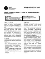
FIGURE 1<br />
HORIZONTAL PLASTIC INJECTION MOLDING MACHINE: COMPONENTS<br />
1. Backing platen<br />
2. Closing mechanism - Toggle lever and cylinder<br />
3. Ejector<br />
4. Movable platen (Floating platen)<br />
5. Tie bar<br />
6. Fixed platen<br />
7. Nozzle<br />
8. Barrel head<br />
9. Heater band<br />
10. Injection barrel (Transfer chamber)<br />
11. Screw<br />
12. Feed hopper<br />
13. Feed throat<br />
14. Screw motor<br />
15. Parts discharge opening<br />
16. Mold<br />
17. Digital control panel<br />
18. Frame<br />
1 2 3 4 5 6 7 8 9 10 11 12 13 14<br />
To download this document: www.irsst.qc.ca/media/documents/PubIRSST/RG-687.pdf<br />
15 16 17 18<br />
DRAWING: CHRISTIAN SIRARD T.P.<br />
3
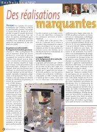
FIGURE 2<br />
SAFEGUARDS: GUARDS<br />
1. Guard at the end of the closing mechanism (section A-A)<br />
2. Guard for the closing mechanism<br />
3. Mold area guard (operator side)<br />
4. Guard opposite the operator side<br />
5. Top guard<br />
6. Guard at the end of mold area (section B-B)<br />
7. Purge splash guard<br />
8. Injection barrel guard<br />
9. Feed throat casing<br />
10. Screw coupling guard<br />
11. Guard under the closing mechanism<br />
12. Guard (or conveyor or chute) for the parts discharge opening<br />
TOP VIEW<br />
1 2 3<br />
6<br />
A 7 B 8 9 10<br />
A<br />
11 12<br />
To download this document: www.irsst.qc.ca/media/documents/PubIRSST/RG-687.pdf<br />
4 5<br />
B<br />
NOTE: Guard 4 is installed<br />
on the <strong>machine</strong>, opposite<br />
guard 3, and may<br />
resemble it.<br />
SECTION A-A SECTION B-B<br />
DRAWING: CHRISTIAN SIRARD T.P.<br />
4
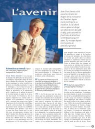
FIGURE 3<br />
PROTECTIVE DEVICES<br />
EXAMPLE OF BLOCKING MECHANISM FOR THE MOVABLE PLATEN WHEN THE MOLD<br />
AREA GUARD (OPERATOR SIDE) IS OPEN<br />
Different protective devices are installed on guards such as the<br />
mold area guard. Their state allows the relevant parts of the<br />
<strong>machine</strong> to operate or not. Position switches and hydraulic or<br />
pneumatic valves are examples of protective devices<br />
(see reference 2 to learn about their safe installation).<br />
In the mold area, the blocking mechanism for the movable<br />
platen is also a protective device, as illustrated below.<br />
1 2<br />
7 6<br />
To download this document: www.irsst.qc.ca/media/documents/PubIRSST/RG-687.pdf<br />
A<br />
A<br />
1. Cam connected to the guard<br />
2. Cone rod attached to the mobile mold<br />
3. Locking device pivot<br />
4. Lowered locking device (open guard)<br />
5. Cone rod<br />
6. Stationary part of mold<br />
7. Mobile part of mold<br />
By means of its cam, the guard allows<br />
the locking device to drop as it opens,<br />
and raises it as it closes.<br />
3<br />
Section A–A magnified<br />
Guard closed and locking device raised<br />
Mechanical device to block the closing of the mold by means of a cone rod<br />
and a locking device falling by gravity between the cones and stopping the<br />
forward motion of the movable platen when the guard is open. Closing of<br />
the guard raises the locking device and allows the mold to close.<br />
NOTE: There are also mechanical blocking devices that are the opposite of<br />
this illustration: the cone rod is installed on the stationary part of the mold,<br />
with the locking device falling on the mobile part.<br />
4<br />
5<br />
5
ACCESS TO<br />
THE MOLD<br />
FROM THE<br />
OPERATOR<br />
SIDE<br />
CHECKLISTS<br />
N°<br />
1.<br />
2.<br />
3.<br />
4.<br />
5.<br />
6.<br />
7.<br />
Checklist completed by:<br />
Signature:<br />
Date (MM/DD/YYYY):<br />
SAFEGUARD CHECKLIST<br />
Each <strong>machine</strong> must be subjected to verifications using the following checklists.<br />
“Yes” answers to the statements on the checklists are synonymous with compliance with<br />
the standard. “No” answers imply that the <strong>machine</strong> must be repaired or stopped.<br />
The general checklist for verifying the safeguarding of the <strong>horizontal</strong> <strong>injection</strong> <strong>molding</strong> <strong>machine</strong> is intended primarily for<br />
the person in charge of start-up of the <strong>machine</strong>.<br />
Horizontal <strong>plastic</strong> <strong>injection</strong> <strong>molding</strong> <strong>machine</strong>:<br />
(identification number or make, model and year of manufacture)<br />
Submitted to:<br />
SAFEGUARDING OF THE MOLD CLOSING UNIT<br />
MOLD AREA GUARD (FIGURE 2) WITH INTERLOCKING OR BLOCKING DEVICE (FIGURE 3)<br />
This guard protects the operator from ejector movements.<br />
(For more information on the installation of interlocks, see reference 2.) (sec. 9.2.1)<br />
This guard protects the operator from mold closing and opening.<br />
(sec. 9.2.1)<br />
This guard protects the operator from hot <strong>plastic</strong> expelled during production.<br />
(sec. 9.2.1)<br />
This guard must be closed for the <strong>machine</strong> to operate.<br />
(sec. 9.2.1)<br />
CASE WHERE THE MOLD AREA GUARD IS A POWER-OPERATED GATE<br />
The guard operates in such a way as not to injure the operator when it closes<br />
(e.g.: presence of a pressure sensitive switch). (sec. 9.2.1.1)<br />
Closure of the guard does not initiate an operation cycle (unless it is synchronized with a robot).<br />
(sec. 9.2.1.1)<br />
CASE OF A MECHANICAL BLOCKING DEVICE (FIGURE 3)<br />
This device prevents the platens from closing when the mold area guard is sufficiently open to allow access.<br />
(sec. 9.2.3)<br />
To download this document: www.irsst.qc.ca/media/documents/PubIRSST/RG-687.pdf 6<br />
YES<br />
NO
ACCESS TO<br />
THE MOLD<br />
FROM THE<br />
OPERATOR<br />
SIDE<br />
N°<br />
CASE OF AN INDEPENDENT HYDRAULIC OR PNEUMATIC INTERLOCK<br />
(PLATEN MOVED BY HYDRAULIC OR PNEUMATIC ENERGY)<br />
8.<br />
CASE OF AN ELECTRICAL INTERLOCK<br />
9.<br />
10.<br />
11.<br />
12.<br />
CASE OF SOME HORIZONTAL PLASTIC INJECTION MOLDING MACHINES<br />
13.<br />
14.<br />
15.<br />
16.<br />
17.<br />
SAFEGUARDING OF THE MOLD CLOSING UNIT<br />
This device prevents the platens from closing when the mold area guard is sufficiently open to<br />
allow access. (sec. 9.2.4)<br />
This device prevents the <strong>machine</strong> mechanism from moving when the mold area guard is sufficiently<br />
open to allow access. (sec. 9.2.2)<br />
This device is protected against accidental actuation, such as involuntary bypassing of the device<br />
(see reference 2). (sec. 9.2.2)<br />
If the <strong>machine</strong> is powered by an energy other than hydraulic or pneumatic, an additional<br />
independent interlock device is present. (sec. 9.2.2)<br />
When the blocking mechanism is a bar that fulfills its function only at the maximum opening point<br />
according to the current production (set point), the electrical interlock allows the platen opening<br />
movement to continue up to the set point so that the blocking mechanism engages. (sec. 9.2.2)<br />
In semi-automatic operating mode, the choice of the “no motion” or “motion” operating mode<br />
of the <strong>machine</strong> is authorized only by a key selector. (sec. 9.2.5)<br />
Figure 4: “no motion” or “motion” key selector<br />
When the “no motion” mode is chosen, motions of the platens, cores and ejectors are prevented<br />
as long as the mold area guard remains open. (sec. 9.2.5)<br />
When the “motion” mode is chosen, the mold area guard can only be opened during the platen opening,<br />
ejector forward motion, and core-out phase. (sec. 9.2.5)<br />
When the movable platen opens while the mold area guard is open, any shearing and pinch zone behind<br />
the mounting surface of the mobile part of the mold remains inaccessible. (sec. 9.2.1 and 9.2.5)<br />
In automatic or manual operating mode, when the mold area guard is open, it is impossible to move<br />
the platen, cores and ejectors. (sec. 9.2.5)<br />
To download this document: www.irsst.qc.ca/media/documents/PubIRSST/RG-687.pdf<br />
YES<br />
NO<br />
7
ACCESS TO<br />
THE MOLD<br />
FROM THE<br />
SIDE OPPOSITE<br />
THE OPERATOR<br />
ACCESS TO<br />
THE MOLD<br />
FROM ABOVE<br />
ACCESS TO<br />
THE MOLD<br />
FROM BELOW<br />
Remarks:<br />
N°<br />
GUARD OPPOSITE THE OPERATOR SIDE (FIGURE 2)<br />
18.<br />
19.<br />
20.<br />
21.<br />
22.<br />
This guard is present.<br />
(sec. 9.2.6)<br />
This guard has at least one interlock device that prevents all movement of the <strong>machine</strong> if it is open<br />
or removed. (sec. 9.2.6)<br />
GUARD ABOVE THE MOLD AREA (FIGURE 2)<br />
This guard (fixed or movable) exists.<br />
(sec. 9.2.7)<br />
If it is movable, it is equipped with an interlock device.<br />
(sec. 9.2.7)<br />
PARTS DISCHARGE OPENING<br />
SAFEGUARDING OF THE MOLD CLOSING UNIT<br />
A fixed or movable guard, or a conveyor, or a chute of dimensions complying with the following figure<br />
exists. (figures 2 and 5) (sec. 7.3.6 and 9.2.8)<br />
Dimensions to be met for the parts discharge opening:<br />
If a < 100 mm (3.9 in.), then b > 550 mm (21.6 in.)<br />
OR<br />
If a > 100 mm (3.9 in.), then b > 550 mm – a<br />
Figure 5: Dimensions of the parts<br />
discharge opening<br />
500 mm<br />
(19.7 in.)<br />
Copyright 2007 The Society of the Plastics Industry, Inc. All rights reserved. Reproduced with the permission of SPI.<br />
To download this document: www.irsst.qc.ca/media/documents/PubIRSST/RG-687.pdf<br />
a<br />
b<br />
YES<br />
NO<br />
8
Remarks:<br />
23.<br />
24.<br />
PROTECTION AGAINST EXPELLED MATERIAL AND AGAINST BURNS<br />
25.<br />
26.<br />
27.<br />
28.<br />
29.<br />
30.<br />
31.<br />
32.<br />
SAFEGUARDING OF THE INJECTION UNIT<br />
N° YES NO<br />
Fingers or hands cannot reach the screw through the feed throat<br />
(e.g.: due to the presence of the feed hopper). (sec. 9.3.2)<br />
The room where the <strong>machine</strong> is located is sufficiently ventilated to protect against hazardous vapours.<br />
(sec. 10.6)<br />
The <strong>injection</strong> barrel is equipped with a guard (figure 2) or an insulative fabric to prevent all contact with<br />
very hot surfaces. (sec. 9.3.6)<br />
The vent is equipped with a cover to protect the worker from expelled <strong>plastic</strong> or from vapour emissions.<br />
(sec. 9.3.3)<br />
The workers wear personal protective equipment (PPE) to prevent or limit harm<br />
(e.g.: burns, expelled material). (Examples of PPE to use: goggles, gloves and protective hood)<br />
(sec. 9.3.3)<br />
A purge splash guard (figure 2) protects the front, rear and top of the purge area<br />
(back of the fixed platen). (sec. 9.3.5)<br />
This guard is equipped with an interlock that prevents rotation of the screw as well as forward motion of<br />
the plunger, screw and <strong>injection</strong> carriage. (sec. 9.3.5)<br />
When the mold area guard (figure 2) is open, rotation of the screw is permitted only when the nozzle<br />
closing device prevents discharge of material (hot <strong>plastic</strong>). (sec. 9.2.9)<br />
IN THE CASE OF A SWIVEL INJECTION UNIT (OUTSIDE ITS OPERATING POSITION) WITH AN INTERLOCK<br />
Forward motion of the plunger or screw is possible only in manual mode.<br />
(sec. 9.3.7)<br />
The maximum forward speed is 13 mm/s (0.5 in./s).<br />
(sec. 9.3.7)<br />
To download this document: www.irsst.qc.ca/media/documents/PubIRSST/RG-687.pdf<br />
9
SPACE BETWEEN<br />
THE MOLD AREA<br />
GUARD AND<br />
THE MOLD<br />
AREA<br />
(FIGURES 6 AND 7)<br />
SPACE BETWEEN<br />
THE GUARD<br />
OPPOSITE THE<br />
OPERATOR SIDE<br />
AND THE MOLD<br />
AREA<br />
(FIGURES 6 AND 7)<br />
N°<br />
WHEN A PERSON COULD BE IN THIS SPACE<br />
33.<br />
34.<br />
According to section 3.22 of ANSI/SPI B151.1 – 2007 standard, a “large <strong>molding</strong> <strong>machine</strong>”<br />
means any <strong>horizontal</strong> <strong>plastic</strong> <strong>injection</strong> <strong>molding</strong> <strong>machine</strong> with the following characteristics:<br />
FIGURE 6: Horizontal <strong>molding</strong> <strong>machine</strong> with tiebars<br />
e1<br />
FIGURE 7:<br />
MOLD AND<br />
MOVABLE<br />
PLATEN<br />
WITH WORKING<br />
PLATFORM<br />
• An emergency stop button* is easily accessible from this space<br />
AND<br />
• This space is equipped with a mechanical device to block the mold area guard from closing.<br />
OR a double acknowledgement system for checking that no one is in the mold area**<br />
OR a presence-sensing device. (sec. 9.4.1)<br />
WHEN A PERSON COULD BE IN THIS SPACE<br />
An emergency stop button* is easily accessible from this space.<br />
(sec. 9.4.2)<br />
• e1 or e2 > 1200 mm (47 in.)<br />
35.<br />
36.<br />
37.<br />
ADDITIONAL SAFEGUARDING FOR LARGE MOLDING MACHINES<br />
e2<br />
To download this document: www.irsst.qc.ca/media/documents/PubIRSST/RG-687.pdf<br />
e1<br />
YES<br />
Horizontal <strong>molding</strong> <strong>machine</strong> without tiebar<br />
0.5 e2<br />
a<br />
• a < 850 mm (33.5 in.) and e1 > 400 mm (15.7 in.)<br />
and e2 > 400 mm (15.7 in.) OR<br />
• e1 > 1200 mm (47 in.) OR<br />
• e2 > 1200 mm (47 in.)<br />
Copyright 2007 The Society of the Plastics Industry, Inc. All rights reserved. Reproduced with the permission of SPI.<br />
WHEN A PLATFORM IS USED TO ACCESS THE WORKING AREA DURING NORMAL OPERATION OF THE MACHINE<br />
One or more presence-sensing devices (e.g.: pressure-sensitive mat) are installed and positioned in such<br />
a way as to detect the presence of a person on the platform. (sec. 9.4.3.1)<br />
ACTUATION OF THE PRESENCE-SENSING DEVICE (SEC. 9.4.3.1)<br />
Prevents the closing motion of the power-operated gate used as the mold area guard;<br />
Prevents motion of the movable platen;<br />
NO<br />
10
MOLD AND<br />
MOVABLE<br />
PLATEN WITH<br />
WORKING<br />
PLATFORM<br />
MOLD AND<br />
MOVABLE<br />
PLATEN WITHOUT<br />
WORKING<br />
PLATFORM<br />
MOLD AND<br />
MOVABLE<br />
PLATEN<br />
N°<br />
38.<br />
39.<br />
40.<br />
41.<br />
42.<br />
43.<br />
44.<br />
ADDITIONAL SAFEGUARDING FOR LARGE MOLDING MACHINES<br />
Prevents movement of the cores or ejectors;<br />
Prevents movement of the <strong>injection</strong> mechanism;<br />
Stops all movement during closing of the mold;<br />
Requires that the large <strong>molding</strong> <strong>machine</strong> be manually restarted before a new cycle is begun.<br />
WHEN THE LARGE MOLDING MACHINE IS NOT EQUIPPED WITH A PLATFORM (IN THE MOLD AREA)<br />
ALLOWING ACCESS TO THE WORKING ZONE DURING NORMAL OPERATION<br />
• There is a mechanical blocking device for the mold area guard<br />
OR<br />
• There is a double acknowledgement system for checking that no one is in the mold area**. (sec. 9.4.3.2)<br />
CYCLE INITIALIZATION<br />
Automatic start-up of movement of the large <strong>molding</strong> <strong>machine</strong> is impossible when the mold area<br />
guard is closing. (sec. 9.4.4)<br />
Closing of the mold area guard requires direct and continuous action by the worker. (sec. 9.4.4)<br />
* ANSI/SPI B151.1 - 2007 standard offers the possibility of using an emergency reverse button. This measure must be adopted with care and after a risk evaluation<br />
has been performed; this is necessary because actuating the button can be dangerous when more than one operator is working on the <strong>machine</strong>.<br />
For example, if a worker caught in the mold area reverses the movement of the movable platen to free himself while a co-worker is in the toggle lever area,<br />
this reverse movement represents a major risk for the latter.<br />
** According to ANSI/SPI B151.1 – 2007 standard, the “double acknowledgement system” for checking that no one is in the mold area is a system that authorizes<br />
the start of a <strong>machine</strong> cycle only after the following sequence has been completed:<br />
1- Pressing on a first button located inside the mold area guard (operator side); this area must be completely visible from the button location;<br />
2- Closing the mold area guard (operator side);<br />
3- Pressing on a second button located outside the mold area guard (production operator side), to authorize initiation of a cycle.<br />
This area must be completely visible from the location of this button, which must be inaccessible from the area of the mold whose guard is closed.<br />
Remarks:<br />
ACTUATION OF THE PRESENCE-SENSING DEVICE (SEC. 9.4.3.1) (CONT.)<br />
To download this document: www.irsst.qc.ca/media/documents/PubIRSST/RG-687.pdf<br />
YES<br />
NO<br />
11
SAFEGUARDING CHECKLIST FOR PEOPLE WORKING ON THE MACHINE<br />
CHECKLISTS<br />
ATTENTION:<br />
The fact that a safety<br />
device associated<br />
with a guard is<br />
operating does not<br />
guarantee that the<br />
<strong>machine</strong> is safe. This<br />
device must be<br />
installed in such a<br />
way as not to<br />
jeopardize the safety<br />
of the people<br />
working on the<br />
<strong>machine</strong> (see<br />
reference 2).<br />
Remarks:<br />
N°<br />
1.<br />
2.<br />
3.<br />
4.<br />
5.<br />
6.<br />
7.<br />
8.<br />
Before working in the <strong>machine</strong> hazard zones, each worker (e.g.: production operator,<br />
maintenance technician, mold set-up technician) should check that the existing safeguards<br />
are functioning correctly. The following checklist facilitates this verification.<br />
Checklist completed by:<br />
Signature:<br />
Date (MM/DD/YYYY):<br />
Horizontal <strong>plastic</strong> <strong>injection</strong> <strong>molding</strong> <strong>machine</strong>:<br />
(identification number or make, model and year of manufacture)<br />
Submitted to:<br />
POINTS TO BE CHECKED<br />
It is impossible to start the <strong>machine</strong> when the mold area guard on the operator side is open<br />
(figure 2).<br />
It is impossible to start the <strong>machine</strong> when the guard opposite the operator is open<br />
(figure 2).<br />
It is impossible to start the <strong>machine</strong> with the purge splash guard open<br />
(figure 2).<br />
It is impossible to start the <strong>machine</strong> with the <strong>injection</strong> barrel guard open<br />
(figure 2).<br />
Actuation of the mechanical blocking system (e.g.: bar) of the movable platen prevents the mold<br />
from closing (figure 3).<br />
Actuation of the emergency stop button stops all motion of the <strong>machine</strong>.<br />
The working area is clean (e.g.: no granules or finished parts).<br />
The <strong>machine</strong> has no hydraulic oil, air or water leaks.<br />
To download this document: www.irsst.qc.ca/media/documents/PubIRSST/RG-687.pdf<br />
YES<br />
NO<br />
12
SAFETY<br />
CHECKLISTS<br />
Authors: Sabrina Jocelyn, IRSST; Serge Massé, Sécurité-Machines S. Massé; Christian Sirard, IRSST<br />
Coordination: Marie-France d’Amours and Laurent Gratton, Knowledge Transfer and Partner Relations Department, IRSST<br />
Collaboration: Marjolaine Thibeault, Communications Division, IRSST<br />
Acknowledgements: Yuvin Chinniah, École Polytechnique de Montréal; and the members of the follow-up committee:<br />
Marc-André Gélinas, PlastiCompétences; Denis Leblanc, CSST; Steve Rousseau, AON Hewitt; and Marie-France Sosa, Engel Canada;<br />
as well as the companies and training community that welcomed the research team.<br />
Their comments were beneficial in the conception of this document.<br />
Legal deposit<br />
Bibliothèque et Archives nationales du Québec<br />
2011<br />
ISBN: 978-2-89631-542-0 (PDF)<br />
ISSN: 0820-8395<br />
IRSST – Communications Division<br />
505 De Maisonneuve Blvd. West<br />
Montréal (Québec) H3A 3C2<br />
Telephone: 514 288-1551<br />
Fax: 514 288-7636<br />
publications@irsst.qc.ca<br />
www.irsst.qc.ca<br />
© Institut de recherche Robert-Sauvé<br />
en santé et en sécurité du travail<br />
May 2011<br />
REFERENCES<br />
1. American National Standards Institute. American National Standard for Plastics Machinery –<br />
Horizontal Injection Molding Machines – Safety Requirements for Manufacture, Care, and Use,<br />
American National Standards Institute, 2007, 71 p. (ANSI/SPI B151.1).<br />
2. Bourbonnière, Réal & Joseph-Jean Paques. Amélioration de la sécurité des <strong>machine</strong>s par l’utilisation<br />
des dispositifs de protection, CSST & IRSST, Montréal, Fiche technique RF-280, 2001.<br />
(Free download: www.irsst.qc.ca/files/documents/PubIRSST/RF-280.pdf)<br />
3. Chinniah, Yuvin & Mathieu Champoux. La sécurité des <strong>machine</strong>s automatisées – Analyse des risques<br />
et des moyens de protection sur une presse à <strong>injection</strong> de plastique, IRSST, Montréal,<br />
Rapport R-557, 2008.<br />
(Free download: www.irsst.qc.ca/files/documents/PubIRSST/R-557.pdf)<br />
To download this document: www.irsst.qc.ca/media/documents/PubIRSST/RG-687.pdf<br />
13