Technical Product Specification for Canoe Pass - Preminary - Intel
Technical Product Specification for Canoe Pass - Preminary - Intel Technical Product Specification for Canoe Pass - Preminary - Intel
Intel® Server Board S2600CP Functional Architecture Intel ® Server Board S2600CP and Server System P4000CP TPS The baseboard NIC(s) are connected to a single Integrated BMC RMII/RGMII port that is configured for RMII operation. The NC-SI protocol is used for this connection and provides a 100 Mb/s full-duplex multi-drop interface which allows multiple NICs to be connected to the Integrated BMC. The physical layer is based upon RMII, however RMII is a point-to-point bus whereas NC-SI allows 1 master and up to 4 slaves. The logical layer (configuration commands) is incompatible with RMII. Multi-port baseboard NICs on some products will provide support for a dedicated management channel than can be configured to be hidden from the host and only used by the Integrated BMC. This mode of operation is configured via a BIOS setup option. 4.5.4.2 Dedicated Management Channel An additional LAN channel dedicated to Integrated BMC usage and not available to host SW is supported via an optional add-in card. There is only a PHY device present on the add-in card. The Integrated BMC has a built-in MAC module that uses the RGMII interface to link with the card’s PHY. Therefore, for this dedicated management interface, the PHY and MAC are located in different devices. The PHY on the card connects to the Integrated BMC’s other RMII/RGMII interface (i.e. the one that is not connected to the baseboard NICs). This Integrated BMC port is configured for RGMII usage. In addition to the use of an add-in card for a dedicated management channel, on systems that support multiple Ethernet ports on the baseboard, the system BIOS provides a setup option to allow one of these baseboard ports to be dedicated to the Integrated BMC for manageability purposes. When this is enabled, that port is hidden from the OS. 4.5.4.3 Concurrent Server Management Use of Multiple Ethernet Controllers Provided the HW supports a management link between the Integrated BMC and a NIC port, the Integrated BMC FW supports concurrent OOB LAN management sessions for the combination - 1 on-board NIC and the optional dedicated add-in management NIC. All NIC ports must be on different subnets for the above concurrent usage models. MAC addresses are assigned for management NICs from a pool of up to 3 MAC addresses allocated specifically for manageability. The total number of MAC addresses in the pool is dependent on the product HW constraints (e.g. a board with 2 NIC ports available for manageability would have a MAC allocation pool of 2 addresses). Concurrent usage of two NIC baseboard ports requires either that both ports to be in the same network controller package or, for the case that there are two separate controller packages, the packages must support NC-SI HW arbitration. For these channels, support can be enabled for IPMI-over-LAN and DHCP. For security reasons, embedded LAN channels have the following default settings: 48 IP Address: Static All users disabled Intel Confidential Revision 0.8 Intel order number G26942-003
Intel ® Server Board S2600CP and Server System P4000CP TPS Intel® Server Board S2600CP Functional Architecture IPMI-enabled network interfaces may not be placed on the same subnet. This includes the Intel ® Dedicated Management NIC and either of the BMC’s embedded network interfaces. Host-BMC communication over the same physical LAN connection – also known as “loopback” – is not supported. This includes “ping” operations. 4.6 Network Interface The Intel ® Server Board S2600CP has a Intel ® Ethernet Controller I350 (“Powerville”) GbE Controller providing up to four 10/100/1000 Mb Ethernet ports. The controller is a fully integrated MAC/PHY in a single low power package that supports quad-port and dual-port Gb Ethernet designs. The device offers up to four fully integrated GbE media access control (MAC), physical layer (PHY) ports, and up to four SGMII/SerDes ports that can be connected to an external PHY. The controller supports PCI Express* PCIe v2.0 (5GT/s and 2.5GT/s). The controller enables four-port or two-port 1000BASE-T implementations using integrated PHY’s. The controller supports VMDq, SR-IOV, EEE, and DMA Coalescing. Each Ethernet port drives two LEDs located on each network interface connector. The LED at the right of the connector is the link/activity LED and indicates network connection when on, and transmit/receive activity when blinking. The LED at the left of the connector indicates link speed as defined in the following table. Table 14. External RJ45 NIC Port LED Definition LED Color LED State NIC State Green/Amber (Right) Off 10 Mbps Amber 100 Mbps Green 1000 Mbps Green (Left) On Active Connection Blinking Transmit/Receive activity Revision 0.8 Intel Confidential Intel order number G26942-003 49
- Page 13 and 14: Intel ® Server Board S2600CP and S
- Page 15 and 16: Intel ® Server Board S2600CP and S
- Page 17 and 18: Intel ® Server Board S2600CP and S
- Page 19 and 20: Intel ® Server Board S2600CP and S
- Page 21 and 22: Intel ® Server Board S2600CP and S
- Page 23 and 24: Intel ® Server Board S2600CP and S
- Page 25 and 26: Intel ® Server Board S2600CP and S
- Page 27 and 28: Intel ® Server Board S2600CP and S
- Page 29 and 30: Intel ® Server Board S2600CP and S
- Page 31 and 32: Intel ® Server Board S2600CP and S
- Page 33 and 34: Intel ® Server Board S2600CP and S
- Page 35 and 36: Intel ® Server Board S2600CP and S
- Page 37 and 38: Intel ® Server Board S2600CP and S
- Page 39 and 40: Intel ® Server Board S2600CP and S
- Page 41 and 42: Intel ® Server Board S2600CP and S
- Page 43 and 44: Intel ® Server Board S2600CP and S
- Page 45 and 46: Intel ® Server Board S2600CP and S
- Page 47 and 48: Intel ® Server Board S2600CP and S
- Page 49 and 50: Intel ® Server Board S2600CP and S
- Page 51 and 52: Intel ® Server Board S2600CP and S
- Page 53 and 54: Intel ® Server Board S2600CP and S
- Page 55 and 56: Intel ® Server Board S2600CP and S
- Page 57 and 58: Intel ® Server Board S2600CP and S
- Page 59 and 60: Intel ® Server Board S2600CP and S
- Page 61 and 62: Intel ® Server Board S2600CP and S
- Page 63: Intel ® Server Board S2600CP and S
- Page 67 and 68: Intel ® Server Board S2600CP and S
- Page 69 and 70: Intel ® Server Board S2600CP and S
- Page 71 and 72: Intel ® Server Board S2600CP and S
- Page 73 and 74: Intel ® Server Board S2600CP and S
- Page 75 and 76: Intel ® Server Board S2600CP and S
- Page 77 and 78: Intel ® Server Board S2600CP and S
- Page 79 and 80: Intel ® Server Board S2600CP and S
- Page 81 and 82: Intel ® Server Board S2600CP and S
- Page 83 and 84: Intel ® Server Board S2600CP and S
- Page 85 and 86: Intel ® Server Board S2600CP and S
- Page 87 and 88: Intel ® Server Board S2600CP and S
- Page 89 and 90: Intel ® Server Board S2600CP and S
- Page 91 and 92: Intel ® Server Board S2600CP and S
- Page 93 and 94: Intel ® Server Board S2600CP and S
- Page 95 and 96: Intel ® Server Board S2600CP and S
- Page 97 and 98: Intel ® Server Board S2600CP and S
- Page 99 and 100: Intel ® Server Board S2600CP and S
- Page 101 and 102: Intel ® Server Board S2600CP and S
- Page 103 and 104: Intel ® Server Board S2600CP and S
- Page 105 and 106: Intel ® Server Board S2600CP and S
- Page 107 and 108: Intel ® Server Board S2600CP and S
- Page 109 and 110: Intel ® Server Board S2600CP and S
- Page 111 and 112: Intel ® Server Board S2600CP and S
- Page 113 and 114: Intel ® Server Board S2600CP and S
<strong>Intel</strong> ® Server Board S2600CP and Server System P4000CP TPS <strong>Intel</strong>® Server Board S2600CP Functional Architecture<br />
IPMI-enabled network interfaces may not be placed on the same subnet. This includes the<br />
<strong>Intel</strong> ® Dedicated Management NIC and either of the BMC’s embedded network interfaces.<br />
Host-BMC communication over the same physical LAN connection – also known as “loopback”<br />
– is not supported. This includes “ping” operations.<br />
4.6 Network Interface<br />
The <strong>Intel</strong> ® Server Board S2600CP has a <strong>Intel</strong> ® Ethernet Controller I350 (“Powerville”) GbE<br />
Controller providing up to four 10/100/1000 Mb Ethernet ports. The controller is a fully integrated<br />
MAC/PHY in a single low power package that supports quad-port and dual-port Gb Ethernet<br />
designs. The device offers up to four fully integrated GbE media access control (MAC), physical<br />
layer (PHY) ports, and up to four SGMII/SerDes ports that can be connected to an external PHY.<br />
The controller supports PCI Express* PCIe v2.0 (5GT/s and 2.5GT/s). The controller enables<br />
four-port or two-port 1000BASE-T implementations using integrated PHY’s. The controller<br />
supports VMDq, SR-IOV, EEE, and DMA Coalescing.<br />
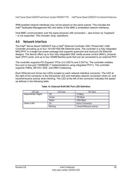
Each Ethernet port drives two LEDs located on each network interface connector. The LED at<br />
the right of the connector is the link/activity LED and indicates network connection when on, and<br />
transmit/receive activity when blinking. The LED at the left of the connector indicates link speed<br />
as defined in the following table.<br />
Table 14. External RJ45 NIC Port LED Definition<br />
LED Color LED State NIC State<br />
Green/Amber (Right) Off 10 Mbps<br />
Amber 100 Mbps<br />
Green 1000 Mbps<br />
Green (Left) On Active Connection<br />
Blinking Transmit/Receive activity<br />
Revision 0.8 <strong>Intel</strong> Confidential<br />
<strong>Intel</strong> order number G26942-003<br />
49


