Technical Product Specification for Canoe Pass - Preminary - Intel
Technical Product Specification for Canoe Pass - Preminary - Intel Technical Product Specification for Canoe Pass - Preminary - Intel
Intel ® Server System P4000CP Accessories Intel ® Server Board S2600CP and Server System P4000CP TPS 15.5.6 Capacitive Loading The power supply shall be stable and meet all requirements with the following capacitive loading ranges. 15.5.7 Grounding 160 Table 159. Capacitive Loading Conditions Output Min Max Units +3.3V 250 5000 F +5V 400 5000 F +12V 500 8000 F -12V 1 350 F +5VSB 20 350 F The output ground of the pins of the power supply provides the output power return path. The output connector ground pins shall be connected to the safety ground (power supply enclosure). This grounding should be well designed to ensure passing the max allowed Common Mode Noise levels. The power supply shall be provided with a reliable protective earth ground. All secondary circuits shall be connected to protective earth ground. Resistance of the ground returns to chassis shall not exceed 1.0 m. This path may be used to carry DC current. 15.5.8 Closed loop stability The power supply shall be unconditionally stable under all line/load/transient load conditions including capacitive load ranges specified in Section 4.6. A minimum of 45 degrees phase margin and -10dB-gain margin is required. The power supply manufacturer shall provide proof of the unit’s closed-loop stability with local sensing through the submission of Bode plots. Closed-loop stability must be ensured at the maximum and minimum loads as applicable. 15.5.9 Residual Voltage Immunity in Standby mode The power supply should be immune to any residual voltage placed on its outputs (Typically a leakage voltage through the system from standby output) up to 500mV. There shall be no additional heat generated, nor stressing of any internal components with this voltage applied to any individual or all outputs simultaneously. It also should not trip the protection circuits during turn on. The residual voltage at the power supply outputs for no load condition shall not exceed 100mV when AC voltage is applied and the PSON# signal is de-asserted. 15.5.10 Common Mode Noise The Common Mode noise on any output shall not exceed 350mV pk-pk over the frequency band of 10Hz to 20MHz. 1. The measurement shall be made across a 100Ω resistor between each of DC outputs, including ground at the DC power connector and chassis ground (power subsystem enclosure). 2. The test set-up shall use a FET probe such as Tektronix model P6046 or equivalent. Intel Confidential Revision 0.8 Intel order number G26942-003
Intel ® Server Board S2600CP and Server System P4000CP TPS Intel ® Server System P4000CP Accessories 15.5.11 Soft Starting The Power Supply shall contain control circuit which provides monotonic soft start for its outputs without overstress of the AC line or any power supply components at any specified AC line or load conditions. 15.5.12 Zero Load Stability Requirements When the power subsystem operates in a no load condition, it does not need to meet the output regulation specification, but it must operate without any tripping of over-voltage or other fault circuitry. When the power subsystem is subsequently loaded, it must begin to regulate and source current without fault. 15.5.13 Ripple/Noise The maximum allowed ripple/noise output of the power supply is defined in the table below. This is measured over a bandwidth of 10Hz to 20MHz at the power supply output connectors. A 10F tantalum capacitor in parallel with a 0.1F ceramic capacitor is placed at the point of measurement. The test set-up is shown below. Table 160. Ripples and Noise +3.3V +5V +12V1,2,3 -12V +5VSB 50mVp-p 50mVp-p 120mVp-p 200mVp-p 50mVp-p V OUT AC HOT POWER SUPPLY V AC NEUTRAL RETURN AC GROUND GENERAL NOTES: 1. LOAD THE OUTPUT WITH ITS MINIMUM LOAD CURRENT. 2. CONNECT THE PROBES AS SHOWN. 3. REPEAT THE MEASUREMENTS WITH THE MAXIMUM LOAD ON THE OUTPUT. 10uF .1uF Revision 0.8 Intel Confidential Intel order number G26942-003 LOAD LOAD MUST BE ISOLATED FROM THE GROUND OF THE POWER SUPPLY SCOPE SCOPE NOTE: USE A TEKTRONIX 7834 OSCILLOSCOPE WITH 7A13 AND DIFFERENTIAL PROBE P6055 OR EQUIVALENT. Figure 58. Differential Noise test setup Note: When performing this test, the probe clips and capacitors should be located close to the load. 15.5.14 Timing Requirements These are the timing requirements for the power supply operation. The output voltages must rise from 10% to within regulation limits (Tvout_rise) within 2 to 50ms, except for 5VSB - it is allowed to rise from 1 to 25ms. The +3.3V, +5V and +12V1,+12V2 ,+12V3 output voltages should start to rise approximately at the same time. All outputs must rise monotonically. Each output voltage shall reach regulation within 50ms (Tvout_on) of each other during turn on of the power supply. Each output voltage shall fall out of regulation within 400ms (Tvout_off) of each other during turn off. Table 162 shows the timing requirements for the power supply being 161
- Page 125 and 126: Intel ® Server Board S2600CP and S
- Page 127 and 128: Intel ® Server Board S2600CP and S
- Page 129 and 130: Intel ® Server Board S2600CP and S
- Page 131 and 132: Intel ® Server Board S2600CP and S
- Page 133 and 134: Intel ® Server Board S2600CP and S
- Page 135 and 136: Intel ® Server Board S2600CP and S
- Page 137 and 138: Intel ® Server Board S2600CP and S
- Page 139 and 140: Intel ® Server Board S2600CP and S
- Page 141 and 142: Intel ® Server Board S2600CP and S
- Page 143 and 144: Intel ® Server Board S2600CP and S
- Page 145 and 146: Intel ® Server Board S2600CP and S
- Page 147 and 148: Intel ® Server Board S2600CP and S
- Page 149 and 150: Intel ® Server Board S2600CP and S
- Page 151 and 152: Intel ® Server Board S2600CP and S
- Page 153 and 154: Intel ® Server Board S2600CP and S
- Page 155 and 156: Intel ® Server Board S2600CP and S
- Page 157 and 158: Intel ® Server Board S2600CP and S
- Page 159 and 160: Intel ® Server Board S2600CP and S
- Page 161 and 162: Intel ® Server Board S2600CP and S
- Page 163 and 164: Intel ® Server Board S2600CP and S
- Page 165 and 166: Intel ® Server Board S2600CP and S
- Page 167 and 168: Intel ® Server Board S2600CP and S
- Page 169 and 170: Intel ® Server Board S2600CP and S
- Page 171 and 172: Intel ® Server Board S2600CP and S
- Page 173 and 174: Intel® Server System P4000CP TPS D
- Page 175: Intel ® Server Board S2600CP and S
- Page 179 and 180: Intel ® Server Board S2600CP and S
- Page 181 and 182: Intel ® Server Board S2600CP and S
- Page 183 and 184: Intel® Server System P4000CP TPS A
- Page 185 and 186: Intel ® Server Board S2600CP and S
- Page 187 and 188: Intel ® Server Board S2600CP and S
- Page 189 and 190: Intel ® Server Board S2600CP and S
- Page 191 and 192: Intel ® Server Board S2600CP and S
- Page 193 and 194: Intel ® Server Board S2600CP and S
- Page 195 and 196: Intel ® Server Board S2600CP and S
- Page 197 and 198: Intel ® Server Board S2600CP and S
- Page 199 and 200: Intel ® Server Board S2600CP and S
- Page 201 and 202: Intel® Server System P4000CP TPS A
- Page 203 and 204: Intel® Server System P4000CP TPS A
- Page 205 and 206: Intel® Server System P4000CP TPS A
- Page 207 and 208: Intel® Server System P4000CP TPS A
- Page 209 and 210: Intel® Server System P4000CP TPS A
- Page 211 and 212: Error! No text of specified style i
- Page 213 and 214: Error! No text of specified style i
- Page 215 and 216: Error! No text of specified style i
- Page 217 and 218: ® Intel ® Server Board S2600CP an
- Page 219 and 220: ® Intel ® Server Board S2600CP an
<strong>Intel</strong> ® Server Board S2600CP and Server System P4000CP TPS <strong>Intel</strong> ® Server System P4000CP Accessories<br />
15.5.11 Soft Starting<br />
The Power Supply shall contain control circuit which provides monotonic soft start <strong>for</strong> its outputs<br />
without overstress of the AC line or any power supply components at any specified AC line or<br />
load conditions.<br />
15.5.12 Zero Load Stability Requirements<br />
When the power subsystem operates in a no load condition, it does not need to meet the output<br />
regulation specification, but it must operate without any tripping of over-voltage or other fault<br />
circuitry. When the power subsystem is subsequently loaded, it must begin to regulate and<br />
source current without fault.<br />
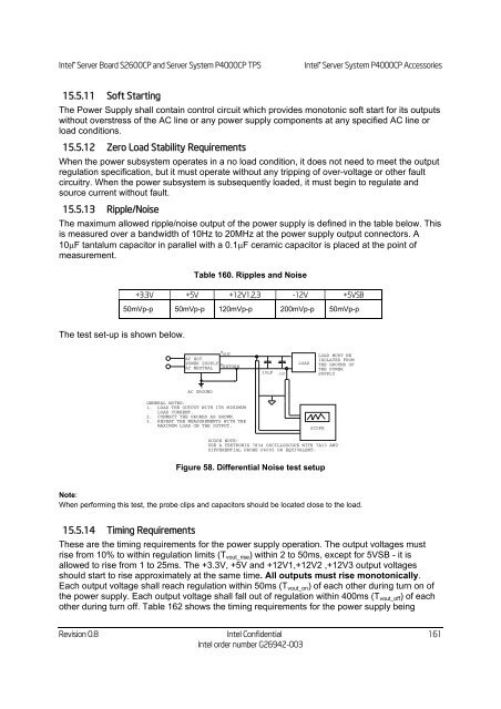
15.5.13 Ripple/Noise<br />
The maximum allowed ripple/noise output of the power supply is defined in the table below. This<br />
is measured over a bandwidth of 10Hz to 20MHz at the power supply output connectors. A<br />
10F tantalum capacitor in parallel with a 0.1F ceramic capacitor is placed at the point of<br />
measurement.<br />
The test set-up is shown below.<br />
Table 160. Ripples and Noise<br />
+3.3V +5V +12V1,2,3 -12V +5VSB<br />
50mVp-p 50mVp-p 120mVp-p 200mVp-p 50mVp-p<br />
V<br />
OUT<br />
AC HOT<br />
POWER SUPPLY<br />
V<br />
AC NEUTRAL RETURN<br />
AC GROUND<br />
GENERAL NOTES:<br />
1. LOAD THE OUTPUT WITH ITS MINIMUM<br />
LOAD CURRENT.<br />
2. CONNECT THE PROBES AS SHOWN.<br />
3. REPEAT THE MEASUREMENTS WITH THE<br />
MAXIMUM LOAD ON THE OUTPUT.<br />
10uF .1uF<br />
Revision 0.8 <strong>Intel</strong> Confidential<br />
<strong>Intel</strong> order number G26942-003<br />
LOAD<br />
LOAD MUST BE<br />
ISOLATED FROM<br />
THE GROUND OF<br />
THE POWER<br />
SUPPLY<br />
SCOPE<br />
SCOPE NOTE:<br />
USE A TEKTRONIX 7834 OSCILLOSCOPE WITH 7A13 AND<br />
DIFFERENTIAL PROBE P6055 OR EQUIVALENT.<br />
Figure 58. Differential Noise test setup<br />
Note:<br />
When per<strong>for</strong>ming this test, the probe clips and capacitors should be located close to the load.<br />
15.5.14 Timing Requirements<br />
These are the timing requirements <strong>for</strong> the power supply operation. The output voltages must<br />
rise from 10% to within regulation limits (Tvout_rise) within 2 to 50ms, except <strong>for</strong> 5VSB - it is<br />
allowed to rise from 1 to 25ms. The +3.3V, +5V and +12V1,+12V2 ,+12V3 output voltages<br />
should start to rise approximately at the same time. All outputs must rise monotonically.<br />
Each output voltage shall reach regulation within 50ms (Tvout_on) of each other during turn on of<br />
the power supply. Each output voltage shall fall out of regulation within 400ms (Tvout_off) of each<br />
other during turn off. Table 162 shows the timing requirements <strong>for</strong> the power supply being<br />
161


