Technical Product Specification for Canoe Pass - Preminary - Intel
Technical Product Specification for Canoe Pass - Preminary - Intel
Technical Product Specification for Canoe Pass - Preminary - Intel

Create successful ePaper yourself
Turn your PDF publications into a flip-book with our unique Google optimized e-Paper software.
<strong>Intel</strong> ® Server Board S2600CP and Server System P4000CP TPS <strong>Intel</strong> ® Server System P4000CP Power System Options<br />
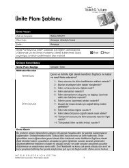
The test set-up shall be as shown below.<br />
50mVp-p 50mVp-p 120mVp-p 50mVp-p<br />
V<br />
OUT<br />
AC HOT<br />
POWER SUPPLY<br />
V<br />
AC NEUTRAL RETURN<br />
AC GROUND<br />
GENERAL NOTES:<br />
1. LOAD THE OUTPUT WITH ITS MINIMUM<br />
LOAD CURRENT.<br />
2. CONNECT THE PROBES AS SHOWN.<br />
3. REPEAT THE MEASUREMENTS WITH THE<br />
MAXIMUM LOAD ON THE OUTPUT.<br />
10uF .1uF<br />
Revision 0.8 <strong>Intel</strong> Confidential<br />
<strong>Intel</strong> order number G26942-003<br />
LOAD<br />
LOAD MUST BE<br />
ISOLATED FROM<br />
THE GROUND OF<br />
THE POWER<br />
SUPPLY<br />
SCOPE<br />
SCOPE NOTE:<br />
USE A TEKTRONIX 7834 OSCILLOSCOPE WITH 7A13 AND<br />
DIFFERENTIAL PROBE P6055 OR EQUIVALENT.<br />
Note:<br />
When per<strong>for</strong>ming this test, the probe clips and capacitors should be located close to the load.<br />
Figure 55. Differential Noise test setup<br />
13.5.2.15 Timing Requirements<br />
Below are timing requirements <strong>for</strong> the power on/off of the PDB DC/DC converters. The +3.3V,<br />
+5V and +12V output voltages should start to rise approximately at the same time. All outputs<br />
must rise monotonically.<br />
Table 145. Output Voltage Timing<br />
Description Min Max Units<br />
Output voltage rise time <strong>for</strong> each main output; 3.3V, 5V, -12V<br />
and 5Vstby.<br />
1.0 20 msec<br />
The main DC/DC converters (3.3V, 5V, -12V) shall be in<br />
regulation limits within this time after the 12V input has<br />
reached 11.4V.<br />
The main DC/DC converters (3.3V, 5V, -12V) must drop<br />
below regulation limits within this time after the 12V input has<br />
dropped below 11.4V.<br />
The 5Vstby converter shall be in regulation limits within this<br />
time after the 12Vstby has reach 11.4V.<br />
The 5Vstby converter must power off within this time after the<br />
12Vstby input has dropped below 11.4V.<br />
20 msec<br />
20 msec<br />
20 msec<br />
20 msec<br />
13.5.2.16 Residual Voltage Immunity in Standby Mode<br />
Each DC/DC converter is immune to any residual voltage placed on its respective output<br />
(typically a leakage voltage through the system from standby output) up to 500mV. This residual<br />
voltage does not have any adverse effect on each DC/DC converter, such as: no additional<br />
power dissipation or over-stressing/over-heating any internal components or adversely affecting<br />
the turn-on per<strong>for</strong>mance (no protection circuits tripping during turn on).<br />
While in Stand-by mode, at no load condition, the residual voltage on each DC/DC converter<br />
output does not exceed 100mV.<br />
149