Technical Product Specification for Canoe Pass - Preminary - Intel
Technical Product Specification for Canoe Pass - Preminary - Intel Technical Product Specification for Canoe Pass - Preminary - Intel
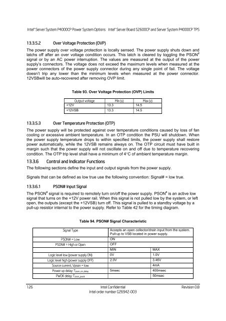
Intel ® Server System P4000CP Power System Options Intel ® Server Board S2600CP and Server System P4000CP TPS 13.3.5.2 Over Voltage Protection (OVP) The power supply over voltage protection is locally sensed. The power supply shuts down and latchs off after an over voltage condition occurs. This latch is cleared by toggling the PSON # signal or by an AC power interruption. The values are measured at the output of the power supply’s connectors. The voltage does not exceed the maximum levels when measured at the power connectors of the power supply connector during any single point of fail. The voltage doesn’t trip any lower than the minimum levels when measured at the power connector. 12VSBwill be auto-recovered after removing OVP limit. 126 Table 93. Over Voltage Protection (OVP) Limits Output voltage Min (v) Max (v) +12V 13.3 14.5 +12VSB 13.3 14.5 13.3.5.3 Over Temperature Protection (OTP) The power supply will be protected against over temperature conditions caused by loss of fan cooling or excessive ambient temperature. In an OTP condition the PSU will shutdown. When the power supply temperature drops to within specified limits, the power supply shall restore power automatically, while the 12VSB remains always on. The OTP circuit must have built in margin such that the power supply will not oscillate on and off due to temperature recovering condition. The OTP trip level shall have a minimum of 4C of ambient temperature margin. 13.3.6 Control and Indicator Functions The following sections define the input and output signals from the power supply. Signals that can be defined as low true use the following convention: Signal# = low true. 13.3.6.1 PSON# Input Signal The PSON # signal is required to remotely turn on/off the power supply. PSON # is an active low signal that turns on the +12V power rail. When this signal is not pulled low by the system, or left open, the outputs (except the +12VSB) turn off. This signal is pulled to a standby voltage by a pull-up resistor internal to the power supply. Refer to Table 42 for the timing diagram. Signal Type PSON# = Low PSON# = High or Open Table 94. PSON# Signal Characteristic Accepts an open collector/drain input from the system. Pull-up to VSB located in power supply. ON OFF MIN MAX Logic level low (power supply ON) 0V 1.0V Logic level high (power supply OFF) 2.0V 3.46V Source current, Vpson = low 4mA Power up delay: Tpson_on_delay 5msec 400msec PWOK delay: Tpson_pwok 50msec Intel Confidential Revision 0.8 Intel order number G26942-003
Intel ® Server Board S2600CP and Server System P4000CP TPS Intel ® Server System P4000CP Power System Options 0V 1.0 2.0 3.46V V V Figure 49. PSON# Required Signal Characteristic. 13.3.6.2 PWOK (Power OK) Output Signal PWOK is a power OK signal and will be pulled HIGH by the power supply to indicate that all the outputs are within the regulation limits of the power supply. When any output voltage falls below regulation limits or when AC power has been removed for a time sufficiently long so that power supply operation is no longer guaranteed, PWOK will be de-asserted to a LOW state. See Table 46 for a representation of the timing characteristics of PWOK. The start of the PWOK delay time shall inhibited as long as any power supply output is in current limit. Signal Type PWOK = High PWOK = Low Disabled Enabled 0.3V ≤ Hysterisis ≤ 1.0V In 1.0-2.0V input voltages range is required 1.0 V PS is enable d Table 95. PWOK Signal Characteristics Revision 0.8 Intel Confidential Intel order number G26942-003 Open collector/drain output from power supply. Pull-up to VSB located in the power supply. Power OK Power Not OK 2.0 V PS is disable d MIN MAX Logic level low voltage, Isink=400uA 0V 0.4V Logic level high voltage, Isource=200A 2.4V 3.46V Sink current, PWOK = low 400uA Source current, PWOK = high 2mA PWOK delay: Tpwok_on 100ms 1000ms PWOK rise and fall time 100sec Power down delay: Tpwok_off 1ms 200msec A recommended implementation of the Power Ok circuits is shown below. Note: the Power Ok circuits should be compatible with 5V pull up resistor (>10k) and 3.3V pull up resistor (>6.8k). 127
- Page 91 and 92: Intel ® Server Board S2600CP and S
- Page 93 and 94: Intel ® Server Board S2600CP and S
- Page 95 and 96: Intel ® Server Board S2600CP and S
- Page 97 and 98: Intel ® Server Board S2600CP and S
- Page 99 and 100: Intel ® Server Board S2600CP and S
- Page 101 and 102: Intel ® Server Board S2600CP and S
- Page 103 and 104: Intel ® Server Board S2600CP and S
- Page 105 and 106: Intel ® Server Board S2600CP and S
- Page 107 and 108: Intel ® Server Board S2600CP and S
- Page 109 and 110: Intel ® Server Board S2600CP and S
- Page 111 and 112: Intel ® Server Board S2600CP and S
- Page 113 and 114: Intel ® Server Board S2600CP and S
- Page 115 and 116: Intel ® Server Board S2600CP and S
- Page 117 and 118: Intel ® Server Board S2600CP and S
- Page 119 and 120: Intel ® Server Board S2600CP and S
- Page 121 and 122: Intel ® Server Board S2600CP and S
- Page 123 and 124: Intel ® Server Board S2600CP and S
- Page 125 and 126: Intel ® Server Board S2600CP and S
- Page 127 and 128: Intel ® Server Board S2600CP and S
- Page 129 and 130: Intel ® Server Board S2600CP and S
- Page 131 and 132: Intel ® Server Board S2600CP and S
- Page 133 and 134: Intel ® Server Board S2600CP and S
- Page 135 and 136: Intel ® Server Board S2600CP and S
- Page 137 and 138: Intel ® Server Board S2600CP and S
- Page 139 and 140: Intel ® Server Board S2600CP and S
- Page 141: Intel ® Server Board S2600CP and S
- Page 145 and 146: Intel ® Server Board S2600CP and S
- Page 147 and 148: Intel ® Server Board S2600CP and S
- Page 149 and 150: Intel ® Server Board S2600CP and S
- Page 151 and 152: Intel ® Server Board S2600CP and S
- Page 153 and 154: Intel ® Server Board S2600CP and S
- Page 155 and 156: Intel ® Server Board S2600CP and S
- Page 157 and 158: Intel ® Server Board S2600CP and S
- Page 159 and 160: Intel ® Server Board S2600CP and S
- Page 161 and 162: Intel ® Server Board S2600CP and S
- Page 163 and 164: Intel ® Server Board S2600CP and S
- Page 165 and 166: Intel ® Server Board S2600CP and S
- Page 167 and 168: Intel ® Server Board S2600CP and S
- Page 169 and 170: Intel ® Server Board S2600CP and S
- Page 171 and 172: Intel ® Server Board S2600CP and S
- Page 173 and 174: Intel® Server System P4000CP TPS D
- Page 175 and 176: Intel ® Server Board S2600CP and S
- Page 177 and 178: Intel ® Server Board S2600CP and S
- Page 179 and 180: Intel ® Server Board S2600CP and S
- Page 181 and 182: Intel ® Server Board S2600CP and S
- Page 183 and 184: Intel® Server System P4000CP TPS A
- Page 185 and 186: Intel ® Server Board S2600CP and S
- Page 187 and 188: Intel ® Server Board S2600CP and S
- Page 189 and 190: Intel ® Server Board S2600CP and S
- Page 191 and 192: Intel ® Server Board S2600CP and S
<strong>Intel</strong> ® Server System P4000CP Power System Options <strong>Intel</strong> ® Server Board S2600CP and Server System P4000CP TPS<br />
13.3.5.2 Over Voltage Protection (OVP)<br />
The power supply over voltage protection is locally sensed. The power supply shuts down and<br />
latchs off after an over voltage condition occurs. This latch is cleared by toggling the PSON #<br />
signal or by an AC power interruption. The values are measured at the output of the power<br />
supply’s connectors. The voltage does not exceed the maximum levels when measured at the<br />
power connectors of the power supply connector during any single point of fail. The voltage<br />
doesn’t trip any lower than the minimum levels when measured at the power connector.<br />
12VSBwill be auto-recovered after removing OVP limit.<br />
126<br />
Table 93. Over Voltage Protection (OVP) Limits<br />
Output voltage Min (v) Max (v)<br />
+12V 13.3 14.5<br />
+12VSB 13.3 14.5<br />
13.3.5.3 Over Temperature Protection (OTP)<br />
The power supply will be protected against over temperature conditions caused by loss of fan<br />
cooling or excessive ambient temperature. In an OTP condition the PSU will shutdown. When<br />
the power supply temperature drops to within specified limits, the power supply shall restore<br />
power automatically, while the 12VSB remains always on. The OTP circuit must have built in<br />
margin such that the power supply will not oscillate on and off due to temperature recovering<br />
condition. The OTP trip level shall have a minimum of 4C of ambient temperature margin.<br />
13.3.6 Control and Indicator Functions<br />
The following sections define the input and output signals from the power supply.<br />
Signals that can be defined as low true use the following convention: Signal# = low true.<br />
13.3.6.1 PSON# Input Signal<br />
The PSON # signal is required to remotely turn on/off the power supply. PSON # is an active low<br />
signal that turns on the +12V power rail. When this signal is not pulled low by the system, or left<br />
open, the outputs (except the +12VSB) turn off. This signal is pulled to a standby voltage by a<br />
pull-up resistor internal to the power supply. Refer to Table 42 <strong>for</strong> the timing diagram.<br />
Signal Type<br />
PSON# = Low<br />
PSON# = High or Open<br />
Table 94. PSON# Signal Characteristic<br />
Accepts an open collector/drain input from the system.<br />
Pull-up to VSB located in power supply.<br />
ON<br />
OFF<br />
MIN MAX<br />
Logic level low (power supply ON) 0V 1.0V<br />
Logic level high (power supply OFF) 2.0V 3.46V<br />
Source current, Vpson = low 4mA<br />
Power up delay: Tpson_on_delay 5msec 400msec<br />
PWOK delay: Tpson_pwok 50msec<br />
<strong>Intel</strong> Confidential Revision 0.8<br />
<strong>Intel</strong> order number G26942-003


