the effect of the particle size distribution on non-newtonian turbulent ...
the effect of the particle size distribution on non-newtonian turbulent ...
the effect of the particle size distribution on non-newtonian turbulent ...

Create successful ePaper yourself
Turn your PDF publications into a flip-book with our unique Google optimized e-Paper software.
Chapter 3 Experimental Work Page 3.6<br />
3.2.2 Mini Rig<br />
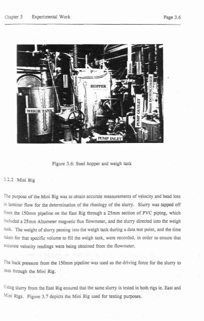
Figure 3.6: Steel hopper and weigh tank<br />
The purpose <str<strong>on</strong>g>of</str<strong>on</strong>g> <str<strong>on</strong>g>the</str<strong>on</strong>g> Mini Rig was to obtain accurate measurements <str<strong>on</strong>g>of</str<strong>on</strong>g> velocity and head loss<br />
in laminar flow for <str<strong>on</strong>g>the</str<strong>on</strong>g> determinati<strong>on</strong> <str<strong>on</strong>g>of</str<strong>on</strong>g> <str<strong>on</strong>g>the</str<strong>on</strong>g> rheology <str<strong>on</strong>g>of</str<strong>on</strong>g> <str<strong>on</strong>g>the</str<strong>on</strong>g> slurry. Slurry was tapped <str<strong>on</strong>g>of</str<strong>on</strong>g>f<br />
from <str<strong>on</strong>g>the</str<strong>on</strong>g> 150rnrn pipeline <strong>on</strong> <str<strong>on</strong>g>the</str<strong>on</strong>g> East Rig through a 25mm secti<strong>on</strong> <str<strong>on</strong>g>of</str<strong>on</strong>g> PVC piping, which<br />
included a 25mm Altometer magnetic flux flowmeter, and <str<strong>on</strong>g>the</str<strong>on</strong>g> slurry directed into <str<strong>on</strong>g>the</str<strong>on</strong>g> weigh<br />
tank. The weight <str<strong>on</strong>g>of</str<strong>on</strong>g> slurry passing into <str<strong>on</strong>g>the</str<strong>on</strong>g> weigh tank during a data test point, and <str<strong>on</strong>g>the</str<strong>on</strong>g> time<br />
taken for that specific volume to ftIl <str<strong>on</strong>g>the</str<strong>on</strong>g> weigh tank, were recorded, in order to ensure that<br />
aCCurate velocity readings were being obtained from <str<strong>on</strong>g>the</str<strong>on</strong>g> flowmeter.<br />
The back pressure from <str<strong>on</strong>g>the</str<strong>on</strong>g> 150mm pipeline was used as <str<strong>on</strong>g>the</str<strong>on</strong>g> driving force for <str<strong>on</strong>g>the</str<strong>on</strong>g> slurry to<br />
pass through <str<strong>on</strong>g>the</str<strong>on</strong>g> Mini Rig.<br />
Using slurry from <str<strong>on</strong>g>the</str<strong>on</strong>g> East Rig ensured that <str<strong>on</strong>g>the</str<strong>on</strong>g> same slurry is tested in both rigs ie. East and<br />
Mini Rigs. Figure 3.7 depicts <str<strong>on</strong>g>the</str<strong>on</strong>g> Mini Rig used for testing purposes.