show voice port - Tecnológico de Costa Rica
show voice port - Tecnológico de Costa Rica show voice port - Tecnológico de Costa Rica
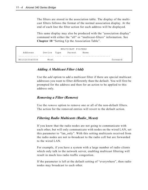
11 - 4 Aironet 340 Series Bridge The filters are stored in the association table. The display of the multicast filters follows the format of the normal association display. At the end of each line the filter action for each address will be displayed. This same display may also be produced with the “association display” command with either the “all” or “multicast-filters” information. See Chapter 10 “Setting Up the Association Table”. MULTICAST FILTERS Address Device Type Parent Name ------------- --------- ---- ------------ ------------------ N010203040506 Mcst forward Adding A Multicast Filter (Add) Use the add option to add a multicast filter if there are special multicast addresses you want to filter differently than the default. You will first be prompted for the address and then for an action to be applied to this address only. Removing a Filter (Remove) Use the remove option to remove one or all of the non-default filters. The action for the removed entries will revert to the default action. Filtering Radio Multicasts (Radio_Mcast) If you know that the radio nodes are not going to communicate with each other, but will only communicate with nodes on the wired LAN, set this parameter to “lan_only”. With this setting multicasts received from the radio nodes are not re-broadcast to the radio cell but are forwarded to the wired LAN. For example, if you have a system with a large number of radio clients which only talk to the network server, enabling multicast filtering will result in much less radio traffic congestion. If the parameter is left at the default setting of “everywhere”, then radio nodes may broadcast to each other.
Filtering Node Addresses (Node) Using Filters 11 - 5 The node option allows you to control the forwarding of packets based on the source node addresses. As with multicast filtering, there is a default action for those addresses not in the table. You may enter actions for specific addresses to override the default action. Specific node filters may be entered by specifying either the 6 byte infrastructure address of the node or by specifying its IP address. If the IP address is used, the Aironet 340 Series Bridge will determine the infrastructure address associated with the IP address and use this for the actual filtering. You may filter packets based on the source address in the received packet. For example, if you wanted to prevent all but a limited number of hosts to communicate with nodes on the radio network, you would set the default action to discard. Then add entries for the specific hosts whose action is “forward”. Filter Node Menu Option Value Description 1 - Ethdst [ forward ] - Destination address from ethernet 2 - Raddst [ forward ] - Destination address from radio 3 - Source [ off ] - Source addresses 4 - Display - Display the node address filters 5 - Ipdisplay - Display the IP address filters 6 - Add - Add a node address filter 7 - Remove - Remove a node address filter Enter an option number or name, “=” main menu, previous menu >_ Setting the Destination Address (Ethdst and Raddst) The unit is always performing filtering based on the destination MAC address of the packets it receives. The Bridge will learn where a node is based on the source address of received packets and then can make a decision as to whether to forward a packet based on its knowledge of the location of the node. These options set the default actions when doing destination address filtering. The Ethdst value specifies the default action for packets received on the ethernet. The Raddst action specifies the default action for packet received on the radio interface. The value allowed are discard or forward.
- Page 373 and 374: 6 - 2 Aironet 340 Series Bridge Usi
- Page 375 and 376: 6 - 4 Aironet 340 Series Bridge 2.
- Page 377 and 378: Chapter 7 - Configuring Mobile IP C
- Page 379 and 380: Configuring Mobile IP 7 - 3 On a fo
- Page 381 and 382: Configuring Mobile IP 7 - 5 work. T
- Page 383 and 384: Chapter 8 - Using the Spanning Tree
- Page 385 and 386: Understanding Loops Using the Spann
- Page 387 and 388: Using the Spanning-Tree Protocol 8
- Page 389 and 390: Establishing Timeouts Node Address
- Page 391 and 392: Using the Configuration STP Menu (R
- Page 393 and 394: Using the Spanning-Tree Protocol 8
- Page 395 and 396: Using the Spanning-Tree Protocol 8
- Page 397 and 398: Setting the Local Port Priority (Pr
- Page 399 and 400: Viewing the Port State (State) Usin
- Page 401 and 402: Chapter 9 - Viewing Statistics CHAP
- Page 403 and 404: Throughput Statistics (Throughput)
- Page 405 and 406: Error Statistics Viewing Statistics
- Page 407 and 408: Displaying Overall Status (Status)
- Page 409 and 410: Viewing Statistics 9 - 9 2. Type th
- Page 411 and 412: Displaying Node Information (Node)
- Page 413 and 414: Chapter 10 - Setting Up the Associa
- Page 415 and 416: Using the Association Menu Setting
- Page 417 and 418: Setting Up the Association Table 10
- Page 419 and 420: Setting Up the Association Table 10
- Page 421 and 422: Chapter 11 - Using Filters CHAPTER
- Page 423: Using Filters 11 - 3 n Both: Packet
- Page 427 and 428: Displaying the IP to Network Addres
- Page 429 and 430: Setting the Default Action (Default
- Page 431 and 432: Í To Add a Filter Using the Monito
- Page 433 and 434: If you type llc: a. When you select
- Page 435 and 436: Using Filters 11 - 15 The contents
- Page 437 and 438: Chapter 12 - Setting Up Event Logs
- Page 439 and 440: Setting Up Event Logs 12 - 3 Node
- Page 441 and 442: Error Logs Severe Error Logs “Cat
- Page 443 and 444: Lost our association, new specified
- Page 445 and 446: Setting Up Event Logs 12 - 9 NOTE:
- Page 447 and 448: Setting Statistic Parameters (Stati
- Page 449 and 450: The following trap messages will be
- Page 451 and 452: Chapter 13 - Performing Diagnostics
- Page 453 and 454: Performing Diagnostics 13 - 3 are d
- Page 455 and 456: Physically Locating a Unit (Find) P
- Page 457 and 458: Performing Diagnostics 13 - 7 4. Th
- Page 459 and 460: Performing Diagnostics 13 - 9 5. Se
- Page 461 and 462: Performing Diagnostics 13 - 11 4. I
- Page 463 and 464: Performing Diagnostics 13 - 13 If t
- Page 465 and 466: Appendix A - Aironet 340 Series Bri
- Page 467 and 468: Console Port Pin-Out The Console Po
- Page 469 and 470: B-2 Aironet 340 Series Bridge Conti
- Page 471 and 472: B-4 Aironet 340 Series Bridge Broad
- Page 473 and 474: B-6 Aironet 340 Series Bridge Desti
11 - 4 Aironet 340 Series Bridge<br />
The filters are stored in the association table. The display of the multicast<br />
filters follows the format of the normal association display. At the<br />
end of each line the filter action for each address will be displayed.<br />
This same display may also be produced with the “association display”<br />
command with either the “all” or “multicast-filters” information. See<br />
Chapter 10 “Setting Up the Association Table”.<br />
MULTICAST FILTERS<br />
Address Device Type Parent Name<br />
------------- --------- ---- ------------ ------------------<br />
N010203040506 Mcst forward<br />
Adding A Multicast Filter (Add)<br />
Use the add option to add a multicast filter if there are special multicast<br />
addresses you want to filter differently than the <strong>de</strong>fault. You will first be<br />
prompted for the address and then for an action to be applied to this<br />
address only.<br />
Removing a Filter (Remove)<br />
Use the remove option to remove one or all of the non-<strong>de</strong>fault filters.<br />
The action for the removed entries will revert to the <strong>de</strong>fault action.<br />
Filtering Radio Multicasts (Radio_Mcast)<br />
If you know that the radio no<strong>de</strong>s are not going to communicate with<br />
each other, but will only communicate with no<strong>de</strong>s on the wired LAN, set<br />
this parameter to “lan_only”. With this setting multicasts received from<br />
the radio no<strong>de</strong>s are not re-broadcast to the radio cell but are forwar<strong>de</strong>d<br />
to the wired LAN.<br />
For example, if you have a system with a large number of radio clients<br />
which only talk to the network server, enabling multicast filtering will<br />
result in much less radio traffic congestion.<br />
If the parameter is left at the <strong>de</strong>fault setting of “everywhere”, then radio<br />
no<strong>de</strong>s may broadcast to each other.


