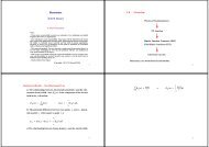
dB =10log P1 P2
dB =10log P1 P2
dB =10log P1 P2

Create successful ePaper yourself
Turn your PDF publications into a flip-book with our unique Google optimized e-Paper software.
! Results from the losses in the transmission<br />
medium<br />
! Guided media<br />
! Signal strength decays exponentially<br />
! May be expressed as a logarithmic power ratio<br />
Power _ ratio_in _ <strong>dB</strong> <strong>=10log</strong> P 1<br />
P 2<br />
3<br />
Covered in Transmission<br />
Line & Interface Design<br />
unit<br />
2<br />
4
Addition or subtraction of <strong>dB</strong> yields the system loss/gain between 2<br />
points<br />
<strong>dB</strong> level at point 4=(-9)+(14)+(-3)=+2<strong>dB</strong><br />
<strong>dB</strong> is a ratio and gives no indication of absolute power levels<br />
! Various noise and disturbances may cause<br />
errors in interpreting the received signal<br />
! Thermal noise<br />
! Uniform distribution across the frequency spectrum<br />
! White noise<br />
! Random errors<br />
! Does not (normally) effect the following bit interval<br />
5<br />
! Delay effects<br />
! Multipath propagation effects in wireless<br />
! Skew in parallel ports or busses<br />
! Signals consist of various frequency<br />
components<br />
! Each propagate at different speeds in guided<br />
medium<br />
! Results in phase shift at the receiver<br />
! Intersymbol interference<br />
! Receiver must extract timing from the<br />
incoming signal<br />
! Allows sampling when SNR is at maximum<br />
! Maintain intersymbol spacing<br />
! Indicates start/end of each timing interval<br />
! Inclusion of error detecting/correcting<br />
! Introduce additional bits into the raw data stream<br />
! Channel line encoding<br />
7 8<br />
6
! The end-to-end transfer of data from a<br />
transmitting application to a receiving<br />
application involves many steps<br />
! Each subject to error.<br />
! Errors can occur both at the bit and at the packet<br />
level.<br />
! At the bit level, the most common error is bit<br />
corruption<br />
! At the packet level, we see errors such as packet<br />
loss, duplication, or reordering.<br />
! Error control is the process of detecting and<br />
correcting both bit and packet errors.<br />
Nyquist Theorem<br />
Sample rate of at least<br />
twice the maximum<br />
frequency component of<br />
the signal to be<br />
digitised<br />
Aliasing occurs<br />
Quantizing noise<br />
9 10<br />
11<br />
! Bit-level error control usually involves adding<br />
redundancy to the transmitted data.<br />
! In some schemes, there is sufficient information for<br />
the receiver not only to detect errors, but also to<br />
correct most of them.<br />
! At the packet level, we assume that bit-level error<br />
control can detect all bit errors.<br />
! (Detectable but uncorrectable bit errors are treated<br />
as a packet loss.)<br />
12
! Packet-level error control mechanisms detect<br />
and correct packet-level errors such as loss,<br />
duplication, and reordering.<br />
! We typically implement bit-level error control<br />
at the datalink layer of the protocol stack.<br />
! Packet-level error control is typically found at<br />
the transport layer.<br />
! Thus, bit level error control is usually hop-by-hop,<br />
whereas packet-level error control is usually end-toend.<br />
! Information is transmitted on a link by<br />
varying the state of a signal.<br />
! On a digital link, each signal state<br />
corresponds to one or more 0's and 1's-a<br />
signal that can take 2 n , states represents n<br />
bits of information. To decipher a signal on a<br />
digital link, the receiver compares the<br />
received signal with a set of predefined<br />
references.<br />
13<br />
15<br />
! Generally speaking, we prefer hop-by-hop<br />
error control on links where the error rate is<br />
high (so-called lossy links) and end-to-end<br />
error control when entire path is more or less<br />
error free.<br />
! We usually measure the error probability on a<br />
digital link in terms of the bit error rate or<br />
BER<br />
! the ratio of the mean number of errors in any given<br />
interval to the total number of bits transmitted in<br />
that interval.<br />
! Typical fiber-optic links have a bit error ratio in the<br />
range of 10 -18 - 10 -14 , but copper links can have a<br />
substantially higher bit error ratio, depending on<br />
shielding and the operating environment.<br />
14<br />
16
! The major causes of bit errors are Gaussian<br />
and non-Gaussian noise, loss of line<br />
synchronisation, scramblers, protection<br />
switching, and, for cellular communication,<br />
handoffs and fading<br />
! A third source of bit errors is loss of bit<br />
synchronisation between the transmitter and<br />
the receiver.<br />
! Receivers periodically sample the received<br />
analog waveform to extract digital<br />
information.<br />
! They typically use the transitions in the<br />
transmitter's signal as the input to a phaselocked<br />
loop to determine the transmitter's<br />
clock automatically.<br />
17<br />
19<br />
! Gaussian noise<br />
! A common assumption is that the noise amplitude is<br />
described by a Gaussian (normal) distribution. We call<br />
such noise Gaussian noise. Gaussian noise on a line<br />
leads to uncorrelated and sporadic bit errors.<br />
! Non-Gaussian noise<br />
! Non-Gaussian noise, which refers to noise that does not<br />
obey a Gaussian distribution, can lead to bursts of<br />
errors. Common sources of non-Gaussian noise are<br />
electrical impulses, such as lightning or electrical sparks.<br />
! Handoffs and fading can cause error bursts in<br />
cellular communication.<br />
! A mobile unit is switched from one base station<br />
to another. It is common for some information<br />
from the mobile unit to be lost in this process.<br />
! Although voice callers may not notice this, data<br />
sources (such as modems) can be badly hit.<br />
! Typical handoffs last for about 150 ms during which<br />
time the received signal is almost completely in error.<br />
18<br />
20
! Handoff errors can be substantially reduced<br />
by making the new connection before the old<br />
one ends.<br />
! However, this makes it necessary to overlap basestation<br />
ranges, which leads to less efficient spatial<br />
reuse of the radio spectrum.<br />
! Two important functions<br />
! Flow control<br />
! Error control<br />
! Communication systems have limitations<br />
! Speed at which they process incoming data<br />
! Buffer space<br />
! Flow control enables the receiver to regulate data<br />
flow<br />
! Invokes a control procedure known as an acknowledgement<br />
(ACK)<br />
! Two common methods<br />
! Stop and wait<br />
! Sliding window<br />
21<br />
23<br />
! If a mobile station does not receive a strong<br />
signal from a base station because of hills,<br />
buildings, or other obstacles, then its<br />
received signal is in error until the unit moves<br />
away from the obstacle.<br />
! We call this loss of signal strength fading, and it<br />
causes long burst errors. There are two types of<br />
fading: shadow fading, which is due to macroscopic<br />
environmental conditions, and short-term Rayleigh<br />
fading, primarily due to vehicle movement.<br />
! Simple<br />
! Inefficient<br />
! Sender sends a frame and waits for an ACK<br />
! Must wait at least 2t prop plus t f (time to<br />
process the incoming frame)<br />
! No out of order frames<br />
22<br />
24
! Refers to the method used to detect and<br />
correct errors that occur in the transmission<br />
of frames<br />
! Retransmission of errored or dropped frames<br />
! Utilises ACK and NACK<br />
! Automatic Repeat Request (ARQ)<br />
! Three types<br />
! Stop and Wait<br />
! Go-back N<br />
! Selective repeat<br />
! May transmit several frames without receiving<br />
ACK<br />
! A single ACK may acknowledge many frames<br />
! Utilises an identification scheme based on the<br />
size of the window<br />
! Numbered modulo n, where n=window size-1<br />
! ACK is usually sent prior to window size<br />
reducing to zero<br />
25 26<br />
27<br />
! Basically stop and wait flow control<br />
! Extended to include NACK<br />
! Source sends a single frame<br />
! Waits for an ACK or NACK<br />
! Timer counts down 2 tprop plus t f<br />
! Very inefficient<br />
28
! Based on sliding window<br />
! AKA continuous ARQ<br />
! N specifies how many frames may be sent without<br />
an ACK or NACK<br />
! Receiver discards all incoming frames after an<br />
error<br />
! Waits to receive correctly the errored frame<br />
! Sender must retransmit all frames after the one in<br />
error, hence go back N<br />
! Also includes a timer<br />
! More efficient and requires no re-ordering at the<br />
receiver<br />
29<br />
! Only lost or damaged frames retransmitted<br />
! More efficient<br />
! From the utilisation viewpoint<br />
! Complex implementation<br />
! Re-ordering of retransmitted frames<br />
! Not often used<br />
31 32<br />
30
! Synchronous bit pipe<br />
! Sending side of DLC supplies the sending side modem bits at a fixed rate<br />
(one bit per T seconds)<br />
! Idle fill (dummy bits) when no data<br />
! Intermittent Synchronous bit pipe<br />
! Supplies synchronously when there is data to be sent<br />
! Sends nothing when no data<br />
! Receiver complications:<br />
! need to distinguish between 0, 1 and idle<br />
! Re-synchronize with sender at end of idle period<br />
! Asynchronous character pipe<br />
! Bits within a character sent at a fixed rate<br />
! Characters separated by variable delays<br />
! We need to decide where a frame starts and<br />
ends<br />
! Character based framing<br />
! Uses special characters<br />
! SYN for idle and fill<br />
! STX Start transmission<br />
! ETX End Transmission<br />
! Bit Oriented Framing<br />
! Special string of bits 01111110<br />
! Start, end and fill<br />
! Length count<br />
! Gives the frame length in a header field<br />
33<br />
35<br />
• In asynch serial communication, the electrical interface is held in the mark position between<br />
characters. The start of transmission of a character is signaled by a drop in signal level to the space<br />
level. At this point, the receiver starts its clock. After one bit time (the start bit) come 7 or 8 bits of<br />
true data followed by one or more stop bits at the mark level. The receiver tries to<br />
sample the signal in the middle of each bit time. The byte will be read correctly if the line is still in<br />
the intended state when the last stop bit is read.<br />
! Frames consist of integer number of bytes<br />
! Asynchronous transmission systems using ASCII to transmit printable<br />
characters<br />
! Octets with HEX value
! When sending arbitrary data (not characters)<br />
control characters may appear in frame<br />
! SOLUTION: Transparent Mode: Introduce DLE<br />
! Start of text: DLE STX, End of text: DLE ETX<br />
! If DLE appears in packet?<br />
! Use DLE DLE (receiver strips first DLE of pair)<br />
Data to be sent<br />
A DLE B ETX DLE STX E<br />
After stuffing and framing<br />
DLE STX A DLE DLE B ETX DLE DLE STX E DLE ETX<br />
HDLC frame<br />
Flag<br />
Address Control Information FCS<br />
any number of bits<br />
! Frame delineated by flag character<br />
! HDLC uses bit stuffing to prevent occurrence of flag<br />
01111110 inside the frame<br />
! Transmitter inserts extra 0 after each consecutive five<br />
1s inside the frame<br />
! Receiver checks for five consecutive 1s<br />
! if next bit = 0, it is removed<br />
! if next two bits are 10, then flag is detected<br />
! If next two bits are 11, then frame has errors<br />
37<br />
Flag<br />
(a)<br />
! Errors in header and packet caught by CRC<br />
! Errors in DLE STX and DLE ETX<br />
! An entire frame is missing<br />
! Errors could cause DLE ETX to appear in<br />
middle of frame<br />
! Receiver interprets the bits following as CRC<br />
! So it would be dropped<br />
Data to be sent<br />
0110111111111100<br />
After stuffing and framing<br />
01111110 01101111101111100001111110<br />
(b)<br />
Data received<br />
01111110000111011111011111011001111110<br />
After destuffing and deframing<br />
*000111011111-11111-110*<br />
38
! DLL Protocols are sets of specifications used<br />
to implement DLL.<br />
! Contain rules for line discipline, flow control,<br />
error handling, etc.<br />
! DLL Protocols comes in two broad<br />
groups:<br />
! Asynchronous (treat each character in a bit<br />
stream independently)<br />
! Synchronous (takes the whole bit stream and<br />
chop it into characters of equal sizes)<br />
! Designed in 1979 by Ward Christiansen<br />
! file transfer protocol for telephone line<br />
communications between PCs.<br />
! Half duplex stop and wait ARQ protocol<br />
41<br />
43<br />
! Developed over the last several decades<br />
! XMODEM, YMODEM, ZMODEM, BLAST, Kermit<br />
and Others<br />
! Used mainly in modems.<br />
! Due to its inherent slowness (stemming from<br />
required addition of start and stop bits and<br />
extended spaces between frames) asynchronous<br />
transmissions at this level is being replaced by<br />
higher speed synchronous mechanisms.<br />
! The 1 st field is a one-Byte SOH (Start of<br />
Header).<br />
! The 2 nd field is a 2-byte header.<br />
! The first header byte is SN.<br />
! The second header byte is used to check the validity<br />
of the SN.<br />
! The fixed data field holds 128 Bytes (binary,<br />
ASCII etc).<br />
! The last field, CRC, checks for errors in data<br />
field only.<br />
42<br />
44
! Transmission begins with sending of a NAK from<br />
receiver to sender.<br />
! Each time the sender sends a frame, it must wait<br />
for an ACK before next frame is sent again.<br />
! A frame can also be resent if a response is not<br />
received by the sender after a specified amount<br />
of time.<br />
! Besides a NAK or an ACK, the sender can receive<br />
a cancel signal (CAN), which aborts transmission.<br />
! Slow but reliable<br />
! Necessary at that time<br />
! Zmodem is a newer protocol<br />
! Combines Xmodem & Ymodem features<br />
! BLAST<br />
! Full duplex<br />
! Sliding window flow control<br />
! This is similar to XMODEM, with following<br />
major differences:<br />
! Data unit is 1024 bytes<br />
! Two CANs are sent to abort transmission<br />
! ITU-T CRC-16 is used for error checking<br />
! Multiple files can be sent simultaneously<br />
45 46<br />
47<br />
! Currently the most widely used asynchronous<br />
protocol.<br />
! Similar in operation to XMODEM<br />
! sender waiting for a NAK before starts transmission.<br />
! Allows the transmission of control characters as<br />
text using two steps.<br />
! The control character is transformed to a printable<br />
character by adding a fixed number to its ASCII code<br />
representation.<br />
! The # character is added to the front of the<br />
transformed character.<br />
! a control character is sent as two characters.<br />
48
! When the receiver encounters a # character<br />
! it knows that this must be dropped and that the<br />
next character is a control character.<br />
! If sender wants to send a # character, it will send<br />
two of them.<br />
! Note that Kermit is a terminal emulation<br />
program as well as a file transfer protocol.<br />
! Not as efficient as bit oriented protocols<br />
! seldom used.<br />
! easy to comprehend and employ the same logic and<br />
organization as the bit oriented protocols.<br />
! In all DLL protocols, control information is<br />
inserted into the data stream either as separate<br />
control frames or as additions to existing data<br />
frames.<br />
! In character oriented protocols this information is in the<br />
form of code words taken from existing character sets<br />
! The best known is IBMs binary synchronous<br />
communications (BSC)<br />
49<br />
! There are two broad categories of synchronous<br />
protocols:<br />
! Character Oriented<br />
! interpret a transmission frame as a succession of characters,<br />
each usually composed of one octet (8 bits). All control<br />
information is in the form of an existing character encoding<br />
system (e.g. ASCII characters).<br />
! Bit Oriented<br />
! interpret a transmission frame of packet as a succession of<br />
individual bits made meaningful by their placement of the<br />
frame. Control information in a bit oriented protocol can be<br />
one or multiple bits.<br />
51 52<br />
50
! Usable in both Point to point and multi point<br />
configurations<br />
! Supports half duplex transmissions using stop and wait<br />
ARQ flow control and error correction.<br />
! BSC protocol divides transmission into frames.<br />
! Two types, Data and Control.<br />
! Data frames are used to transmit information but may<br />
contain control information applicable to that<br />
information.<br />
! Control frames are used to exchange information<br />
between communicating devices. (e.g. establish initial<br />
connection, control the flow of the transmission, request<br />
error corrections, disconnect the devices).<br />
! Problems<br />
! Require addresses<br />
! SN, at least 0 or 1 for stop and wait<br />
! The probability of error in the block of text<br />
increases with the length of the block.<br />
! a message is often divided between several blocks.<br />
! Each block except the last one, starts with an STX and<br />
ends with an ITB (Intermediate Text Block).<br />
! The last block starts with an STX and ends with an ETX.<br />
! Immediately after an ITB or ETX there is a BCC field.<br />
! If a retransmission is required, the entire frame is<br />
required to be transmitted.<br />
53<br />
55<br />
! SYN is used by the receiving device to<br />
synchronize its timing with the sending<br />
device.<br />
! STX tells the user that the next byte starts the<br />
data (variable length) until ETX is reached.<br />
! Entire message in one frame<br />
! Several frames can carry continuations of a single<br />
message.<br />
! The ETX in all frames but the last is replaced by ETB<br />
(End of Transmission Block).<br />
! The receiver will acknowledge each frame separately but<br />
cannot take control of the link until it receives the ETX<br />
54<br />
56
! Control frames are not control characters.<br />
! They are used to send commands to or solicit<br />
information from another device.<br />
! Such a frame contains no data but it carries information<br />
specific to the function of the DLL itself.<br />
! Control frames serves in establishing connections,<br />
maintaining flow, and error control during data<br />
transmission and terminating connections.<br />
! BSC was originally designed to transport textual<br />
messages<br />
! a user is just as likely to send binary sequences that<br />
contain non textual information and commands.<br />
! In 1975 IBM pioneered development of SDLC and lobbied ISO<br />
to make SDLC the standard.<br />
! In 1979, ISO answered with HDLC, which was based on SDLC.<br />
! Adoption of HDLC by ISO led to its adoption and extension by<br />
other organizations.<br />
! ITU-T was one the first organizations that embraced HDLC.<br />
! LAPs (LAPB, LAPD, LAPX, etc), all based on HDLC.<br />
! Other protocols such as Frame relay and PPP developed both by<br />
ITU-T and ANSI also derive from HDLC, as do most LAN access<br />
control protocols.<br />
! In short all bit oriented protocols in use today either derive from<br />
or are sources for HDLC.<br />
! Thus, through HDLC we can obtain a basic understanding for<br />
others.<br />
57<br />
59<br />
! Byte oriented protocols<br />
! bits are grouped into predefined patterns (characters)<br />
! Bit-oriented protocols<br />
! more information into shorter frames<br />
! Avoid the transparency problems of character oriented<br />
protocols.<br />
! Broadly categorized into<br />
! SDLC (Synchronous Data Link Control)<br />
! HDLC (High-level Data Link Control)<br />
! LAPs (Link Access Protocols)<br />
! HDLC (ISO 3009, ISO 4335) is a bit oriented DLL<br />
protocol designed to support both half duplex and<br />
full duplex communication over point to point and<br />
multi-point links.<br />
! Systems using HDLC can be characterized by their<br />
station types, configurations and their response<br />
modes.<br />
58<br />
60
! HDLC differentiate between three types of stations:<br />
! Primary:<br />
! This has complete control of the links in point to point and<br />
multi point line configurations. Frames issued by primary are<br />
called commands<br />
! Secondary:<br />
! Primary issues commands to secondary and secondary sends<br />
responses. Primary maintains a separate logical link with each<br />
secondary station on the line.<br />
! Combined:<br />
! This can both command and respond and behaves either as a<br />
primary or as a secondary depending on the nature and<br />
direction of the transmission.<br />
! Symmetrical configuration is one in which each physical<br />
station on a link consists of two logical stations (one a primary<br />
and the other a secondary)<br />
! Separate lines link the primary aspect of one physical station to the<br />
secondary aspect of another physical station. A symmetrical<br />
configuration behaves like an unbalanced configuration except that<br />
control of the link can shift between the two stations.<br />
! Balanced configuration is one in which both stations<br />
in a point to point topology are of combined type.<br />
The stations are linked by a single line that can be<br />
controlled by either station.<br />
61<br />
! Primary, Secondary and Combined can be connected<br />
in three different configurations supporting half and<br />
full duplex.<br />
! Unbalanced configuration<br />
! also called master-slave is one in which one device is the primary<br />
and the others are secondary.<br />
! These can be point to point but more often they are multipoint,<br />
with one primary controlling several secondaries.<br />
63 64<br />
62
! HDLC has three modes of data transfer:<br />
! NRM (Normal Response Mode)<br />
! Used in unbalanced configurations. The primary may initiate<br />
data transfer to secondary. But a secondary may transmit only in<br />
response to a command.<br />
! ARM (Asynchronous Response Mode)<br />
! A secondary may initiate a transmission without permission<br />
from primary whenever channel is idle. All transmission from<br />
secondary (even to another secondary on same link) must still<br />
be relayed through primary.<br />
! ABM (Asynchronous Balanced Mode)<br />
! All stations are equal and therefore only combined stations<br />
connected in point to point are used. Either combined station<br />
may initiate transmission with the other combined station<br />
without permission.<br />
65<br />
67<br />
! HDLC defines three types of frames<br />
! Information frames (I-frames)<br />
! used to transport user data and related control<br />
! Supervisory frames (S-frames)<br />
! used only to transport control<br />
! Unnumbered frames (U-frames)<br />
! reserved for system management (managing the link)<br />
! The flag field is an 8-bit sequence<br />
! 01111110<br />
! The second field is the address field.<br />
! Contains the address of the secondary station is to receive<br />
the frame.<br />
! Not needed for point to point links; however, it is always<br />
included for uniformity. (PPP)<br />
! The address field can be one or several bytes long.<br />
! If address field is several bytes, all bytes but the last one<br />
will end with a 0 only the last will end with a 1. Ending the<br />
intermediate byte with a 0 indicates to the receiver that<br />
more address bytes exist.<br />
66<br />
68
! Control field<br />
! One or two byte segment of frame used for flow<br />
management.<br />
! If the first bit of the control field is a 0 the frame<br />
is an I-frame.<br />
! If the 1 st two bits are 10 then it is a S-frame.<br />
! If both 1 st and 2 nd bits are 1 then it is a U-frame.<br />
! The control fields of all three types of<br />
frames contain a bit called poll/final (P/F)<br />
bit.<br />
! U-frames have neither N(S) nor N(R) fields<br />
and are not designed for user data exchange<br />
or acknowledgement.<br />
! U-frames have two code fields<br />
! one 2-bits and the other 3-bits flanking the P/F bit.<br />
! These codes are used to identify the type of U-frame<br />
and its function.<br />
69<br />
! An I-frame contains 3-bit flow and error control<br />
sequences<br />
! N(S) (for SN)<br />
! N(R ) (for RN) flanking P/F bits.<br />
! Thus, N(R ) is the acknowledgement field.<br />
! The control field of an S-frame contains an N(R)<br />
field but not an N(S) field.<br />
! S-frames do not transmit data and hence do not require N<br />
(S). The two bits preceding P/F bits in an S-frame are used<br />
to carry coded flow and error control information.<br />
71 72<br />
70
! The P/F field is a single bit with a dual<br />
purpose.<br />
! It has meaning only when it is set and can mean<br />
poll or final.<br />
! It means poll when the frame is sent by primary<br />
station to secondary<br />
! It means final when frame is sent by secondary to a<br />
primary.<br />
73 74<br />
75<br />
! Information field is present only in I-frames and U-frames<br />
! The field can contain any sequence of bits but must<br />
consist an integral number of octets.<br />
! The length of the information field is a variable up to some<br />
system defined maximum.<br />
! FCS (Frame Check Sequence) field is an error detecting<br />
code calculated from the remaining bits of the frame<br />
(exclusive of flags).<br />
! The normal code is the 16 bit CRC-CCITT.<br />
! An optional 32-bit FCS using CRC-32 may be employed if the<br />
frame length or the line reliability dictates this choice.<br />
76
! HDLC operation consists of exchange of Iframes,<br />
and some U-frames.<br />
! Operation of HDLC involves three phases.<br />
! First one side or another initializes the Data Link so that<br />
frames may be exchanged in an orderly fashion.<br />
! During this phase, the options that are to be used are agreed<br />
upon.<br />
! Then the two sides exchange user data and the control<br />
information to exercise flow and error control.<br />
! Finally, one of the two sides will signal termination of<br />
operation.<br />
! Data Transfer:<br />
! Once initialization has taken place a logical connection is<br />
established.<br />
! Both sides may begin to send user data in I-frames<br />
! SNs will be either modulo 8 or modulo 128 depending on<br />
whether 3 or 7 bit sequences are used.<br />
! RR (received ready) frame is used when there is no reverse<br />
user data to carry acknowledgement.<br />
! RNR (Receiver Not Ready) acknowledges I-frames asking<br />
the peer entity to suspend transmission of I-frames.<br />
! REJ (Reject) indicates the Go Back n ARQ.<br />
! SREJ (Selective Reject) is used to request retransmission of a<br />
single frame.<br />
77<br />
79<br />
! Initialization:<br />
! This may be requested by either side.<br />
! Initialization procedure signals the other side that<br />
initialization is requested and specifies which of the<br />
three mode (NRM, ARM, ABM) is requested and whether<br />
3 or 7 bit sequence numbers are to be used.<br />
! If the other side accepts then the HDLC Module at that<br />
end will send an UA (unnumbered acknowledgement)<br />
frame back to initiating side.<br />
! If request is rejected then DM (Disconnected Mode)<br />
frame is sent.<br />
! Disconnect:<br />
! Either HDLC module can initiate a disconnect.<br />
! HDLC issues a disconnect by replying with a DISC<br />
(disconnect) frame.<br />
78<br />
80
81 82<br />
83<br />
! Several protocols under the general category of LAP<br />
have been developed.<br />
! Each of these is a subset of HDLC tailored for a specific<br />
purpose.<br />
! LAPB:<br />
! Link Access Procedure Balanced is used only for connecting<br />
a station to a network and is a subset of HDLC that<br />
provides only the ABM.<br />
! LAPB was issued by ITU-T as part of x.25 packet switching<br />
network interface standard. Its frame format is same as<br />
HDLC<br />
! Thus it provides only the functions required for communication<br />
between a DTE and DCE.<br />
84
! LAPD:<br />
! Link Access Procedure D channel is another simplified subset of<br />
HDLC issued by ITU-T as part of its recommendation on ISDN.<br />
! LAPD provides DLC over channel D.<br />
! There are several key differences between LABD and HDLC.<br />
! LAPD is restricted to ABM and always use 7-bit SN.<br />
! The FCS of LAPD is always 16 bit CRC.<br />
! The address field of LAPD is a 16 bit field that actually contains<br />
two sub addresses.<br />
! LAPM:<br />
! Link Access Procedure for Modems is designed to do<br />
asynchronous–synchronous conversion, error detection, and<br />
retransmission.<br />
85<br />
87<br />
! LLC:<br />
! Logical Link Control is a part of IEEE 802 family of<br />
standards for controlling operation over a LAN.<br />
! LLC is lacking some features found in HDLC and<br />
also has some features not found in HDLC.<br />
! The most obvious difference is in the frame format.<br />
! Link control functions in the case of LLC are divided<br />
between two layers:<br />
! A MAC and the LLC layer.<br />
! The previous shows the structure of the combined MAC/LLC frame.<br />
! Shaded portion corresponds to fields produced by LLC.<br />
! The rest are added by the MAC.<br />
! Two addresses are required since there is no concept of primary and<br />
secondary.<br />
! Error detection is done at the MAC layer by 32-bit CRC.<br />
! At the LLC layer there are the destination and source services Access<br />
Points (DSAP and SSAP) identifying the logical user of LLC at the<br />
source and destination systems.<br />
! LLC control field has the same format as the HDLC limited to 7 bit<br />
SNs.<br />
! Operationally LLC offered three forms of services.<br />
! The connection-oriented mode service is the same as ABM of HDLC.<br />
! The other two services, unacknowledged connectionless and<br />
acknowledged connectionless.<br />
86<br />
88
! A LAN is a community of users who share their<br />
interconnecting medium<br />
! The Media Access Control (MAC) protocol<br />
handles this function<br />
! Two basic types of LAN<br />
! Broadcast<br />
! All users receive transmitted information<br />
! Random access and controlled access contention methods<br />
! Switched<br />
! Employs forwarding logic and switching tables<br />
89<br />
91<br />
! Usually average packet delay vs throughput<br />
! Based on a queuing model<br />
! Node is represented by a single server queue<br />
! Node has a single buffer<br />
! Packets of length L p arrive and queue up to be processed<br />
! Packets arrive according to Poisson distribution<br />
! Not true - traffic is bursty, therefore a self similar distribution should be<br />
used<br />
! The probability P n(t) of exactly n packets arriving during time interval t is<br />
given by<br />
( )<br />
Pn ( t)<br />
= e!"t "t<br />
n!<br />
! Where ! is the average packet arrival rate<br />
! Throughput S is the measure of successful traffic<br />
! S often shown as normalised<br />
! L p=packet length<br />
! R= Transmission rate<br />
! Throughput is expressed in terms of offered load G<br />
! Normalised offered load is<br />
G = ! T LP R<br />
! Max throughput (capacity) is found by maximising S WRT G<br />
! Latency is the time lapse between the generation of<br />
the first bit and the receipt of the last bit at the<br />
destination<br />
n<br />
S = !L P<br />
R<br />
90<br />
92
! Queuing delay<br />
! As the traffic increases packets have to wait longer<br />
before they can be sent<br />
! Transmission delay<br />
! Packet transmission time T f is the time it takes to<br />
transmit a unit of data T f=L p/R<br />
! Propagation delay<br />
! Dependant on the media<br />
! 3x10 8 m/s in space<br />
! 2.3x10 8 m/s in copper<br />
! 2x10 8 m/s in optical fibre<br />
! CSMA- an improvement<br />
! Carrier Sense Multiple Access<br />
! Multiple Access, obvious<br />
! Carrier Sense<br />
! Listen to the media and transmit only if no transmission is<br />
already taking place<br />
! CSMA/CD<br />
! Adds in collision detection<br />
! Listens to the channel<br />
! If a collision is detected, send a jamming signal and cease<br />
transmission<br />
! Wait a random amount of time before attempting to<br />
retransmit<br />
93<br />
95<br />
! Stations contend for time on the network<br />
! No control mechanisms<br />
! Aloha<br />
! Any station transmits whenever they have data<br />
! Maximum of 18% efficient (Proof to follow)<br />
! Slotted Aloha<br />
! Same as Aloha with the addition of time slots<br />
! Each slot is the same length as T f<br />
! Transmission may only occur at the start of a slot<br />
! No partial overlapping of packets<br />
! Doubles the efficiency of pure Aloha to about 37%<br />
! CSMA/CA (802.11)<br />
! Collision avoidance<br />
! Details in the wireless unit<br />
! CDMA (Mobile comms)<br />
! Code division multiple access<br />
! May cover this briefly<br />
! Frequency hopping<br />
! Direct sequence<br />
94<br />
96
! Transmit and wait (2T prop ) for an acknowledgement<br />
! Drops packets after K attempts<br />
! Assuming<br />
! All packets are the same length<br />
! Each requires t p (slot) for transmission<br />
! Vulnerable period = 2t p<br />
! S=Throughput, G=offered traffic<br />
! Assume the probability p k of k transmissions follows a<br />
Poisson distribution then<br />
p k = Gk e !G<br />
k!<br />
S is just the offered load times<br />
p success or p 0!<br />
S = Gp 0<br />
97 98<br />
99<br />
! Where p 0, probability that no packet is<br />
generated in 2t p<br />
! P 0=e -2G so that S=Ge -2G<br />
! The maximum value of S occurs at G=0.5<br />
where S=1/2e or 0.184<br />
! Thus the maximum throughput of pure aloha<br />
is 18%<br />
100
! All users are synchronised to time slots<br />
! Vulnerable period is now t p<br />
! p 0 =e -G which leads to<br />
! S=Ge -G<br />
! Maximum throughput is where G=1 so<br />
! S=1/e=0.368 twice that of pure aloha<br />
! Three possibilities when channel is sensed idle<br />
CSMA Protocol Characteristics<br />
Nonpersistent<br />
1-Persistent<br />
p-Persistent<br />
If medium is idle - transmit<br />
If busy, wait a random time and re-sense channel<br />
If medium is idle - transmit<br />
If busy-continue listening, transmit once idle<br />
If medium is idle - transmit with probability p<br />
Listen until channel idle, transmit with probability p<br />
101 102<br />
103<br />
! S is expressed in terms of G and a<br />
! “a” is a Non dimensional parameter<br />
a =<br />
propagation _ delay<br />
packet _ transmission _ time<br />
This equates to the vulnerable period!<br />
104
105<br />
107<br />
! Scaling to t p, At t=0,channel is sensed idle!<br />
! Takes time ‘a’ for all other stations to be aware of<br />
transmission!<br />
! So if no other transmission in time ‘a’, we have success!<br />
! Busy period for the channel is 1+a which is the<br />
propagation delay+transmission time!<br />
! Busy period is followed by an idle, thus a cycle is busy<br />
+idle time!<br />
! Ethernet/ 802.3 uses a deference mechanism<br />
! Even if no packet waiting, station monitors the<br />
media<br />
! When a packet is available and channel idle<br />
! Packet transmitted if non-persistent or 1-persistent<br />
! P-persistent, packet is sent with probability p or is<br />
delayed by the propagation delay<br />
106<br />
108
! If busy<br />
! The packet is backed off and the algorithm is repeated<br />
(for non-persistent)<br />
! Station defers until channel idle and immediately<br />
transmits for 1-persistent<br />
! The p-persistent, the station defers until the channel is<br />
idle then follows the channel idle procedure<br />
! MAC layer adds inter frame spacing<br />
! Packet unsuccessfully sent n times<br />
! Next transmission attempt is delayed r times<br />
the base backoff<br />
! Base backoff is usually twice the round trip<br />
propagation delay<br />
! Uniformly distributed integer 0"r#2 k<br />
! Where k=min(n,10), k is the minimum number of<br />
presently attempted transmissions<br />
109<br />
! Collisions may still occur<br />
! In that case, station aborts transmission<br />
! Sends jamming signal of duration b<br />
! Dimensionless, analogous to a<br />
! Stations involved in collisions wait a random time<br />
prior to attempting re-transmission<br />
! Ethernet uses truncated binary exponential backoff<br />
! Transmission retries continue until success or 16<br />
attempts are made<br />
! Packet is then discarded<br />
111 112<br />
110
Reprinted with permission from Takagi and Kleinrock,17 © 1987, 115 IEEE!<br />
113 114<br />
! Deterministic<br />
! Signals are used to grant permission to<br />
transmit<br />
! No collisions<br />
! Control may be centralized or distributed<br />
! Polling is a centralized method<br />
116
! Eliminates collision detection timing<br />
restrictions<br />
! Micro segmentation<br />
! Two major components in a switch<br />
! Forwarding logic<br />
! I/O ports<br />
! IEEE 802.1 defines forwarding logic<br />
! Examines incoming frame<br />
! Transfers it to the correct port<br />
! More details later<br />
117<br />
! Distributed (token) control<br />
! Commonly ring topology, but may be bus<br />
! Tokens are special bit patterns within packets<br />
! Tokens continue to circulate even if there is no<br />
traffic to transmit<br />
! Stations wishing to transmit, remove the token<br />
! All stations are responsible for identifying and<br />
accepting messages addressed to them<br />
! Additionally they must forward all other messages<br />
! Once a station has finished transmitting, it replaces<br />
the token into circulation<br />
119 120<br />
118