PE 304 Lect 1.pdf - Curtin University
PE 304 Lect 1.pdf - Curtin University
PE 304 Lect 1.pdf - Curtin University

Create successful ePaper yourself
Turn your PDF publications into a flip-book with our unique Google optimized e-Paper software.
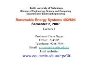
<strong>Curtin</strong> <strong>University</strong> of Technology<br />
Division of Engineering, Science and Computing<br />
Department of Electrical and Computer Engineering<br />
Power Electronics <strong>304</strong>/604<br />
Semester 2, 2008<br />
<strong>Lect</strong>ure 1<br />
Professor Chem Nayar<br />
Office: 204:205<br />
Telephone: 9266 7934<br />
Email: c.v.nayar@curtin.edu.au
Power Electronics <strong>304</strong>/604<br />
Tuition Pattern:<br />
5 Hours:<br />
<strong>Lect</strong>ure 2.00 hours, 1.00 weekly<br />
Tutorial 1.00 hour, 1.00 weekly<br />
Laboratory 2.00 hours, 1.00 weekly<br />
Assessment Details:<br />
Assignments : 40%<br />
Lab Report 1 (10%)<br />
Lab Report 2 (10%)<br />
Assignment (20%)<br />
Final Examination (3hours) : 60%<br />
(Closed Book Restricted Exam – 1 x A4 size paper<br />
with notes on both sides allowed).
Outline -- <strong>Lect</strong>ure 1<br />
• Introduction to Course Outline<br />
• Introduction to Power Electronics<br />
• Basic Concepts
What is Power Electronics?<br />
•Power electronics links the two major<br />
traditional divisions of electrical<br />
engineering, namely electrical power<br />
and electronics.<br />
•Involves the study of electronic circuits<br />
which control the flow of energy
Definition<br />
• Power electronics involves the study of<br />
electronic circuits intended to control the<br />
flow of electrical energy.<br />
• These circuits handle energy flow at levels<br />
much higher than individual device ratings.
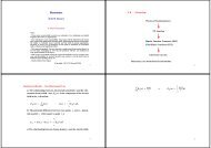
Power Electronic System<br />
The power electronics interface facilitates the transfer of power<br />
from the source to the load by converting voltages and currents<br />
from one form to another, in which it is possible<br />
for the source and load to reverse roles. The controller shown in<br />
Fig. 1-1 allows management of the power transfer process in<br />
which the conversion of voltages andcurrents should be<br />
achieved with as high energy-efficiency and high power density<br />
as possible.
Components of a power electronic system<br />
•Energy source<br />
•Temporary energy storage or filtering<br />
(inductance, capacitance)<br />
•Switch(es)<br />
•Load<br />
•Control hardware and software<br />
•Switch gate-drive circuitry
Introduction<br />
Power electronics encompasses three technologies: power semiconductor,<br />
power conversion, and power control.
Introduction<br />
• Electronics deals with the semiconductor devices and<br />
circuits used in signal processing to implement the<br />
control functions, power deals with both static and<br />
rotating equipment that uses electric power, and control<br />
deals with the steady-state stability of the closed-loop<br />
system during the power conversion process.<br />
• In power electronic circuits there exist two types of<br />
switching devices: one type in the power stage that<br />
handles high power up to hundreds of gigawatts (which<br />
represents the muscle of the system) and another type in<br />
the feedback control circuit that handles low power up to<br />
hundreds of milliwatts, representing the brain or<br />
intelligence of the system.
The Need For Power<br />
Conversion<br />
• The basis of utility power system generation, transmission, and<br />
distribution since the beginning of this century has been ac at a<br />
fixed frequency of either 50 or 60 Hz.<br />
• The most outstanding advantage of ac over dc is the<br />
maintenance of high voltage over long transmission lines and the<br />
simplicity of designing distribution networks.<br />
• At the consumer end many applications may need dc or ac power<br />
at line, higher, lower, or variable frequencies.<br />
• In some cases, the generated power is from dc sources such as<br />
batteries, fuel cells, or photovoltaic, and in other cases the<br />
available power is generated as variable-frequency ac from<br />
sources such as wind or gas turbines.<br />
• The need for this power conversion, ac-to-dc, became more<br />
acute with the invention of vacuum tubes, transistors, ICs, and<br />
computers.
• Compared with electromechanical systems and<br />
linear electronic systems, power electronics has<br />
many advantages, including<br />
– High energy conversion efficiency<br />
– Highly integrated power electronic systems<br />
– Reduced EMI and electronic pollution<br />
– Higher reliability<br />
– Use of environmentally clean voltage sources such as<br />
photovoltaic and fuel cells to generate electric power<br />
– The integration of electrical and mechanical systems<br />
– Maximum adaptability and controllability
Power Electronic Systems<br />
• Most power electronic systems consist of two major<br />
modules:<br />
– The power stage (forward circuit)<br />
– The control stage (feedback circuit)<br />
Simplified block diagram for a power electronic<br />
system<br />
x , x ,......, x<br />
1<br />
1<br />
1<br />
2<br />
y , y ,...... y<br />
p<br />
p<br />
in<br />
out<br />
2<br />
( t)<br />
( t)<br />
2<br />
m<br />
is the total instantaneous<br />
input power in watts<br />
f , f ,....., f<br />
is the total instantaneous<br />
output power in watts<br />
or angular<br />
Efficiency,<br />
η,<br />
is<br />
3<br />
n<br />
are input signals (voltage, current, or angular frequency)<br />
are output signals (voltages, currents, or<br />
are feedback signals : voltages or currents in an electricalsystem,<br />
speed or angular position in a mechanicalsystem.<br />
defined as follows :<br />
P<br />
η =<br />
P<br />
out<br />
in<br />
× 100%<br />
angular frequency)
Classification of Power<br />
Converter Circuits<br />
Detailed block diagram of a power electronic<br />
system<br />
• The function of the power<br />
converter stage is to perform the<br />
actual power conversion and<br />
processing of the energy from the<br />
input to the output by<br />
incorporating a matrix of power<br />
switching devices<br />
• Power conversion refers to the<br />
power electronic circuit that<br />
changes one of the following:<br />
– voltage form (ac or dc)<br />
– voltage level (magnitude)<br />
– voltage frequency (line or<br />
otherwise)<br />
– Voltage waveshape<br />
(sinusoidal or nonsinusoidal,<br />
such as square, triangle, or<br />
sawtooth),<br />
– Voltage phase (single-orthree-phase)
• There are four conversion circuits that are used in the majority of<br />
today’s power electronic circuits:<br />
– ac-to-ac<br />
– ac-to-dc<br />
– dc-to-ac<br />
– dc-to-dc<br />
• In terms of the functional description, modern power electronic<br />
systems perform one or more of the following conversion functions:<br />
– Rectification (ac-todc)<br />
– Inversion (dc-to-ac)<br />
– Cycloconversion (ac-to-ac, different frequencies) or ac<br />
controllers (ac-to-ac, same frequency)<br />
– Conversion (dc-to-dc)
Rectification (ac-to-dc)<br />
• The term rectification refers to the power circuit whose function is to<br />
alter the ac characteristic of the line electric power to produce a<br />
“rectified” ac power at the load site that contains the dc value.<br />
(a)<br />
ac-dc rectification (a) Simplified block diagram representation (b) Example of ac-dc<br />
conversion<br />
(b)
Inversion (dc-to-ac)<br />
• The term inversion is used to power electronic circuits for the<br />
function that alters the dc source (e.g. a battery) with no ac<br />
components into an “inverted” ac power at the load that has no dc<br />
components.<br />
(a) (b) (c)<br />
Dc-to-ac inversion (a) Simplified block diagram representation (b)<br />
Example of dc-ac inversion (c) Block diagram representation with<br />
high frequency inversion
Cycloconversion or Voltage<br />
Controllers (ac-to-ac)<br />
• The term cycloconversion is used for power electronic circuits that<br />
convert the ac input power at one frequency to an ac output power<br />
at a different frequency using one-stage conversion<br />
(a) (b) (c)<br />
Cycloconversion (a) One-stage ac-to-ac cycloconversion (b) Example of ac-to-ac<br />
conversion waveforms (c) Two-stage ac-to-ac cycloconversion
Conversion (dc-to-dc)<br />
• Dc-to-dc converters are used in power electronic circuits to convert<br />
an unregulated input dc voltage to a regulated or variable dc output<br />
voltage.<br />
(a) (b)<br />
Dc-to-dc conversion (a) One-stage dc-to-dc conversion (b) Example of<br />
waveforms (c) Two-stage dc-to-dc conversion<br />
(c)
Power electronic conversion system<br />
representing four possible conversion<br />
functions<br />
Simplified Block Diagram representation of the power electronic conversion<br />
function
• Load current io, and voltage vo, shown in figure below can be<br />
either positive or negative, there exist four modes of operation as<br />
show in (b)<br />
(a) (b)<br />
(a) Simple power electronic circuit with single voltage source and single load (b)<br />
Possible converter modes of operation
Power Semiconductor Devices<br />
• Because of the high conversion efficiency, semiconductor switching<br />
devices are considered the heart of power electronic circuits<br />
• Today, semiconductor switching devices have achieved<br />
unprecedented power-handling capabilities and switching speeds.<br />
• The devices include<br />
– Power diodes<br />
– Bipolar junction transistors (BJTs)<br />
– Metal oxide semiconductor field-effect transistors (MOSFETs)<br />
– Thyristors or silicon-controlled rectifiers such as triacs, diacs,<br />
gate turn-off (GTO) thyristors, static induction transistors (SITs),<br />
static induction thyristors (SITHs), and MOS-controlled thyristors<br />
(MCTs) are, in one way or another, from the same families of<br />
these five basic devices.
Applications of Power<br />
Electronics<br />
• Electrical applications<br />
– ac and dc regulated power supplies for various<br />
electronic equipment, including consumer electronics,<br />
instrumentation devices, computers, aerospace, and<br />
uninterruptible power supply (UPS) applications.<br />
• Electromechanical applications<br />
– used in industrial, residential, and commercial<br />
applications<br />
• Electrochemical applications<br />
– includes chemical processing, electroplating, welding,<br />
metal refining, production of chemical gases, and<br />
fluorescent lamp ballasts
Applications of Power Electronics by<br />
Conversion Functions (Partial List)<br />
Conversion Function Applications<br />
Uncontrolled ac-dc<br />
converters (diode<br />
circuits)<br />
Phase-controlled<br />
converters (thyristor<br />
circuits)<br />
Front-end off-line regulated dc-to-ac power supplies and<br />
dc-ac inverters<br />
Battery charges<br />
Welding<br />
Dc motor drives<br />
Regulated dc power supplies<br />
ac and dc variable-speed motor control<br />
Battery chargers<br />
Flexible ac transmission system (FACTS)<br />
Utility interface of photovoltaic systems<br />
Regulated ac inverters<br />
Solid-state circuit breakers<br />
Dc motor drives<br />
Induction heating<br />
Electromechanical processing (electroplating, anodizing,<br />
metal refining)<br />
HVDC systems<br />
Light dimmers<br />
Active power line conditioning (APLC)<br />
(var compensator, harmonic filters)<br />
Induction heating
Conversion Function Applications<br />
dc-dc converters<br />
High-frequency regulated dc power supplies<br />
using both isolated and nonisolated switchmode<br />
and soft-switching resonant<br />
topologies<br />
Digital and analog electronics<br />
Solar energy conversion<br />
High-frequency quasi-resonant converters<br />
Electric vehicles and trams<br />
dc-fed forklifts<br />
Fuel cell conversion<br />
dc traction drives<br />
Distributed power systems<br />
Power factor correction<br />
Solid-state relays<br />
Capacitor chargers
Conversion Function Applications<br />
Linear-mode dc-dc<br />
converters<br />
Cycloconverters<br />
and ac controllers<br />
(ac-ac)<br />
Low-power linear dc regulators<br />
Audio amplifiers<br />
RF amplifiers<br />
ac motor drives<br />
Rolling mill drives<br />
Static Scherbius drives<br />
Aircraft<br />
Frequency changers<br />
Solid-state power line conditioners<br />
Variable-speed constant-frequency (VSCF)<br />
systems<br />
Fluorescent lighting<br />
Light dimmers<br />
Induction heating
Conversion Function Applications<br />
dc-to-ac inverters<br />
Static switching<br />
Power ICs<br />
Aircraft and space power supply systems<br />
Ac variable-speed motor devices (lifts)<br />
Uninterruptible power supplies (UPS)<br />
Power factor correction<br />
Light dimmers<br />
Electric railroad systems<br />
Magnetically levitated (maglev) high-speed<br />
transportation systems<br />
Electric vehicles<br />
ac and dc circuit breakers<br />
Circuit protection<br />
Solid-state relays<br />
Home and office automation<br />
Automobiles<br />
Telecommunications<br />
ac and dc drives<br />
dc power supplies
Applications and the Role of Power<br />
Lighting 19%<br />
IT<br />
14%<br />
HVAC 16%<br />
Energy consumption in the US<br />
Electronics<br />
Motors 51%
Information and Communication
Electric Welding
Adjustable Speed Drives
Transportation<br />
Hybrid cars
Photovoltaic Power Systems<br />
(a)<br />
DC Input<br />
Power<br />
Electronics<br />
Interface<br />
(b)<br />
Utility
Wind Electric Systems<br />
Generator<br />
and<br />
Power Electronics<br />
Utility
Summarizing the Role of Power<br />
Electronics
Efficiency is critical
Devices available to Designers
Devices available to Designers
Devices available to Designers
Power loss in an ideal Switch
Example: DC-DC Converter
DC-DC Converter Example
DC-DC Converter : Linear Power Supply<br />
•Series transistor as an adjustable resistor<br />
•Low Efficiency<br />
•Heavy and bulky
DC-DC Converter : Use of a Single<br />
Pole Double Throw (SPDT)Switch
The switch changes the dc level
Addition of low pass filter
Addition of Control System : Switch<br />
mode Power supply
Switch-Mode Power Supply with<br />
• Transistor as a switch<br />
• High Efficiency<br />
• High-Frequency Transformer<br />
Isolation
Power Electronics <strong>304</strong>/604: The Syllabus<br />
• Applications and Structure of Switch-Mode<br />
Power Electronics<br />
• Simulation of power electronic circuits<br />
• Review of Magnetic Concepts<br />
• Diode Rectifiers and their Design<br />
• DC-DC Converters: Switching Details and<br />
their Average Dynamic Models<br />
• Design of High-Frequency Inductors
Recommended Texts and Principal References<br />
1. Ned Mohan, Tore M. Undeland and William P. Robbins, Power<br />
Electronics Converters, Applications, and Design, Second/third<br />
Edition, John Wiley, 2003 (TK7881.15.M64)<br />
2. Daniel W. Hart, Introduction to Power Electronics, Prentice Hall,<br />
1997 (TK7881.15.H37)<br />
3. John G. Kassakian, Martin F. Schlecht, and George C. Verghese,<br />
Principles of Power Electronics, Addison-Wesley, 1991<br />
(TK7881.15.K37).<br />
4. Philip T. Krein, Elements of Power Electronics, Oxford <strong>University</strong><br />
Press, 1998 (TK7881.15.K74)<br />
5. Muhammad H. Rashid, Power Electronics Circuits, Devices,<br />
and Applications, 3rd edition, Prentice-Hall, 2004<br />
(TK7881.15.R37)<br />
6. Issa Batarseh, Power Electronics Circuits, John Wiley, 2004
Week<br />
1<br />
2<br />
3<br />
4<br />
5<br />
6<br />
7<br />
8<br />
9<br />
10<br />
11<br />
12<br />
13<br />
Power Electronics <strong>304</strong>/604<br />
Day<br />
28-Jul<br />
4-Aug<br />
11-Aug<br />
18-Aug<br />
1-Sept<br />
8-Sept<br />
15-Sept<br />
22-Sept<br />
6-Oct<br />
13-Oct<br />
20-Oct<br />
27-Oct<br />
3-Nov<br />
Introduction<br />
DC-DC Converters 1<br />
DC-DC Converters 2<br />
DC-DC Converters 3<br />
DC-DC Converters 4<br />
Inductor Design<br />
Revision<br />
Fundamentals of<br />
Electric Circuit<br />
& Magnetics<br />
Overview of<br />
Semiconductor<br />
Switching<br />
Devices<br />
Rectifier Circuits 1<br />
Rectifier Circuits 2<br />
Rectifier Circuits 3<br />
Study week<br />
Pre-readings<br />
<strong>PE</strong> <strong>304</strong> Notes<br />
<strong>PE</strong> <strong>304</strong> Notes<br />
<strong>PE</strong> <strong>304</strong> Notes<br />
<strong>PE</strong> <strong>304</strong> Notes<br />
<strong>PE</strong> <strong>304</strong> Notes<br />
<strong>PE</strong> <strong>304</strong> Notes<br />
<strong>PE</strong> <strong>304</strong> Notes<br />
<strong>PE</strong> <strong>304</strong> Notes<br />
<strong>PE</strong> <strong>304</strong> Notes<br />
<strong>PE</strong> <strong>304</strong> Notes<br />
<strong>PE</strong> <strong>304</strong> Notes<br />
<strong>PE</strong> <strong>304</strong> Notes<br />
Tutorial<br />
Tutorial No.1<br />
Tutorial No.2<br />
Tutorial No.3<br />
Tutorial No.4<br />
Tutorial No.5<br />
Tutorial No.6<br />
Tutorial No.7<br />
Tutorial No.8<br />
Tutorial No.9<br />
Tutorial No.10<br />
Assignment Due<br />
Lab Report 1 (Group)<br />
Lab Report 2 (Group) +<br />
Assignment (<br />
individual)
Power Electronics Lab +Report & Assignments<br />
2 hour lab per week as a group – alternate between practical and computer lab<br />
Week 2 4/08/2008 Digital Osciloscope-Familirisation<br />
Week 3 11/08/2008 Single Phsse Rectifier<br />
Week 4 18/08/2008 Single Phsse Rectifier<br />
Week 5 25/08/2008 Tuition Free Week<br />
Week 6 1/09/2008 Three Phase Rectifier<br />
Week 7 8/09/2008 Three Phase Rectifier<br />
Week 8 15/09/2008 Catch Up Lab<br />
Week 9 22/09/2008 Buck Converter Report 1 ( Group)<br />
Week 10 29/09/2008 Tuition Free Week<br />
Week 11 6/10/2008 Buck Converter<br />
Week 12 13/10/2008 Boost Converter<br />
Week 13 20/10/2008 Boost Converter<br />
Week 14 27/10/2008 Buck-Boost Converter<br />
Week 15 3/11/2008 Study Week Report 2 ( Group )<br />
Assignment (individual)