PE304 – Tutorial #2 – Basic Electrical Theory - Curtin University
PE304 – Tutorial #2 – Basic Electrical Theory - Curtin University
PE304 – Tutorial #2 – Basic Electrical Theory - Curtin University

Create successful ePaper yourself
Turn your PDF publications into a flip-book with our unique Google optimized e-Paper software.
<strong>PE304</strong> <strong>–</strong> <strong>Tutorial</strong> <strong>#2</strong> Soln<br />
James Darbyshire & Professor Chem Nayar<br />
Faculty of Engineering and Computing<br />
Department of <strong>Electrical</strong> and Computer Engineering<br />
<strong>Curtin</strong> <strong>University</strong> of Technology<br />
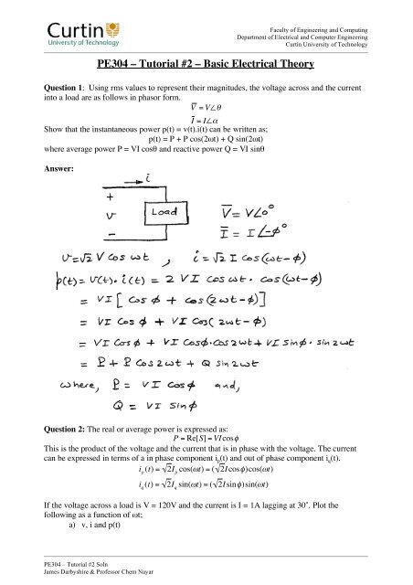
<strong>PE304</strong> <strong>–</strong> <strong>Tutorial</strong> <strong>#2</strong> <strong>–</strong> <strong>Basic</strong> <strong>Electrical</strong> <strong>Theory</strong><br />
Question 1: Using rms values to represent their magnitudes, the voltage across and the current<br />
into a load are as follows in phasor form.<br />
V = V<br />
I = I<br />
Show that the instantaneous power p(t) = v(t).i(t) can be written as;<br />
p(t) = P + P cos(2t) + Q sin(2t)<br />
where average power P = VI cos and reactive power Q = VI sin<br />
Answer:<br />
Question 2: The real or average power is expressed as:<br />
P = Re[S] = VI cos<br />
This is the product of the voltage and the current that is in phase with the voltage. The current<br />
can be expressed in terms of a in phase component i p(t) and out of phase component i q(t).<br />
i p (t) = 2I p cos(t) = ( 2I cos)cos(t)<br />
i q (t) = 2I q sin(t) = ( 2I sin)sin(t)<br />
If the voltage across a load is V = 120V and the current is I = 1A lagging at 30˚. Plot the<br />
following as a function of t;<br />
a) v, i and p(t)
<strong>Tutorial</strong> <strong>#2</strong> Solution 2 of 2<br />
b) i p(t) as defined above and p 1(t) = v.i p<br />
c) i q(t) as defined above and p 2(t) = v.i q<br />
d) Calculate the average power P<br />
e) Calculate the peak power of p 2 and Q.<br />
f) Calculate the load power factor (PF). Is this load inductive or capacitive? Does the<br />
load draw positive vars?<br />
Answer:<br />
a)<br />
b)<br />
c)<br />
d/e/f)<br />
James Darbyshire & Professor Chem Nayar
<strong>Tutorial</strong> <strong>#2</strong> Solution 3 of 3<br />
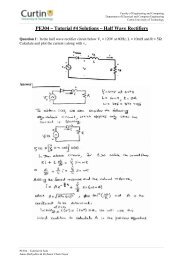
Question 3: A sinusoidal voltage v = 2V sin t is applied to a single phase load. The current<br />
drawn by the load corresponds to figure 1. The zero crossing of the current waveform lags the<br />
voltage waveform by 30˚. Calculate the average power drawn by the load. The displacement<br />
power factor (DPF), the total harmonic distortion, and the power factor.<br />
Where V = 120V, A = 10A.<br />
Figure 1<br />
Answer:<br />
The expansion of the Fourier series for the above waveform is given by:<br />
The ratio of the fundamental component to the rms is given by:<br />
James Darbyshire & Professor Chem Nayar
<strong>Tutorial</strong> <strong>#2</strong> Solution 4 of 4<br />
Question 4: A three phase inductive load is supplied in steady state by a balanced three phase<br />
voltage source with a phase voltage of 120Vrms. The load draws a total of 10kW at a power<br />
factor of 0.85 (lagging). Calculate the rms values of the phase currents and the magnitude of the<br />
per-phase load impedance. Draw a phasor diagram showing all three voltages and currents.<br />
Answer:<br />
James Darbyshire & Professor Chem Nayar