- Page 2:
Clean-In-Place for Biopharmaceutica
- Page 13 and 14:
Informa Healthcare USA, Inc. 52 Van
- Page 15 and 16:
iv Preface period, the industry rec
- Page 18 and 19:
Preface iii Contents Acknowledgment
- Page 20:
Contributors Barry J. Andersen Seib
- Page 23 and 24:
2 the last step of abatch manufactu
- Page 25 and 26:
4 Seiberling The vessel capacity ma
- Page 27 and 28:
6 Seiberling any two ports. For pur
- Page 29 and 30:
8 AWFI (or Any Water) Supply If the
- Page 31 and 32:
10 Seiberling program, and through
- Page 33 and 34:
12 Seiberling (380 L) for the solut
- Page 35 and 36:
14 AWFI CIP skid Drain When steam a
- Page 37 and 38:
16 Seiberling products in asingle f
- Page 39 and 40:
18 Seiberling The literature began
- Page 42 and 43:
2 Project Planning for the CIPable
- Page 44 and 45:
Project Planning for CIPable Facili
- Page 46 and 47:
Project Planning for CIPable Facili
- Page 48 and 49:
Project Planning for CIPable Facili
- Page 50 and 51:
Project Planning for CIPable Facili
- Page 52 and 53:
Project Planning for CIPable Facili
- Page 54 and 55:
Project Planning for CIPable Facili
- Page 56 and 57:
Project Planning for CIPable Facili
- Page 58 and 59:
Project Planning for CIPable Facili
- Page 60 and 61:
Project Planning for CIPable Facili
- Page 62 and 63:
3 Water for the CIP System Jay C. A
- Page 64 and 65:
Water for the CIP System 43 FIGURE
- Page 66 and 67:
Water for the CIP System 45 of clea
- Page 68 and 69:
Water for the CIP System 47 FIGURE
- Page 70 and 71:
Water for the CIP System 49 FIGURE
- Page 72:
Water for the CIP System 51 WATER U
- Page 75 and 76:
54 Time Temperature FIGURE 2 The cl
- Page 77 and 78:
56 Classification of Cleaners by pH
- Page 79 and 80:
58 [mg/sec] Cleaning velocity C v ,
- Page 81 and 82:
60 + - Na O O C CH 2 CH 2 (CH 2 ) n
- Page 83 and 84:
62 CH3 -(CH2 ) n -CH2 -O -CH2 -CH2
- Page 85 and 86:
64 B C D E FIGURE 17 Capability of
- Page 87 and 88:
66 pH 13 pH 7 pH, %, Excess water h
- Page 89 and 90:
68 dramatically increased rinsing t
- Page 91 and 92:
70 desorption. If the affinity is v
- Page 93 and 94:
72 & Cleaning procedure inthe case
- Page 95 and 96:
74 effort being performed relativel
- Page 97 and 98:
76 Rush & A1000 Lmixing vessel, hav
- Page 99 and 100:
78 TABLE 2 Typical Single-Pass Chem
- Page 101 and 102:
80 Rush Rinse Volume (Duration) The
- Page 103 and 104:
82 Rush Intermediate Drain Objectiv
- Page 105 and 106:
84 Rush Final Drain Phase (Gravity)
- Page 107 and 108:
86 TABLE 4 Recirculated Chemical Wa
- Page 109 and 110:
88 Rush type of soil include fermen
- Page 111 and 112:
90 The pre-cleaning process flush w
- Page 113 and 114:
92 REFERENCES Rush 1. Howard T, Wie
- Page 115 and 116:
94 CIP return (CIPR)-piping to conv
- Page 117 and 118:
96 Seiberling provided, generally o
- Page 119 and 120:
98 Single-Tank CIP Skid Operational
- Page 121 and 122:
100 Single-Tank Bypass or Recycle O
- Page 123 and 124: 102 Seiberling Single-Tank Single P
- Page 125 and 126: 104 Seiberling installation of an e
- Page 127 and 128: 106 Chemical loop AB FE Chemical bl
- Page 129 and 130: 108 Chemical loop AB FCV FE Steam C
- Page 131 and 132: CIP supply Transfer line (typical)
- Page 133 and 134: 112 Seiberling FIGURE 14 This singl
- Page 135 and 136: 114 Seiberling FIGURE 15 This large
- Page 137 and 138: 116 Seiberling FIGURE 17 This mini-
- Page 140 and 141: 7 CIP System Instrumentation and Co
- Page 142 and 143: CIP System Instrumentation and Cont
- Page 144 and 145: CIP System Instrumentation and Cont
- Page 146 and 147: CIP System Instrumentation and Cont
- Page 148 and 149: CIP System Instrumentation and Cont
- Page 150 and 151: CIP System Instrumentation and Cont
- Page 152 and 153: CIP System Instrumentation and Cont
- Page 154 and 155: CIP System Instrumentation and Cont
- Page 156 and 157: CIP System Instrumentation and Cont
- Page 158 and 159: CIP System Instrumentation and Cont
- Page 160 and 161: CIP System Instrumentation and Cont
- Page 162 and 163: CIP System Instrumentation and Cont
- Page 164: CIP System Instrumentation and Cont
- Page 167 and 168: 146 Lebowitz should be considered f
- Page 169 and 170: 148 Lebowitz barrels and the chemic
- Page 171 and 172: 150 Lebowitz Electromagnetic-Operat
- Page 173: 152 Lebowitz FIGURE 5 The venturi o
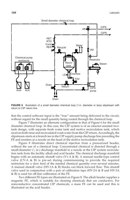
- Page 177 and 178: 156 Steam Facility acid header Faci
- Page 179 and 180: 158 Lebowitz That is to say aweak a
- Page 181 and 182: 160 CIP Philosophy The production p
- Page 183 and 184: 162 Franks and Seiberling the numbe
- Page 185 and 186: 164 Franks and Seiberling Similar s
- Page 187 and 188: 166 Franks and Seiberling FIGURE 3
- Page 189 and 190: 168 Franks and Seiberling FIGURE 5
- Page 191 and 192: 170 (A) (B) Franks and Seiberling F
- Page 193 and 194: 172 Franks and Seiberling FIGURE 9
- Page 195 and 196: 174 The variables that impact the r
- Page 197 and 198: 176 There are two guiding concepts
- Page 199 and 200: 178 Mezz. Floor(ref.) V-5 1000L CIP
- Page 201 and 202: 180 return line piping, substantial
- Page 203 and 204: 182 Lebowitz U-bend transfer panels
- Page 205 and 206: 184 Lebowitz oriented vertically. T
- Page 207 and 208: 186 Lebowitz suction-side port on T
- Page 209 and 210: CIPS loop Primary CIPS CIPSPS CIPS
- Page 211 and 212: 190 Lebowitz FIGURE 10 Photo of sma
- Page 213 and 214: 192 Drain CIP return Drain Recycle
- Page 216 and 217: 11 Materials of Construction and Su
- Page 218 and 219: Materials of Construction and Surfa
- Page 220 and 221: Materials of Construction and Surfa
- Page 222 and 223: Materials of Construction and Surfa
- Page 224 and 225:
Materials of Construction and Surfa
- Page 226 and 227:
Materials of Construction and Surfa
- Page 228 and 229:
Materials of Construction and Surfa
- Page 230 and 231:
Materials of Construction and Surfa
- Page 232 and 233:
12 Cleanable In-Line Components INT
- Page 234 and 235:
Cleanable In-Line Components 213 &
- Page 236 and 237:
Cleanable In-Line Components 215 Al
- Page 238 and 239:
Cleanable In-Line Components 217 Ex
- Page 240 and 241:
Cleanable In-Line Components 219 FI
- Page 242 and 243:
Cleanable In-Line Components 221 Tr
- Page 244 and 245:
Cleanable In-Line Components 223 it
- Page 246 and 247:
Cleanable In-Line Components 225 FI
- Page 248 and 249:
Cleanable In-Line Components 227 FI
- Page 250 and 251:
Cleanable In-Line Components 229 eq
- Page 252 and 253:
Cleanable In-Line Components 231 Th
- Page 254 and 255:
Cleanable In-Line Components 233 co
- Page 256 and 257:
13 Cleanable Liquids Processing Equ
- Page 258 and 259:
Cleanable Liquids Processing Equipm
- Page 260 and 261:
Cleanable Liquids Processing Equipm
- Page 262 and 263:
Cleanable Liquids Processing Equipm
- Page 264 and 265:
Cleanable Liquids Processing Equipm
- Page 266 and 267:
Cleanable Liquids Processing Equipm
- Page 268 and 269:
1-9 CIPS 2 Plant steam CIPS valves
- Page 270 and 271:
Cleanable Liquids Processing Equipm
- Page 272 and 273:
Cleanable Liquids Processing Equipm
- Page 274 and 275:
Cleanable Liquids Processing Equipm
- Page 276:
Cleanable Liquids Processing Equipm
- Page 279 and 280:
258 8. Projectile-type thermometer
- Page 281 and 282:
260 Forder control of the drying pr
- Page 283 and 284:
262 Forder FIGURE 5 Pharmaceutical
- Page 285 and 286:
264 Forder FIGURE 7 Pharmaceutical
- Page 287 and 288:
266 FIGURE 9 Pleated filter cartrid
- Page 289 and 290:
268 FIGURE 12 Disassembledstainless
- Page 291 and 292:
270 The acid wash of 85% phosphoric
- Page 293 and 294:
272 FIGURE 17 Sanitary Vbenders. So
- Page 295 and 296:
274 one each for the upper, central
- Page 297 and 298:
276 CIP VS. TRADITIONAL BOIL-UP MET
- Page 299 and 300:
278 Cerulli were not designed to be
- Page 301 and 302:
280 by large flanged connections fo
- Page 303 and 304:
282 CIP header Once thru CIP soluti
- Page 305 and 306:
284 Nozzle Use A Manway B Agitator
- Page 307 and 308:
286 3" Stub end w/150# flange 2A 1
- Page 309 and 310:
288 In most cases, the pressure dro
- Page 311 and 312:
290 CIP fluids Process fluids 1 2 3
- Page 313 and 314:
292 A Vent to atm. B M Conical drye
- Page 315 and 316:
294 One of the designer’s first t
- Page 318 and 319:
16 CIP System Troubleshooting Guide
- Page 320 and 321:
CIP System Troubleshooting Guide 29
- Page 322 and 323:
CIP System Troubleshooting Guide 30
- Page 324 and 325:
CIP System Troubleshooting Guide 30
- Page 326 and 327:
CIP System Troubleshooting Guide 30
- Page 328 and 329:
CIP System Troubleshooting Guide 30
- Page 330 and 331:
CIP System Troubleshooting Guide 30
- Page 332 and 333:
CIP System Troubleshooting Guide 31
- Page 334 and 335:
CIP System Troubleshooting Guide 31
- Page 336 and 337:
17 Waste Treatment for the CIP Syst
- Page 338 and 339:
Waste Treatment for the CIP System
- Page 340 and 341:
Waste Treatment for the CIP System
- Page 342 and 343:
Waste Treatment for the CIP System
- Page 344 and 345:
Waste Treatment for the CIP System
- Page 346 and 347:
Waste Treatment for the CIP System
- Page 348 and 349:
18 Commissioning and Qualification
- Page 350 and 351:
Commissioning and Qualification 329
- Page 352 and 353:
Commissioning and Qualification 331
- Page 354 and 355:
Commissioning and Qualification 333
- Page 356 and 357:
Commissioning and Qualification 335
- Page 358 and 359:
Commissioning and Qualification 337
- Page 360 and 361:
Commissioning and Qualification 339
- Page 362 and 363:
Commissioning and Qualification 341
- Page 364 and 365:
Commissioning and Qualification 343
- Page 366:
Commissioning and Qualification 345
- Page 369 and 370:
348 & Sterilization refers to the r
- Page 371 and 372:
350 Lankford All analytical methods
- Page 373 and 374:
352 should be based upon scientific
- Page 375 and 376:
354 Lankford acleaning validation p
- Page 377 and 378:
356 In summary, TOC analysis is are
- Page 379 and 380:
358 In-Situ In-situ measurement tec
- Page 381 and 382:
360 15. Karen A. Clark, Product Man
- Page 383 and 384:
362 Actually, most countries revise
- Page 385 and 386:
364 §211.100 Written procedures; d
- Page 387 and 388:
366 §211.186 Master production and
- Page 389 and 390:
368 Equipment Regulation C.02.005 T
- Page 391 and 392:
370 … C.02.004 … 4. Pipework sy
- Page 393 and 394:
372 5.20 Schedules and procedures (
- Page 395 and 396:
374 TABLE 1 Directives of the Europ
- Page 397 and 398:
376 TABLE 5 Cleanability Performanc
- Page 400 and 401:
Index Accessibility, 28 Acid cleane
- Page 402 and 403:
Index 381 CIP supply flow troublesh
- Page 404 and 405:
Index 383 [Cleaning cycle sequences
- Page 406 and 407:
Index 385 Flow alarm, no-return, 30
- Page 408 and 409:
Index 387 Off skid instrumentation,
- Page 410 and 411:
Index 389 Rising stem valves, 223-2
- Page 412:
Index 391 [Troubleshooting] spray c