Create successful ePaper yourself
Turn your PDF publications into a flip-book with our unique Google optimized e-Paper software.
<strong>USER</strong> <strong>GUIDE</strong><br />
Publication AP6388<br />
Allen & Heath 1 <strong>XONE</strong>:<strong>3D</strong> User Guide
Limited One Year Warranty<br />
This product is warranted to be free from defects in materials or<br />
workmanship for period of one year from the date of purchase by the<br />
original owner.<br />
To ensure a high level of performance and reliability for which this<br />
equipment has been designed and manufactured, read this User Guide<br />
before operating. In the event of a failure, notify and return the<br />
defective unit to ALLEN & HEATH Limited or its authorised agent as<br />
soon as possible for repair under warranty subject to the following<br />
conditions<br />
Conditions Of Warranty<br />
The equipment has been installed and operated in accordance with the<br />
instructions in this User Guide.<br />
The equipment has not been subject to misuse either intended or<br />
accidental, neglect, or alteration other than as described in the User<br />
Guide or Service Manual, or approved by ALLEN & HEATH.<br />
Any necessary adjustment, alteration or repair has been carried out by<br />
ALLEN & HEATH or its authorised agent.<br />
This warranty does not cover fader wear and tear.<br />
The defective unit is to be returned carriage prepaid to ALLEN &<br />
HEATH or its authorised agent with proof of purchase.<br />
Units returned should be packed to avoid transit damage.<br />
In certain territories the terms may vary. Check with your ALLEN &<br />
HEATH agent for any additional warranty which may apply.<br />
This product complies with the European Electro magnetic<br />
Compatibility directives 89/336/EEC & 92/31/EEC and the<br />
European Low Voltage Directives 73/23/EEC & 93/68/EEC.<br />
This product has been tested to EN55103 Parts 1 & 2 1996 for use in<br />
Environments E1, E2, E3, and E4 to demonstrate compliance with the<br />
protection requirements in the European EMC directive 89/336/EEC.<br />
During some tests the specified performance figures of the product were<br />
affected. This is considered permissible and the product has been passed as<br />
acceptable for its intended use. Allen & Heath has a strict policy of<br />
ensuring all products are tested to the latest safety and EMC standards.<br />
Customers requiring more information about EMC and safety issues can<br />
contact Allen & Heath.<br />
<strong>XONE</strong>:<strong>3D</strong> User Guide AP6388 Issue 1<br />
Copyright © 2006 Allen & Heath Limited. All rights reserved<br />
Allen & Heath Limited<br />
Kernick Industrial Estate, Penryn, Cornwall, TR10 9LU, UK<br />
http://www.allen-heath.com http://www.xone.co.uk<br />
Allen & Heath 2 <strong>XONE</strong>:<strong>3D</strong> User Guide
SOFTWARE INSTALLATION<br />
STOP!<br />
BEFORE YOU DO ANYTHING WITH YOUR <strong>XONE</strong>:<strong>3D</strong>, PLEASE READ THE<br />
FOLLOWING CAREFULLY TO ENSURE YOUR PC IS CORRECTLY SET UP TO<br />
BE USED WITH THE MIXER.<br />
Software Installation (Windows 2000 and XP)<br />
Follow the procedure described below to install the USB audio and MIDI drivers:<br />
1— Connect the Xone:<strong>3D</strong> to your mains electricity supply and switch it on.<br />
Do not connect the <strong>3D</strong> to the PC at this time.<br />
2— Insert the Xone:<strong>3D</strong> Utility Disk, and run DRIVERS setup.<br />
4— Select your preferred language<br />
6— You will also be asked to unplug and<br />
re-plug during the installation.<br />
7— The driver installation will complete<br />
without reboot (XP) or ask you to reboot<br />
your PC (2000).<br />
When the driver installation is complete,<br />
go back to the Utility Disk main menu and<br />
copy the CONFIG UTILITY to your<br />
desktop. Run this program when you are<br />
ready to configure the soundcard<br />
operating mode, its inputs and outputs,<br />
change the MIDI settings, or update the<br />
Xone:<strong>3D</strong> firmware.<br />
3— Select “Install the driver”<br />
5— When prompted, connect the <strong>3D</strong> to<br />
the PC with the USB lead.<br />
Note: Always use the same USB port<br />
with your Xone:<strong>3D</strong>. When installing on a<br />
MS Windows system, the drivers will be<br />
associated with the USB port that you are<br />
currently plugged into. If you attempt to use<br />
the <strong>3D</strong> with another USB port, or without<br />
installing the drivers at all, the system may<br />
work but with degraded performance (XP),<br />
or may not work at all (2000).
Check that you have received the following:<br />
Mains Lead<br />
Check that the correct<br />
mains plug is fitted.<br />
PACKED ITEMS<br />
Xone:<strong>3D</strong> mixer<br />
Check that the rear panel optical in/out blank plugs are fitted.<br />
Type A-B USB Lead<br />
To connect the Xone:<strong>3D</strong><br />
to your computer.<br />
2x pairs of Overlay Sheets<br />
To identify MIDI control<br />
functions for popular DJ<br />
software:<br />
Ableton Live5 Lite and<br />
Native Instruments<br />
Traktor<br />
Spare knobs<br />
and buttons<br />
Xone:<strong>3D</strong> Utility CD including:<br />
This user guide, ASIO drivers,<br />
Configuration Utility software,<br />
Ableton Live Lite 5 application.<br />
Ableton Live Lite 5 Postcard<br />
Includes software serial number<br />
and information for upgrade.<br />
Safety Sheet<br />
Important ! Read this sheet<br />
before starting.<br />
Retain for future reference.<br />
Registration Card<br />
Complete and return<br />
to Allen & Heath to<br />
register your product.<br />
Rack Ears + fixings.<br />
For mounting the <strong>3D</strong><br />
in a 19” rack.<br />
6x M4x10mm screws<br />
Allen & Heath 4 <strong>XONE</strong>:<strong>3D</strong> User Guide
CONTENTS<br />
Congratulations on purchasing the Allen & Heath Xone:<strong>3D</strong><br />
performance DJ mixer. To ensure that you get the<br />
maximum benefit from the unit please spare a few minutes<br />
familiarizing yourself with the controls and setup procedures<br />
outlined in this user guide. For further information please<br />
refer to the additional information available on our web site,<br />
or contact our technical support team.<br />
http://www.xone.co.uk<br />
http://www.allen-heath.com<br />
Warranty .............................................. 2<br />
Software Installation........................... 3<br />
Packed Items........................................ 4<br />
Panel Drawings.................................... 6<br />
Introduction ......................................... 7<br />
Description .......................................... 8<br />
Soundcard Operating Modes........... 10<br />
Channel Input ...................................... 12<br />
Mix and Monitor................................. 14<br />
Filters and LFO.................................... 15<br />
FX Returns and Crossfader ............. 16<br />
Front Controls and Connectors..... 17<br />
Rear Connectors ................................ 18<br />
BPM Counter....................................... 21<br />
LFO ........................................................ 23<br />
MIDI Control Section........................ 24<br />
MIDI Implementation Chart............. 26<br />
MIDI Note Chart................................ 27<br />
Filter Reference................................... 28<br />
Operating levels .................................. 29<br />
Earthing................................................. 30<br />
Cables and Connectors..................... 31<br />
User Options....................................... 32<br />
Replacing the Crossfader.................. 35<br />
FAQs...................................................... 36<br />
Mixer Troubleshooting....................... 37<br />
Soundcard and MIDI Troubleshooting 38<br />
Updating Firmware............................. 40<br />
Specifications ...................................... 42<br />
Allen & Heath 5 <strong>XONE</strong>:<strong>3D</strong> User Guide
WARNING: FOR CONTINUED PROTECTION AGAINST RISK OF FIRE<br />
REPLACE FUSE WITH SAME TYPE AND RATING.<br />
ATTENTION: REMPLACER LE FUSIBLE AVEC<br />
UN DES MEMES CARACTERISTIQUES.<br />
WARNING: THIS APPARATUS MUST BE EARTHED.<br />
TO REDUCE THE RISK OF FIRE OR ELECTRIC SHOCK<br />
DO NOT EXPOSE APPARATUS TO RAIN OR MOISTURE.<br />
SERIAL No:<br />
0<br />
I<br />
CAUTION<br />
OFF<br />
ON<br />
A B C<br />
E F<br />
JOG / SELECT<br />
I J<br />
AC MAINS IN ~<br />
100 - 240V~<br />
G<br />
K<br />
T500mAL 250V 20mm<br />
FUSE<br />
47-63Hz ~ 30W MAX MADE IN THE UK BY ALLEN & HEATH LIMITED<br />
D<br />
H<br />
L<br />
MIX OUT<br />
LEFT RIGHT<br />
MODE<br />
MIDI<br />
MIDI CH<br />
+10!<br />
+6<br />
+3<br />
0<br />
START<br />
-3<br />
STOP<br />
RESET<br />
FX1<br />
FX1<br />
FX1<br />
FX1<br />
-6<br />
-10<br />
PULL<br />
CLOCK<br />
+<br />
PUSH<br />
00<br />
+6<br />
PRE<br />
00 +6<br />
PRE<br />
00 +6<br />
PRE<br />
00 +6<br />
PRE<br />
-15<br />
-20<br />
L<br />
R<br />
TAP FX2<br />
FX2<br />
FX2<br />
FX2<br />
4<br />
5<br />
6<br />
3<br />
7<br />
MIX<br />
OFF<br />
AUTO BPM<br />
SELECT<br />
FX2<br />
00<br />
+6<br />
LINE A<br />
LINE B<br />
SC 1 - 2<br />
00 +6<br />
PHONO<br />
LINE<br />
SC 3 - 4<br />
00 +6<br />
PHONO<br />
LINE<br />
SC 5 - 6<br />
00 +6<br />
PHONO<br />
LINE<br />
SC 1 - 2<br />
2<br />
8<br />
1<br />
9<br />
0 10<br />
MIX<br />
4<br />
5<br />
6<br />
3<br />
7<br />
2<br />
8 FX1<br />
LEVEL<br />
LEVEL<br />
LEVEL<br />
LEVEL<br />
4<br />
5<br />
3<br />
2<br />
6<br />
7<br />
8<br />
1<br />
0<br />
9 RTN<br />
10<br />
-10 +10<br />
-10 +10<br />
-10 +10<br />
-10 +10<br />
1<br />
0<br />
9<br />
10<br />
5<br />
4 6<br />
HF<br />
HF<br />
HF<br />
HF<br />
MONITOR<br />
3<br />
2<br />
1<br />
7<br />
8 FX2<br />
9 RTN<br />
CUE ACTIVE<br />
0 10<br />
OFF +6<br />
OFF +6<br />
OFF +6<br />
OFF +6<br />
FX 1<br />
LFO MF<br />
MF<br />
MF<br />
MF<br />
TAP<br />
TEMPO<br />
4<br />
5<br />
6<br />
3<br />
7<br />
OFF<br />
LF<br />
+6<br />
OFF<br />
LF<br />
+6<br />
OFF<br />
LF<br />
+6<br />
OFF<br />
LF<br />
+6<br />
2<br />
8<br />
1<br />
9<br />
0 10<br />
DEPTH<br />
1 2 OFF +6<br />
OFF +6<br />
OFF +6<br />
OFF +6<br />
1+2 ASSIGN<br />
FILTER<br />
FILTER<br />
FILTER<br />
FILTER<br />
XFADE<br />
XFADE<br />
XFADE<br />
XFADE<br />
XFADE<br />
1X<br />
Y 2 1X<br />
Y 2 1X<br />
Y 2 1X Y 2<br />
ON<br />
OFF<br />
OFF<br />
OFF<br />
OFF<br />
RES<br />
MILD<br />
20Hz<br />
BPM<br />
FILTER 1 ON<br />
WILD<br />
HPF<br />
BPF<br />
LPF<br />
FREQ<br />
20kHz<br />
CUE<br />
+10! +10!<br />
+6<br />
+3<br />
0<br />
-3<br />
-6<br />
-10<br />
-15<br />
-20<br />
INPUT 4<br />
PHONO L R<br />
OO<br />
XFADE CURVE<br />
1<br />
PHONO L R<br />
ALLEN&HEATH<br />
CUE<br />
+6<br />
+3<br />
0<br />
-3<br />
-6<br />
-10<br />
-15<br />
-20<br />
PHONO L R<br />
CUE<br />
2 3<br />
+10!<br />
+6<br />
+3<br />
0<br />
-3<br />
-6<br />
-10<br />
-15<br />
-20<br />
OO OO<br />
Allen & Heath 6 <strong>XONE</strong>:<strong>3D</strong> User Guide<br />
FX2 SEND<br />
LINE<br />
A<br />
CUE<br />
+10!<br />
+6<br />
+3<br />
0<br />
-3<br />
-6<br />
-10<br />
-15<br />
-20<br />
L R<br />
X Y<br />
OO<br />
4<br />
FX RETURNS<br />
FX1 L R<br />
LINE L R LINE L R LINE L R LINE<br />
B<br />
L R FX2 L R<br />
L<br />
R<br />
INPUT 3<br />
MONITOR<br />
L<br />
R<br />
FX1 SEND<br />
INPUT 2<br />
L<br />
R<br />
CH1<br />
L<br />
CH2<br />
R<br />
INPUT 1<br />
SOUNDCARD OUTPUTS<br />
CH3<br />
L<br />
CH4<br />
R<br />
PHONES<br />
RES<br />
FILTER 2 ON<br />
FX 2<br />
CUE ADD MIX<br />
5 6<br />
4<br />
7<br />
3<br />
8<br />
2<br />
9 LEVEL<br />
1<br />
10<br />
0 11<br />
MILD<br />
20Hz<br />
CH5<br />
L<br />
CH6<br />
R<br />
WILD<br />
HPF<br />
BPF<br />
LPF<br />
FREQ<br />
20kHz<br />
IN<br />
OUT<br />
SPDIF<br />
M N<br />
O P<br />
Q<br />
U<br />
JOG / SELECT<br />
PHONES<br />
DIGITAL AUDIO<br />
OPTICAL<br />
IN OUT<br />
R<br />
V<br />
LF<br />
GAME/MIDI<br />
HF<br />
IN<br />
S<br />
W<br />
MIDI<br />
OUT<br />
-12 +12 -12 +12 0<br />
MIC<br />
T<br />
X<br />
USB<br />
TO PC<br />
LEVEL<br />
FOOT<br />
SWITCH<br />
10
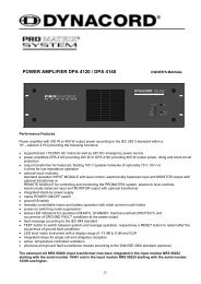
INTRODUCTION TO THE <strong>XONE</strong>:<strong>3D</strong><br />
Welcome to the Allen & Heath Xone:<strong>3D</strong> digital DJ workstation. This system has<br />
been designed with the help of some of the world’s most cutting edge DJs to<br />
provide a seamless integration of traditional and computer based audio replay<br />
systems. The Xone:<strong>3D</strong> comprises three main sections:<br />
MIXER— The mixer is based on the award winning Allen & Heath Xone:92. It<br />
lets you mix a combination of vinyl, CD and other sources through 4 stereo<br />
channels to its main mix and monitor outputs. It provides 2 effects send/return<br />
loops, 3-band EQ isolators, 2 analogue VCF filters with LFO, VCA crossfader and<br />
channel faders, DJ mic and cue monitoring system. A BPM counter can be set for<br />
tap tempo or automatic beat detection.<br />
MIDI CONTROLLER— Two dedicated control strips provide a total of 105<br />
MIDI messages from a combination of switches, rotary and fader controls, multifunction<br />
jog wheels, foot pedal and game controllers. In addition, several mixer<br />
functions generate and respond to MIDI, and the BPM counter provides MIDI<br />
start/stop and clock. The Xone:<strong>3D</strong> provides full control of external MIDI devices<br />
including the most sophisticated DJ performance computer environments.<br />
Overlays are available to identify the control function for popular software<br />
applications.<br />
SOUNDCARD— A high performance 8 channel USB soundcard is built into the<br />
mixer. This is arranged as 4 stereo signals which may be configured as either<br />
1in/3out or 2in/2out. It uses USB to interface the mixer audio and MIDI to a PC<br />
where the sound may be manipulated in real time using one of the several exciting<br />
new DJ performance programs. The soundcard also produces SPDIF coax and<br />
optical digital inputs and outputs. A PC utility program is used to configure the<br />
soundcard operating mode, its digital signal sources and MIDI parameters. A low<br />
latency ASIO driver is provided for audio streaming between mixer and PC.<br />
SOUNDCARD<br />
MIDI BPM MIXER<br />
MIDI<br />
LFO<br />
CROSSFADER<br />
FILTER 1 FILTER 2<br />
PHONES<br />
FX1<br />
FX2<br />
EQ<br />
CUE<br />
CH1 CH2 CH3 CH4<br />
Allen & Heath 7 <strong>XONE</strong>:<strong>3D</strong> User Guide<br />
MIC<br />
MASTER<br />
MONITOR
MODE 1<br />
USB<br />
AUDIO IN/OUT<br />
MIDI CONTROL<br />
COMPUTER<br />
GAME/MIDI<br />
1 STEREO IN / 3 STEREO OUT<br />
SOUNDCARD OUT<br />
5 3 1<br />
6 4 2<br />
DAC<br />
DAC<br />
MIDI IN<br />
FOOTSWITCH<br />
DAC<br />
SOUNDCARD IN<br />
OPTICAL<br />
COAX<br />
CONFIGURATION<br />
MIDI OUT<br />
SC 1-2<br />
OUT SPDIF IN<br />
OPTICAL COAX OPTICAL COAX<br />
DIGITAL OUT<br />
ADC<br />
ADC<br />
SOUNDCARD<br />
MIX<br />
FX1<br />
CH3 PHONO<br />
MIX<br />
FX1<br />
CH2 PHONO<br />
MIDI CONTROL<br />
MIDI TO USB<br />
MIDI OUT<br />
MIDI OUT<br />
MIDI IN<br />
CV IN<br />
CV IN<br />
MAP1<br />
MAP2<br />
MIDI CLOCK<br />
MAPPING<br />
LEFT BANK<br />
RIGHT BANK<br />
MIXER<br />
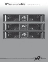
DESCRIPTION<br />
The diagram below shows the signal flow through the Xone:<strong>3D</strong> system.<br />
MIXER— Each of the 4 channels can select one of 3 sources: phono, line or<br />
soundcard audio as shown. RIAA phono preamps are available on channels 2, 3<br />
and 4. These may be changed to line input by resetting an internal jumper link if<br />
required. Level may be adjusted over a +/- 10dB range if the signal reads too high<br />
or low on the channel meters. The 3-band EQ provides a safe amount of boost<br />
but full cut (kill) for dramatic effect. A mic input with level and 2-band EQ routes<br />
direct to the main mix. The DJ cues the mix using headphones. The mix may be<br />
added to the cue’d channel signal to help the DJ synchronise the beat.<br />
FILTERS— The channel signal may be routed direct to the LR mix or through<br />
either of the two analogue filters. These provide the characteristic Allen & Heath<br />
analogue filter sound with combinations of 3 switched bands, swept frequency,<br />
resonance and tap tempo LFO control. The VCA crossfader affects the filter path<br />
when switched in.<br />
FX LOOPS— Two FX sends are provided. FX1 may be switched pre or post<br />
fader. FX2 is pre fader. The send is typically connected to an effects device or<br />
sampler, then routed back to the mix via one of the two FX return inputs.<br />
OUTPUTS— The balanced XLR mix output feeds the house sound system. The<br />
monitor output follows the main mix and can provide a booth monitor,<br />
alternative zone or recording feed.<br />
LINE<br />
LINE<br />
FX2 RETURN FX1<br />
1 2 3 4<br />
PHONO<br />
PHONO<br />
PHONO<br />
LINE<br />
RIAA LINE<br />
RIAA LINE<br />
RIAA<br />
SC 1-2<br />
OFF<br />
FX2 MIX<br />
Allen & Heath 8 <strong>XONE</strong>:<strong>3D</strong> User Guide<br />
BPM<br />
SC 3-4 SC 5-6 SC 1-2<br />
CH1<br />
SOURCE SELECT<br />
CH2 CH3 CH4<br />
MIXER<br />
PHONES<br />
MIC IN<br />
EFFECTS<br />
LOOP<br />
ALLEN&HEATH<br />
FX1 SEND<br />
FX2 SEND<br />
MONITOR OUT<br />
MIX OUT
DESCRIPTION<br />
BPM COUNTER— Displays the BPM (beats per minute) of a music track<br />
entered manually by tapping a button in time to the music, or automatically by<br />
analysing the signal routed to it. The signal may be routed from the main mix or<br />
from an individual channel via the pre-fade FX2 mix so that the beat may be<br />
calculated and checked before the track is routed to the mix.<br />
The BPM counter outputs MIDI clock so that a slave device such as a hardware or<br />
software sequencer can be synchronized to the timing of a track playing through<br />
the Xone:<strong>3D</strong>. To aid synchronization the MIDI clock can be momentarily speeded<br />
up or slowed down by operating the PUSH/PULL lever.<br />
MIDI CONTROL— MIDI (musical instrument digital interface) is a standardized<br />
protocol for communication between electronic music devices as well as between<br />
those devices and computers. Two identical banks of MIDI controls are provided<br />
on either side of the mixer section. These bring control of remote performance<br />
equipment such as computer based sound manipulation and sequencing, samplers,<br />
effects and even lighting right to the mixer control surface. The function of the<br />
controls may be identified using overlay sheets, samples of which are supplied<br />
with the Xone:<strong>3D</strong>.<br />
The control banks comprise both linear and rotary faders, rotary encoders with<br />
integrated switches, push button switches with and without light ring indicators,<br />
and large dedicated jog wheels with four position switches. A footswitch socket<br />
and the 15-pin Game port provide control voltage input which produce further<br />
MIDI output from foot pedal, joystick and custom wired controllers. Operation<br />
of these controls does not affect any audio signals directly, but is automatically<br />
translated into MIDI messages according to a pre-configured MIDI ‘map’. The<br />
MIDI channel number and map is selected using the Configuration Utility software<br />
running on a computer. Two MIDI maps are available to suit the various<br />
performance software applications currently available. Further details are<br />
provided later in this guide.<br />
In addition to the dedicated MIDI controls some of the DJ mixer functions also<br />
output MIDI messages when operated. These include all switches with light rings,<br />
the filter frequency controls, the crossfader, and BPM start/stop and clock. The<br />
MIDI data is sent out of the mixer via the rear panel MIDI out and Game port<br />
sockets, and is simultaneously transferred to a connected computer via the USB<br />
interface.<br />
SOUNDCARD— The 8 channel soundcard is built into the mixer to ensure the<br />
highest performance and lowest noise. 24-bit converters are used together with<br />
low latency ASIO drivers supplied by Allen & Heath. The USB V1.1 port<br />
interfaces with both V1.1 and V2.0 devices.<br />
The soundcard can operate in one of two user selected modes. The default Mode<br />
1 shown in the diagram opposite routes one stereo source to the computer and<br />
returns three stereo signals back to the mixer channel input selectors. These<br />
signals also appear at the rear panel soundcard output sockets. Note that return<br />
1-2 is duplicated on input channel 4.<br />
The Configuration Utility software is used to select the source to the computer,<br />
one of the mix, FX1, channel 2 phono input preamp, SPDIF coax or optical input.<br />
It is also used to select which signal appears on the SPDIF coax and optical<br />
outputs, either the mix, FX1 or channel 3 phono input preamp.<br />
Mode 2 may be selected using the Configuration Utility software. This routes two<br />
stereo sources to the computer and returns two stereo back to the mixer<br />
channels. Further details are provided on the next page.<br />
Allen & Heath 9 <strong>XONE</strong>:<strong>3D</strong> User Guide
USB<br />
USB<br />
SOUNDCARD OUT<br />
5 3 1<br />
6 4 2<br />
DAC<br />
DAC<br />
CONFIGURATION<br />
DAC<br />
SC 1-2<br />
ADC<br />
SOUNDCARD IN<br />
OUT SPDIF IN<br />
OPTICAL COAX OPTICAL COAX<br />
DIGITAL OUT<br />
OPTICAL<br />
COAX<br />
ADC<br />
SOUNDCARD<br />
COMPUTER<br />
SOUNDCARD OUT<br />
5 3 1<br />
6 4 2<br />
DAC<br />
CONFIGURATION<br />
DAC<br />
ADC<br />
MIX<br />
FX1<br />
CH3 PHONO<br />
ASIO DRIVERS<br />
<strong>XONE</strong>:<strong>3D</strong> CONFIGURATION UTILITY<br />
DJ PERFORMANCE SOFTWARE<br />
AUDIO SAMPLES AND MEDIA FILES<br />
MIX<br />
FX1<br />
CH2 PHONO<br />
OUT SPDIF IN<br />
OPTICAL COAX OPTICAL COAX<br />
DIGITAL OUT<br />
SC OUT 1-2<br />
SC IN 1-2<br />
MIX<br />
ADC<br />
FX1<br />
CH3 PHONO<br />
SOUNDCARD IN 1-2<br />
SOUNDCARD IN 3-4<br />
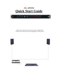
SOUNDCARD OPERATING MODES<br />
The Xone:<strong>3D</strong> soundcard can be configured to operate in one of two modes.<br />
Choose the mode that best suits the audio requirement of the computer<br />
application you are running. Before starting make sure you have installed the<br />
ASIO drivers for your selected USB port as described at the start of this guide.<br />
OPTICAL<br />
COAX<br />
SOUNDCARD<br />
MIX<br />
FX1<br />
CH2 PHONO<br />
TO CH1 and 4<br />
TO CH2<br />
TO CH3<br />
FROM CH3 PHONO<br />
FROM CH2 PHONO<br />
FROM MIX<br />
FROM FX1<br />
FROM MIDI CONTROLLERS<br />
TO CH1 and 4<br />
TO CH2<br />
TO CH3<br />
FROM CH3 PHONO<br />
FROM CH2 PHONO<br />
FROM MIX<br />
FROM FX1<br />
FROM MIDI CONTROLLERS<br />
MODE 1— 1 STEREO IN, 3 STEREO OUT<br />
This is the default mode.<br />
The soundcard sends one stereo signal to the<br />
computer. Select a soundcard input from:<br />
SPDIF coax input<br />
SPDIF optical input<br />
Main MIX<br />
FX1 send from the channels<br />
CH2 phono input preamp<br />
The soundcard returns three stereo signals<br />
from the computer. These route to rear panel<br />
soundcard output sockets and to the<br />
Xone:<strong>3D</strong> channel input selectors:<br />
1-2 to CH1 and CH4 inputs<br />
3-4 to CH2 input<br />
5-6 to CH3 input<br />
In this mode the SPDIF coax (RCA) and<br />
optical (Toslink) digital output may be<br />
selected from one of:<br />
Soundcard output 1-2<br />
Main MIX<br />
FX1 send from the channels<br />
CH3 phono input preamp<br />
MODE 2— 2 STEREO IN, 2 STEREO OUT<br />
The soundcard sends two stereo signals to the<br />
computer. Select soundcard input for:<br />
1-2 3-4 from:<br />
Main MIX SPDIF coax input<br />
FX1 send SPDIF optical input<br />
CH3 phono Main MIX<br />
FX1 send<br />
CH2 phono<br />
The soundcard returns two stereo signals<br />
from the computer. These route to rear panel<br />
soundcard output sockets and to the<br />
Xone:<strong>3D</strong> channel input selectors:<br />
1-2 to CH1 and CH4 inputs<br />
3-4 to CH2 input<br />
5-6 not used, no signal to CH3<br />
In this mode the SPDIF coax (RCA) and<br />
optical (Toslink) digital output may be<br />
selected from one of:<br />
Soundcard output 1-2<br />
Soundcard input 1-2<br />
Allen & Heath 10 <strong>XONE</strong>:<strong>3D</strong> User Guide
SOUNDCARD OPERATING MODES<br />
To configure the soundcard operating mode and to select its sources, run the<br />
Configuration Utility software provided on the Xone:<strong>3D</strong> Utility CD.<br />
Mode 1<br />
Mode 2<br />
Note:<br />
The current firmware version is<br />
displayed in the bottom left hand<br />
corner when the utility detects<br />
that the mixer is connected.<br />
For information about Firmware<br />
Update please refer to the<br />
section on Troubleshooting later<br />
in this user guide.<br />
TO CHANGE THE SOUNDCARD MODE<br />
Important Note: Close all audio and MIDI<br />
applications running on your PC before starting<br />
the Configuration Utility. Failure to do this may<br />
result in the PC losing connection with the mixer<br />
and both requiring a reboot.<br />
After closing the PC applications, start the<br />
Configuration Utility. The current operating<br />
mode is displayed. Use the pull-down menu to<br />
select the mode required.<br />
TO CHANGE THE IN/OUT SETTINGS<br />
The available settings depend on the mode<br />
currently selected. These are listed on the<br />
previous page. The soundcard sources and what<br />
signals are routed to the SPDIF connections are<br />
set using this utility. These may be changed while<br />
the PC is connected.<br />
Soundcard In = signal sent to the PC<br />
<strong>3D</strong> Digital Out = signal to the SPDIF outputs<br />
TO CHANGE THE MIDI SETTINGS<br />
Choose which MIDI channel is used to transmit<br />
the mixer MIDI messages between the Xone:<strong>3D</strong><br />
and the rest of the system.<br />
The MIDI messages associated with the mixer<br />
controls are configured in a MIDI ‘map’. Two<br />
maps are available— Map1 and Map2. Map2 is<br />
the default for most applications.<br />
More information on MIDI is provided later in<br />
this user guide.<br />
SPDIF DIGITAL INPUTS AND OUTPUTS<br />
SPDIF is a popular digital audio interfacing<br />
standard for connecting two channel (stereo)<br />
audio using a single coax (RCA phono socket) or<br />
optical fibre (Toslink socket) cable.<br />
The SPDIF inputs and outputs are available only<br />
when your computer is connected via the USB<br />
port. The computer provides the clocks needed<br />
for the soundcard to function.<br />
Sample rates of 44.1 and 48kHz are supported<br />
with the ability to interface with any digital source<br />
up to 192kHz.<br />
Allen & Heath 11 <strong>XONE</strong>:<strong>3D</strong> User Guide
+10!<br />
+6<br />
+3<br />
0<br />
-3<br />
-6<br />
-10<br />
OFF<br />
+6<br />
FILTER<br />
XFADE<br />
1X<br />
Y 2<br />
OFF<br />
CUE<br />
-15<br />
-20<br />
FX1<br />
FX2<br />
LEVEL<br />
HF<br />
MF<br />
LF<br />
0 +6<br />
0 +6<br />
LINE A<br />
LINE B<br />
-10 +10<br />
OFF<br />
OFF<br />
OO<br />
PRE<br />
+6<br />
+6<br />
MIXER SECTION — CHANNEL INPUT<br />
SC 1 - 2<br />
1<br />
1<br />
3<br />
2<br />
4<br />
1<br />
2<br />
3<br />
4<br />
FX 1-2 send controls<br />
These controls adjust the signal level that<br />
is sent from each channel to the two FX<br />
mix busses. These signals will appear at<br />
the RCA sockets on the rear of the unit.<br />
FX1 PRE switch determines whether the<br />
FX1 send signal is affected by the channel<br />
fader. When pressed the signal is prefader,<br />
when released post-fader.<br />
FX1 can also be sent to the input of the<br />
soundcard for processing or recording by<br />
the PC (see Soundcard Mode for details).<br />
FX2 is pre-fader (this can be changed<br />
internally - see User Options). FX2 can<br />
also be selected as the audio source for<br />
the Auto Beat detector (See BPM<br />
Detector).<br />
Input Selection<br />
Two switches select one of three possible<br />
stereo audio sources; Line A (RIAA phono<br />
on CH 2–4), Line B, or output from the<br />
computer via the internal soundcard (SC1-<br />
6). Switch 2 (SC) overrides switch 1<br />
(phono/line). The led indicator displays<br />
which source is active:<br />
CH1 CH2 CH3 CH4<br />
Switch1 gn LineA Phono Phono Phono<br />
Switch1 red LineB LineB LineB LineB<br />
Switch2 red SC1-2 SC3-4 SC5-6 SC1-2<br />
Channel Level Control<br />
This control has a range of +/- 10dB either<br />
side of the 0dB centre position. Use it to<br />
adjust the signal level of an audio source to<br />
give a nominal 0dB reading on the channel<br />
meter, with the peak level at or below<br />
+6dB. Turn LEVEL down if the +10 peak<br />
meter starts flashing.<br />
Channel Equalizer/Isolator<br />
The Xone:<strong>3D</strong> is equipped with a very<br />
powerful 3 band EQ stage providing a<br />
controlled +6dB of boost when fully<br />
clockwise, but full isolation (cut) of each<br />
band for dramatic effect when fully anticlockwise.<br />
Centre frequencies are set at:<br />
HF = 10kHz (high frequency, treble)<br />
MF = 1.2kHz (mid frequency)<br />
LF = 120Hz (low frequency, bass)<br />
Allen & Heath 12 <strong>XONE</strong>:<strong>3D</strong> User Guide
7<br />
+10!<br />
+6<br />
+3<br />
0<br />
-3<br />
-6<br />
-10<br />
OFF<br />
+6<br />
FILTER<br />
XFADE<br />
1X<br />
Y 2<br />
OFF<br />
CUE<br />
-15<br />
-20<br />
FX1<br />
FX2<br />
LEVEL<br />
HF<br />
MF<br />
LF<br />
0 +6<br />
0 +6<br />
LINE A<br />
LINE B<br />
-10 +10<br />
OFF<br />
OFF<br />
OO<br />
PRE<br />
+6<br />
+6<br />
MIXER SECTION — CHANNEL INPUT<br />
SC 1 - 2<br />
1<br />
5<br />
6<br />
8<br />
5<br />
6<br />
7<br />
8<br />
Filter/Crossfade Assignment<br />
The channel signal can be routed directly<br />
to the main mix or via either of the two<br />
filter/crossfade paths. Note that the<br />
crossfade affects the filter path only.<br />
Set the 3-position switch to its mid<br />
position to route the signal direct to the<br />
mix, or to its left or right positions to<br />
route the signal to filter-1/crossfade-X or<br />
filter-2/crossfade-Y respectively.<br />
To enable the crossfader check that the<br />
XFADE ON switch above the filter1<br />
controls is pressed.<br />
Cue Switch<br />
Press the cue switch to listen to the channel<br />
pre-fade signal in the headphones and see its<br />
level on the main meters. The led indicator<br />
ring around the switch lights when selected.<br />
The big red CUE ACTIVE indicator also<br />
lights to warn that you are monitoring the<br />
channel signal rather than the main mix.<br />
Press the switch to deselect cue. The<br />
switches are interlocked; pressing another<br />
one turns off the previous selection.<br />
Channel Meter<br />
Displays the channel signal level. It is pre-EQ<br />
and pre-fader. This means it is not affected<br />
by the EQ or fader position.<br />
The channel level control should be set so<br />
that the meter averages around ‘0’ with<br />
loudest peaks no higher than ‘+6’. Turn<br />
down the level control if the +10 peak<br />
indicator lights.<br />
Channel Fader<br />
A high quality, smooth travel dual-rail fader<br />
adjusts the channel signal level from fully off<br />
to fully on.<br />
Allen & Heath 13 <strong>XONE</strong>:<strong>3D</strong> User Guide
4<br />
PHONES<br />
L<br />
2<br />
2<br />
CUE<br />
4<br />
3<br />
2<br />
3<br />
1<br />
3<br />
1<br />
1<br />
+10!<br />
+6<br />
+3<br />
0<br />
-3<br />
-20<br />
4<br />
0<br />
4<br />
-6<br />
-10<br />
-15<br />
0<br />
R<br />
MIX<br />
9<br />
10<br />
9<br />
10<br />
MONITOR<br />
CUE ACTIVE<br />
0<br />
MIXER SECTION — MIX AND MONITOR<br />
5<br />
5<br />
5<br />
6<br />
6<br />
FX 1<br />
FX 2<br />
ADD MIX<br />
6<br />
7<br />
8<br />
11<br />
7<br />
7<br />
8<br />
8<br />
9<br />
10<br />
1<br />
2<br />
3<br />
5<br />
6<br />
LEVEL<br />
7<br />
1<br />
2<br />
3<br />
4<br />
5<br />
6<br />
7<br />
Mix / Monitor Meters<br />
The main meters follow the selected<br />
monitor source. The meter reads ‘0’ for<br />
an XLR output of +4dBu. The mixer<br />
should be operated with these meters<br />
averaging around ‘0’ with loudest peaks no<br />
higher than ‘+6’.<br />
Mix Master Level Control<br />
A rotary master control adjusts the level of<br />
the main mix XLR outputs feeding the house<br />
sound system. This does not affect the<br />
monitor output or the meter reading.<br />
Monitor Master Level Control<br />
Adjusts the level of the signal to the stereo<br />
monitor RCA output. This does not affect<br />
the headphones. The monitor output could<br />
be used for a booth monitor, recording or<br />
an additional zone feed.<br />
Cue Active LED<br />
A large red led indicator lights when a<br />
channel CUE is active. This indicates that<br />
the selected channel CUE signal is heard in<br />
the headphones and displayed on the<br />
monitor meters.<br />
Monitor Select Switches<br />
In the normal up position the headphones<br />
and meters monitor the pre-level main mix.<br />
Press these switches to select either of the<br />
stereo FX mixes as the headphones and<br />
meter source. Note that this does not affect<br />
the main mix or monitor outputs.<br />
Cue / Add Mix Control<br />
Allows the main mix output to be added to<br />
the CUE signal. Turned fully anticlockwise,<br />
only the active CUE signal is heard through<br />
the headphones when selected. Gradually<br />
turning clockwise introduces the main mix<br />
output to the headphones, adding to the active<br />
CUE. This does not affect the meters.<br />
Headphones Level Control<br />
Adjusts the level of the headphones signal.<br />
!<br />
Warning ! To avoid damage to your hearing do not operate the<br />
headphones or sound system at excessively high volume. Continued<br />
exposure to high volume sound can cause frequency selective or wide<br />
range hearing loss.<br />
Allen & Heath 14 <strong>XONE</strong>:<strong>3D</strong> User Guide
DEPTH<br />
1 2<br />
1+2 ASSIGN<br />
XFADE<br />
RES<br />
4<br />
3<br />
2<br />
1<br />
0<br />
20Hz<br />
5<br />
FILTER 1 ON<br />
LFO<br />
TAP<br />
TEMPO<br />
6<br />
7<br />
8<br />
9<br />
10<br />
MILD WILD<br />
MIXER SECTION — FILTERS and LFO<br />
HPF<br />
BPF<br />
LPF<br />
ON<br />
FREQ<br />
20kHz<br />
1<br />
2<br />
3<br />
4<br />
5<br />
6<br />
7<br />
8<br />
9<br />
1<br />
2<br />
3<br />
4<br />
5<br />
6<br />
7<br />
8<br />
9<br />
LFO Tap Tempo button<br />
Tap the tap tempo button in time with the beat<br />
to set the frequency of the LFO.<br />
LFO Depth control<br />
When assigned, the LFO modulates the filter with a<br />
cyclic frequency sweep effect in time to the beat set<br />
using the tap tempo button. The depth control<br />
adjusts how much effect the LFO has on the filter<br />
effect from fully off to very deep.<br />
LFO Filter Assign Switch<br />
Use this switch to assign the LFO to either or both<br />
the filters.<br />
Resonance Control<br />
This produces the classic analogue VCF sound by<br />
feeding some of the filter output back to its input.<br />
The control ranges from ‘mild’ producing a very<br />
subtle effect, to ‘wild’ producing a dramatic phase<br />
effect with feedback just short of oscillation.<br />
HPF Button<br />
Turns on the high pass (bass cut) filter slope. The<br />
light ring around the button illuminates when<br />
selected.<br />
BPF Button<br />
Turns on the band pass (bell shaped) filter slope.<br />
The light ring around the button illuminates when<br />
selected.<br />
LPF Button<br />
Turns on the low pass (treble cut) filter slope. The<br />
light ring around the button illuminates when<br />
selected.<br />
Frequency Sweep Control<br />
This control sets the –3dB cut-off frequency of the<br />
filter. It ranges from very low frequency (20Hz) to<br />
very high (20kHz).<br />
Filter On Switch<br />
Switches the filter on and off. The light ring around<br />
the button illuminates when the filter is active.<br />
Allen & Heath 15 <strong>XONE</strong>:<strong>3D</strong> User Guide
4<br />
DEPTH<br />
1 2<br />
1+2 ASSIGN<br />
XFADE<br />
RES<br />
3<br />
2<br />
1<br />
20Hz<br />
MIXER SECTION — FX RTN & CROSSFADER<br />
4<br />
0<br />
4<br />
5<br />
6<br />
3<br />
7<br />
2<br />
8<br />
1<br />
9<br />
0 10<br />
4<br />
3<br />
2<br />
1<br />
0<br />
5<br />
5<br />
FILTER 1 ON<br />
6<br />
7<br />
8<br />
9<br />
10<br />
LFO<br />
FX1<br />
RTN<br />
FX2<br />
RTN<br />
TAP<br />
TEMPO<br />
6<br />
7<br />
8<br />
9<br />
10<br />
MILD WILD<br />
HPF<br />
BPF<br />
LPF<br />
ON<br />
FREQ<br />
20kHz<br />
3<br />
1<br />
XFADE CURVE<br />
FROM INPUT CHANNEL<br />
1<br />
2<br />
3<br />
4<br />
FILTER / XFADE SELECT<br />
X1 2Y<br />
OFF<br />
Allen & Heath 16 <strong>XONE</strong>:<strong>3D</strong> User Guide<br />
DC<br />
FILTER 1 MIX BUS<br />
FILTER 2 MIX BUS<br />
MAIN LR MIX BUS<br />
FILTER 2 MIX<br />
FILTER 1 MIX<br />
VCA<br />
VCA<br />
XFADE ON<br />
XFADE CURVE<br />
X Y<br />
X<br />
CROSSFADER<br />
LFO DEPTH<br />
FILTER 1 FILTER 2<br />
TAP TEMPO<br />
FX Return Controls<br />
These controls route the incoming signal<br />
from the stereo FX1 and FX2 Return RCA<br />
connectors on the rear panel to the mix.<br />
They adjust how much return signal is<br />
added to the mix.<br />
Crossfader<br />
This lets you fade between signals routed to<br />
either side, typically to fade smoothly into a<br />
new music track or to creatively layer<br />
sounds when scratch or cut mixing.<br />
The crossfader is a VCA controller which<br />
affects the level of signals routed via the<br />
filters. Make sure the toggle switches on the<br />
channels you wish to fade are set to X or Y<br />
as appropriate.<br />
The crossfader may be removed for service<br />
or replacement. Instructions are provided<br />
later in this user guide.<br />
Xfade on switch<br />
Press this switch to activate the crossfader.<br />
XFade Curve Control<br />
This control adjusts the crossfader curve<br />
between dipped response, ideal for seamless<br />
beat mixing, and fast-attack, suitable for<br />
scratch or cut mixing .<br />
2<br />
Y
FRONT CONTROLS & CONNECTORS<br />
PHONES<br />
1<br />
2<br />
3<br />
4<br />
LF<br />
-12 +12 -12 +12 0<br />
Allen & Heath 17 <strong>XONE</strong>:<strong>3D</strong> User Guide<br />
HF<br />
MIC<br />
LEVEL<br />
1 2 3 4<br />
Headphones Outputs<br />
Stereo 1/4” TRS jack and 3.5mm mini-jack. Plug in<br />
good quality stereo headphones intended for DJ<br />
monitoring. Use closed-ear headphones that<br />
provide maximum acoustic isolation when cueing<br />
your sources. We recommend that you use high<br />
quality headphones rated between 30 to 100 ohms<br />
impedance. 8 ohm headphones are not<br />
recommended.<br />
Mic EQ Controls<br />
The MIC equaliser provides a tool to adjust the<br />
tonal quality of the sound to correct source<br />
problems such as microphone response, proximity<br />
effect, noise and feedback, to help the voice cut<br />
through the mix, or to adjust the overall ‘feel’.<br />
Start with the EQ controls set to their mid (flat)<br />
position, then adjust to achieve the desired sound.<br />
Mic Input<br />
Balanced XLR. Plug in a DJ, guest or announcement<br />
microphone here. Use a good quality low<br />
impedance dynamic mic such as those specifically<br />
designed for vocals. Do not use high impedance or<br />
unbalanced microphones, or condenser types which<br />
require phantom power. Use the best professional<br />
grade balanced cables and connectors you can<br />
afford as these are typically subject to intense use<br />
and abuse in the club environment.<br />
Mic Level Control<br />
Adjusts the input sensitivity of the Mic channel to<br />
match the connected source to the console 0dB<br />
operating level.<br />
When the Mic channel is not in use, always turn the<br />
level control fully anti-clockwise to prevent<br />
unwanted noise from this sensitive input entering<br />
the main Mix.<br />
10
CAUTION<br />
WARNING: FOR CONTINUED PROTECTION AGAINST RISK OF FIRE<br />
REPLACE FUSE WITH SAME TYPE AND RATING.<br />
ATTENTION: REMPLACER LE FUSIBLE AVEC<br />
UN DES MEMES CARACTERISTIQUES.<br />
WARNING: THIS APPARATUS MUST BE EARTHED.<br />
TO REDUCE THE RISK OF FIRE OR ELECTRIC SHOCK<br />
DO NOT EXPOSE APPARATUS TO RAIN OR MOISTURE.<br />
SERIAL No:<br />
1<br />
4<br />
0<br />
I<br />
OFF<br />
ON<br />
AC MAINS IN ~<br />
T500mAL 250V 20mm<br />
FUSE<br />
100 - 240V~<br />
47-63Hz ~ 30W MAX MADE IN THE UK BY ALLEN & HEATH LIMITED<br />
1<br />
MIX OUT<br />
LEFT RIGHT<br />
INPUT 4<br />
PHONO L R<br />
AC Mains Input<br />
IEC cable with moulded mains plug<br />
suitable for your local supply<br />
Important: Read the SAFETY<br />
INSTRUCTIONS sheet<br />
included with the Xone:<strong>3D</strong> and<br />
printed on the rear panel.<br />
Check that the correct mains lead<br />
with moulded plug has been<br />
supplied with your console. The<br />
power supply accepts mains<br />
voltages within the range 100-240V<br />
without changing any fuses or<br />
settings.<br />
Ensure that the IEC mains plug is<br />
pressed fully into the rear panel<br />
socket before switching on.<br />
Note: It is standard practice to<br />
turn connected power amplifiers<br />
down or off before switching the<br />
console on or off. This prevents<br />
any audible switch-on thumps.<br />
FX1-2 Line Return Input<br />
RCA phono.<br />
Connect stereo line level sources<br />
such as the return signal from<br />
external effects units. These inputs<br />
are routed directly to the main mix<br />
as the default setting, but this can<br />
be changed internally to send them<br />
to the Filters and crossfader (see<br />
User Options)<br />
REAR CONNECTORS<br />
INPUT 3<br />
PHONO L R<br />
INPUT 2<br />
PHONO L R<br />
Allen & Heath 18 <strong>XONE</strong>:<strong>3D</strong> User Guide<br />
FX2 SEND<br />
INPUT 1<br />
LINE<br />
A<br />
L R<br />
FX RETURNS<br />
FX1 L R<br />
LINE L R LINE L R LINE L R LINE<br />
B<br />
L R FX2 L R<br />
L<br />
R<br />
3<br />
MONITOR<br />
L<br />
R<br />
FX1 SEND<br />
L<br />
R<br />
2<br />
3<br />
5<br />
2 4 5<br />
CH1<br />
L<br />
CH2<br />
R<br />
SOUNDCARD OUTPUTS<br />
CH3<br />
L<br />
CH4<br />
R<br />
CH5<br />
L<br />
CH6<br />
R<br />
IN<br />
OUT<br />
SPDIF<br />
DIGITAL AUDIO<br />
OPTICAL<br />
IN OUT<br />
GAME/MIDI<br />
CH1-4 Stereo Line Input<br />
RCA phono.<br />
Connect stereo line level music<br />
sources such as CD, MD, DAT,<br />
drum machines, keyboards or<br />
other instruments. Do not<br />
connect turntables which require<br />
RIAA equalisation. Alternatively,<br />
you can connect to jack sources<br />
using a cable with RCA to jack<br />
adapters. Avoid using low grade<br />
cables such as those often supplied<br />
with domestic equipment as these<br />
can quickly prove unreliable in use.<br />
CH2-4 Stereo Phono Input<br />
RCA phono.<br />
Plug in turntables with magnetic<br />
cartridges requiring RIAA<br />
equalisation. For non-RIAA<br />
turntables plug into the LINE input<br />
instead. Do not plug in line level<br />
sources to the phono inputs as<br />
these will overload the preamp and<br />
cause severe high level distortion.<br />
Chassis Earth Terminal<br />
A screw terminal is provided for<br />
connecting the earth straps from<br />
turntables. This connection earths<br />
the metal parts of the turntable to<br />
reduce hum, buzz or similar<br />
audible noise getting into the<br />
system.<br />
IN<br />
MIDI<br />
OUT<br />
USB<br />
TO PC<br />
FOOT<br />
SWITCH
CAUTION<br />
WARNING: FOR CONTINUED PROTECTION AGAINST RISK OF FIRE<br />
REPLACE FUSE WITH SAME TYPE AND RATING.<br />
ATTENTION: REMPLACER LE FUSIBLE AVEC<br />
UN DES MEMES CARACTERISTIQUES.<br />
WARNING: THIS APPARATUS MUST BE EARTHED.<br />
TO REDUCE THE RISK OF FIRE OR ELECTRIC SHOCK<br />
DO NOT EXPOSE APPARATUS TO RAIN OR MOISTURE.<br />
SERIAL No:<br />
6<br />
7<br />
8<br />
9<br />
0<br />
I<br />
OFF<br />
ON<br />
AC MAINS IN ~<br />
T500mAL 250V 20mm<br />
FUSE<br />
100 - 240V~<br />
47-63Hz ~ 30W MAX MADE IN THE UK BY ALLEN & HEATH LIMITED<br />
MIX OUT<br />
LEFT RIGHT<br />
INPUT 4<br />
PHONO L R<br />
Mix Output<br />
Balanced XLR. This is the main<br />
output that feeds the house PA<br />
system. Plug into the house<br />
processor/amplifier system using<br />
balanced cables. Use balanced<br />
cables and equipment.<br />
Monitor Output<br />
RCA phono. Provides a line level<br />
stereo feed to the DJ local monitor<br />
amplifier system. It is not affected<br />
by the master fader or cue system.<br />
Can also be used as an alternative<br />
zone or record output.<br />
INPUT 3<br />
PHONO L R<br />
INPUT 2<br />
PHONO L R<br />
Allen & Heath 19 <strong>XONE</strong>:<strong>3D</strong> User Guide<br />
FX2 SEND<br />
INPUT 1<br />
LINE<br />
A<br />
L R<br />
FX RETURNS<br />
FX1 L R<br />
LINE L R LINE L R LINE L R LINE<br />
B<br />
L R FX2 L R<br />
L<br />
R<br />
MONITOR<br />
FX1-2 Send Output<br />
RCA phono. Depending on the<br />
application of the FX mix, these stereo<br />
line level outputs can be used to feed<br />
samplers and other effects units, an<br />
additional monitor, zone or recorder.<br />
Soundcard Outputs<br />
RCA phono.<br />
Outputs from the internal soundcard.<br />
These are always available irrespective of<br />
the source selection on the stereo<br />
channels. These outputs could be fed to<br />
an additional mixer or processor before<br />
being brought back into the mix.<br />
Depending on the soundcard operating<br />
mode, signals are available on sockets 1-6<br />
or 1-4.<br />
REAR CONNECTORS<br />
L<br />
R<br />
FX1 SEND<br />
L<br />
R<br />
CH1<br />
L<br />
CH2<br />
R<br />
SOUNDCARD OUTPUTS<br />
CH3<br />
L<br />
CH4<br />
R<br />
CH5<br />
L<br />
CH6<br />
R<br />
IN<br />
OUT<br />
SPDIF<br />
DIGITAL AUDIO<br />
6 7 8 9 10<br />
10<br />
OPTICAL<br />
IN OUT<br />
GAME/MIDI<br />
IN<br />
MIDI<br />
OUT<br />
USB<br />
TO PC<br />
FOOT<br />
SWITCH<br />
SPDIF DIGITAL INPUTS<br />
AND OUTPUTS<br />
SPDIF is a popular digital audio interfacing<br />
standard for connecting two channel<br />
(stereo) audio using a single coax (RCA<br />
phono socket) or optical fibre (Toslink<br />
socket) cable.<br />
For reliable connection use a 75 ohm coax<br />
cable intended for this function. Avoid<br />
the use of cheap audio cables. Use<br />
purpose made optical fibre cables for<br />
connection using the Toslink port. Make<br />
sure the blanking plugs provided are fitted<br />
to any unused Toslink sockets.<br />
The SPDIF inputs and outputs are available<br />
only when your computer is connected via<br />
the USB port. The computer provides the<br />
clocks needed for the soundcard to<br />
function.<br />
Sample rates of 44.1 and 48kHz are<br />
supported with the ability to interface<br />
with any digital source up to 192kHz.<br />
Use the Xone:<strong>3D</strong> Configuration Utility<br />
software to select which signals are<br />
routed to the SPDIF connectors.
WARNING: FOR CONTINUED PROTECTION AGAINST RISK OF FIRE<br />
REPLACE FUSE WITH SAME TYPE AND RATING.<br />
ATTENTION: REMPLACER LE FUSIBLE AVEC<br />
UN DES MEMES CARACTERISTIQUES.<br />
WARNING: THIS APPARATUS MUST BE EARTHED.<br />
TO REDUCE THE RISK OF FIRE OR ELECTRIC SHOCK<br />
DO NOT EXPOSE APPARATUS TO RAIN OR MOISTURE.<br />
SERIAL No:<br />
0<br />
I<br />
11<br />
12<br />
CAUTION<br />
OFF<br />
ON<br />
AC MAINS IN ~<br />
T500mAL 250V 20mm<br />
FUSE<br />
100 - 240V~<br />
47-63Hz ~ 30W MAX MADE IN THE UK BY ALLEN & HEATH LIMITED<br />
MIDI Input / Output<br />
5 pin DIN socket.<br />
Connect to either a MIDI<br />
interface or directly to MIDI<br />
compatible equipment using a<br />
standard 5 pin DIN (MIDI) lead.<br />
The MIDI output socket data<br />
duplicates what is sent via the USB<br />
connection to the PC, and to the<br />
gameport.<br />
MIDI in can be used to remotely<br />
control the status of all switches<br />
that have associated LED light rings<br />
(with the exception of the BPM,<br />
LFO and Stop/Start.<br />
You can connect the MIDI OUT of<br />
one Xone:<strong>3D</strong> to the MIDI IN of<br />
another.<br />
USB Connector<br />
USB (Universal Serial Bus) V1.1 is<br />
an external peripheral interface<br />
standard for data transmission.<br />
Xone:<strong>3D</strong> USB works at 12Mbps<br />
and provides up to 8<br />
uncompressed audio channels. It is<br />
fully compatible with USB2.<br />
The USB connection is used to<br />
send/receive audio and MIDI data<br />
between the Xone:<strong>3D</strong> and the<br />
connected computer. It is also the<br />
means by which the firmware<br />
(operating software) in the<br />
Xone:<strong>3D</strong> can be updated if<br />
necessary.<br />
Use a standard USB type A to B<br />
lead to connect to your computer.<br />
This is supplied with the Xone:<strong>3D</strong>.<br />
REAR CONNECTORS<br />
MIX OUT<br />
LEFT RIGHT<br />
INPUT 4<br />
PHONO L R<br />
INPUT 3<br />
PHONO L R<br />
INPUT 2<br />
PHONO L R<br />
13 14<br />
11 12<br />
Gameport Connector<br />
The gameport connector (15pin D-type)<br />
lets you add additional controllers such as<br />
an analogue joystick, or a third MIDI<br />
output socket using a standard gameport<br />
to MIDI adapter.<br />
Note; this port has no MIDI input<br />
connection.<br />
This interface will convert the movement<br />
of a connected joystick into MIDI CC and<br />
Note information; it cannot be used to<br />
control PC games, so don’t try it with<br />
your latest flight sim…..<br />
It is also be possible to build a custom<br />
interface using general purpose switches<br />
and potentiometers. We recommend 10k<br />
or 20k ohm linear law pots. A simple<br />
schematic is shown here.<br />
Allen & Heath 20 <strong>XONE</strong>:<strong>3D</strong> User Guide<br />
FX2 SEND<br />
13<br />
14<br />
INPUT 1<br />
LINE<br />
A<br />
L R<br />
FX RETURNS<br />
FX1 L R<br />
LINE L R LINE L R LINE L R LINE<br />
B<br />
L R FX2 L R<br />
L<br />
R<br />
MONITOR<br />
L<br />
R<br />
FX1 SEND<br />
L<br />
R<br />
CH1<br />
L<br />
CH2<br />
R<br />
SOUNDCARD OUTPUTS<br />
CH3<br />
L<br />
CH4<br />
R<br />
CH5<br />
L<br />
CH6<br />
R<br />
+5V<br />
IN<br />
OUT<br />
+5V<br />
SPDIF<br />
DIGITAL AUDIO<br />
+5V<br />
+5V<br />
OPTICAL<br />
IN OUT<br />
MIDI OUT 2<br />
GAME/MIDI<br />
9 10 11 12 13 14 15<br />
NC<br />
1 2 3 4 5 6 7 8<br />
Footswitch Connector<br />
This 1/4” TRS socket is used to connect a<br />
footswitch or expression pedal as an<br />
additional MIDI controller. Most standard<br />
foot pedals should be satisfactory., for<br />
example the Roland EV-5.<br />
+5V<br />
IN<br />
MIDI<br />
+5V<br />
OUT<br />
USB<br />
TO PC<br />
FOOT<br />
SWITCH
MIDI<br />
PULL<br />
MIX<br />
MODE<br />
3<br />
2<br />
1<br />
BPM<br />
OFF<br />
4<br />
0<br />
CLOCK<br />
+<br />
PUSH<br />
LFO<br />
DEPTH<br />
1 2<br />
1+2 ASSIGN<br />
MIXER SECTION — BPM COUNTER<br />
START<br />
STOP<br />
TAP<br />
AUTO BPM<br />
SELECT<br />
FX2<br />
4<br />
5<br />
6<br />
3<br />
7<br />
2<br />
8<br />
1<br />
9<br />
0 10<br />
4<br />
3<br />
2<br />
1<br />
0<br />
5<br />
5<br />
MIDI CH<br />
6<br />
7<br />
8<br />
9<br />
10<br />
FX1<br />
RTN<br />
FX2<br />
RTN<br />
TAP<br />
TEMPO<br />
6<br />
7<br />
8<br />
9<br />
10<br />
RESET<br />
1<br />
2<br />
3<br />
1<br />
2<br />
3<br />
BPM Display<br />
Displays the tempo of an analysed piece of<br />
music, rounded up to the nearest whole<br />
number.<br />
On power-up, and when the detector is<br />
reset, the display will show a line of three<br />
dashes.<br />
When an audio source is routed to the<br />
auto beat detector a dot in the bottom<br />
right hand corner will flash to indicate that<br />
BPM analyses is taking place.<br />
The display can also show the BPM to the<br />
nearest decimal place by pressing and<br />
holding the TAP button. This will shift all<br />
digits one place to the left.<br />
MIDI Start / Stop Button<br />
Sends MIDI start/stop messages to any<br />
connected sequencer. Note that these<br />
messages are sent on release of the switch.<br />
Pressing and holding this switch will reset<br />
the auto BPM detector, but won’t change<br />
the current status of the Stop/Start control.<br />
The LED ring associated with this control<br />
will glow RED when a Start message is sent.<br />
MIDI Clock Push / Pull Switch<br />
When attempting to get a sequencer, such as<br />
Ableton Live 5, to play in time with another<br />
music source, for example a CD or turntable<br />
which has been analysed by the auto beat<br />
detector, it is not always possible to get it to<br />
start exactly at the beginning of a bar. This<br />
control lets the DJ speed up or slow down<br />
the MIDI clock, rather like pushing or pulling<br />
a turntable platter when beat matching.<br />
Pulling the lever to the left will slow the<br />
clock and the BPM reading will drop, pushing<br />
the lever to the right will speed up the clock<br />
and the BPM reading will rise.<br />
When released, the MIDI clock will revert to<br />
the originally displayed BPM.<br />
You can manually set the BPM to any speed<br />
between 70 and 400 by pulling or pushing<br />
the lever; when the desired speed is<br />
indicated on the display, press the TAP<br />
button to lock the MIDI clock to this speed.<br />
To fine tune the BPM to an exact figure,<br />
press and hold the TAP button and when the<br />
decimal is displayed, the speed can be altered<br />
by 0.1BPM again by using the Push/Pull lever.<br />
Allen & Heath 21 <strong>XONE</strong>:<strong>3D</strong> User Guide
MIDI<br />
PULL<br />
MIX<br />
MODE<br />
3<br />
2<br />
1<br />
BPM<br />
OFF<br />
4<br />
0<br />
CLOCK<br />
+<br />
PUSH<br />
LFO<br />
DEPTH<br />
1 2<br />
1+2 ASSIGN<br />
MIXER SECTION — BPM COUNTER<br />
START<br />
STOP<br />
TAP<br />
AUTO BPM<br />
SELECT<br />
FX2<br />
4<br />
5<br />
6<br />
3<br />
7<br />
2<br />
8<br />
1<br />
9<br />
0 10<br />
4<br />
3<br />
2<br />
1<br />
0<br />
5<br />
5<br />
MIDI CH<br />
6<br />
7<br />
8<br />
9<br />
10<br />
FX1<br />
RTN<br />
FX2<br />
RTN<br />
TAP<br />
TEMPO<br />
6<br />
7<br />
8<br />
9<br />
10<br />
RESET<br />
6<br />
7<br />
4<br />
5<br />
8<br />
4<br />
5<br />
BPM Tap Tempo Button<br />
This control is used to tap in a beat manually<br />
at any speed between 70 and 400 BPM. The<br />
taps are averaged, so the greater number of<br />
taps the more accurate the result.<br />
The tap button can also be used as a guide<br />
for the auto beat detector on complex<br />
rhythms by helping the analyser lock onto<br />
the correct pattern, for instance drum ‘n<br />
bass tracks can occasionally be displayed at<br />
half the actual BPM. By tapping in the<br />
approximate beat the analyser will re-sync to<br />
the correct tempo.<br />
Pressing and holding the tap tempo button<br />
shifts the BPM display one place to the left<br />
so that the decimal can be shown.<br />
When the BPM is being speeded up or down<br />
using the push/pull lever, pressing the tap<br />
button will store the currently displayed<br />
tempo.<br />
The light ring associated with this control<br />
will flash in time with the current BPM<br />
speed, usually along with the kick drum,<br />
though occasionally the detector will<br />
synchronize to other rhythmic elements of a<br />
track such as a hi-hat line. This will not<br />
affect its accuracy. Tapping a few beats in<br />
manually will force the detector to re-sync<br />
to the beat.<br />
Auto BPM Audio Source Switch<br />
This selects the audio source for the auto<br />
beat detection circuit.<br />
If MIX is selected all music played through<br />
the main outputs of the Xone:<strong>3D</strong> will be<br />
analysed. This can be used to ensure that a<br />
mix compilation or DJ set is held at a strict<br />
tempo.<br />
Select FX2 if you are using auto BPM<br />
detection to synchronize a remote<br />
sequencer to an audio source played through<br />
the Xone:<strong>3D</strong>, and are returning the audio<br />
output from the sequencer back into the<br />
mix. Ensure that all FX2 level pots are<br />
turned fully off except on the channel playing<br />
the track that you wish to synchronize to. If<br />
more than one channel at a time is routed to<br />
the FX2 mix buss it may confuse the BPM<br />
detector and result in an incorrect reading.<br />
Switch to the OFF position if you want to<br />
enter the BPM manually and do not want any<br />
audio source to influence the tempo.<br />
Allen & Heath 22 <strong>XONE</strong>:<strong>3D</strong> User Guide
MIDI<br />
PULL<br />
MIX<br />
MODE<br />
3<br />
2<br />
1<br />
BPM<br />
OFF<br />
4<br />
0<br />
START<br />
STOP<br />
CLOCK<br />
+<br />
PUSH<br />
TAP<br />
AUTO BPM<br />
SELECT<br />
FX2<br />
4<br />
5<br />
6<br />
3<br />
7<br />
2<br />
8<br />
1<br />
9<br />
0 10<br />
4<br />
3<br />
2<br />
1<br />
0<br />
5<br />
5<br />
MIDI CH<br />
LFO<br />
FX1<br />
RTN<br />
FX2<br />
RTN<br />
TAP<br />
TEMPO<br />
6<br />
7<br />
8<br />
9<br />
10<br />
DEPTH<br />
1 2<br />
1+2 ASSIGN<br />
6<br />
7<br />
8<br />
9<br />
10<br />
RESET<br />
MIXER SECTION — LFO<br />
6<br />
7<br />
8<br />
6<br />
7<br />
8<br />
LFO Tap Tempo button<br />
Tapping this button will set the speed of the<br />
LFO (low frequency oscillator) within the<br />
range of 0.25Hz - 3.33Hz (15 - 200 BPM)<br />
The LFO speed can be displayed on the BPM<br />
meter by pressing and holding this button for<br />
more than 2 seconds. This will also let you<br />
set the LFO speed manually using the push/<br />
pull lever to raise or lower the speed from<br />
its current setting.<br />
One very useful feature is the ability to copy<br />
the current BPM speed to the LFO. To do<br />
this, press and hold the LFO tap tempo<br />
button for longer than 2 seconds until the<br />
LFO speed is displayed on the BPM screen,<br />
then press the BPM tap button. The LFO<br />
speed will now be exactly the same as the<br />
BPM.<br />
Note: The phase of the LFO will be set the<br />
moment the BPM tap button is pressed<br />
(whilst holding down the LFO tap button).<br />
This will let you synchronize the LFO to a<br />
particular sound on any track being fed to<br />
the auto beat detector. For example,<br />
pressing the BPM tap button on the beat will<br />
sync the LFO to the kick drum.<br />
The light ring associated with this control<br />
will flash in time with the current LFO speed.<br />
LFO Depth control<br />
This control sets the level at which the filters<br />
will be modulated by the LFO. This works<br />
together with the filter frequency control.<br />
The maximum LFO filter modulation will<br />
occur if the LFO Depth control is fully<br />
clockwise with the filter frequency control<br />
fully anti-clockwise.<br />
LFO Assign switch<br />
Selects which filter will be modulated by the<br />
LFO. In its left position Filter 1 only is<br />
modulated, in the right hand position Filter 2<br />
only is modulated. In the centre position<br />
both Filter 1 and Filter 2 will be modulated<br />
by equal amounts.<br />
Allen & Heath 23 <strong>XONE</strong>:<strong>3D</strong> User Guide
A B C<br />
E F<br />
JOG / SELECT<br />
I J<br />
G<br />
K<br />
MIDI CONTROL SECTION<br />
D<br />
H<br />
L<br />
1<br />
2<br />
3<br />
4<br />
5<br />
6<br />
7<br />
Overlay Sheet<br />
An overlay sheet associated with<br />
a particular application may be<br />
fitted over the MIDI section<br />
controls to identify their<br />
function. Pull off the fader<br />
knobs before fitting the sheet.<br />
Refit the knobs once the sheet is<br />
in place.<br />
1<br />
2<br />
3<br />
4<br />
5<br />
6<br />
7<br />
Rotary Encoders<br />
Turning an encoder produces MIDI CC<br />
(continuous controller) messages with a<br />
unique controller number in two’s<br />
compliment binary encoding. Refer to the<br />
MIDI mapping diagram for the differences<br />
between Map 1 and 2 for these controls.<br />
These encoders feature a built in<br />
momentary push switch. Pressing down on<br />
the encoder knob activates the switch and<br />
sends a “note on” MIDI message, releasing<br />
the switch sends a corresponding “note off”<br />
message.<br />
Rotary Potentiometers<br />
These controls are standard<br />
potentiometers with end stops and a centre<br />
detent for easy setting. Turning a pot from<br />
left to right will send MIDI messages with a<br />
unique CC number and a control value<br />
from 0 to 127.<br />
Linear Faders<br />
Moving a linear fader will send a MIDI<br />
message with a unique CC number and a<br />
control value from 0 (bottom) to 127 (top).<br />
Push Buttons<br />
There are 24 momentary action switches<br />
coded with letters A through to X for easy<br />
identification. Pressing a switch will send a<br />
unique “note on” MIDI message. Releasing<br />
the switch sends a corresponding “note off”<br />
message.<br />
Rotary Encoder<br />
A rotary encoder with switch, as above.<br />
Jog Wheel<br />
The jog wheel features an optical encoder,<br />
which produces CC messages in a similar<br />
way to the other encoders. Switches are<br />
located at the top, bottom, left and right of<br />
the wheel. Pushing down on the face of the<br />
wheel sends note on / note off messages.<br />
Illuminated Push Buttons<br />
Momentary action switches with red light<br />
ring indicators. Pressing a switch will send<br />
a “note on” MIDI message and turn on the<br />
indicator. Pressing the switch again will<br />
send another “note on” message and switch<br />
off the indicator.<br />
Allen & Heath 24 <strong>XONE</strong>:<strong>3D</strong> User Guide
MAP 1<br />
MAP 2<br />
MIDI CONTROL SECTION<br />
MIDI Messages<br />
The diagram below shows which controls are associated with MIDI CC (continuous<br />
controller) and note on/off messages. These controls send the MIDI messages shown<br />
when operated. The switch light ring indicators (except for start/stop and tap tempo)<br />
may be turned on or off by incoming MIDI messages.<br />
FOOTSWITCH CC4 - DOWN=127, UP=0<br />
JOYSTICK X=CC3 - LEFT=127, RIGHT=0<br />
E0 D-1 E-1 D0<br />
CC32 CC33 CC34 CC35<br />
CC9<br />
CC8<br />
CC19<br />
CC11<br />
CC10<br />
CC13<br />
CC12<br />
CC15<br />
CC14<br />
CC18 CC17 CC16<br />
F0 D#-1 F-1 D#0<br />
A B C D<br />
C1 A-1 F#-1 G#0<br />
E F G H<br />
C#1<br />
I<br />
A#-1<br />
J<br />
C#-1<br />
G-1<br />
K<br />
A0<br />
L<br />
HPF<br />
C5<br />
HPF<br />
D#5<br />
CC36<br />
CC37 A#-2<br />
CC45<br />
B-2<br />
JOG SELECT<br />
C0<br />
A-2<br />
D1 B-1 G#-1 A#0<br />
Y=CC1 - UP=127, DOWN=0 FINGER BUTTON = C#-2 THUMB BUTTON = D-2<br />
CC6<br />
B4<br />
A#4<br />
ALLEN&HEATH F5 F#5 G5 G#5 A5 A#5 B6 C6<br />
C#6 D6 D#6 E6 F6 F#6 G6 G#6<br />
127<br />
0<br />
BPF<br />
LPF<br />
MIDI Map<br />
Two control mappings are available. Run the Xone:<strong>3D</strong><br />
Configuration Utility to select the required map. Map2 is the<br />
default for most applications. Map1 differs only in the messages<br />
generated by the top row of rotary encoders on either side.<br />
Use Map2 with Ableton Live 5 software. Map1 is recommended<br />
for use with Native Instruments Traktor software.<br />
MIDI Channel Number<br />
Run the Xone:<strong>3D</strong> Configuration Utility to select the required<br />
MIDI channel number from 1 to 16. Default is channel 16.<br />
BPM<br />
START<br />
STOP<br />
TEMPO<br />
MIDI CLOCK<br />
MIXER CONTROLS<br />
C4 C#4 D4 D#4<br />
CUE<br />
FREQ CC7 FREQ<br />
G#4 CROSSFADER<br />
A4<br />
0<br />
CC5<br />
127<br />
CC30 CC29 CC28<br />
Allen & Heath 25 <strong>XONE</strong>:<strong>3D</strong> User Guide<br />
BPF<br />
LPF<br />
D5<br />
C#5<br />
C3 A#1 C2 A#2<br />
CC40 CC41 CC42 CC43<br />
CC21<br />
CC20<br />
CC31<br />
C#3 B1 C#2 B2<br />
M N O P<br />
G#3 F2<br />
D2<br />
E3<br />
Q R S T<br />
A3<br />
U<br />
G1<br />
CC23<br />
CC22<br />
F#2<br />
V<br />
F#1<br />
A1<br />
CC25<br />
CC24<br />
D#2<br />
W<br />
JOG SELECT<br />
G#2<br />
CC27<br />
CC26<br />
F3<br />
X<br />
CC44<br />
F1<br />
A#3 G2 E2 F#3<br />
FILTER1 ON FILTER2 ON<br />
LEFT BANK RIGHT BANK<br />
MAP 1<br />
MAP 2
MIDI IMPLEMENTATION CHART<br />
Function Transmitted Received Remarks<br />
Basis Channel<br />
Default<br />
Option<br />
Mode<br />
Default<br />
Messages<br />
Altered<br />
16<br />
1-16<br />
X<br />
X<br />
X<br />
Allen & Heath 26 <strong>XONE</strong>:<strong>3D</strong> User Guide<br />
16<br />
1-16<br />
X<br />
X<br />
X<br />
Selectable with<br />
Configuration Utility<br />
Note Number O O Refer to Diagram. MIDI<br />
note messages received<br />
as well as transmitted<br />
for all push buttons with<br />
light rings, except MIDI<br />
Start/Stop and BPM/LFO<br />
Tap Tempo buttons.<br />
Velocity<br />
Note ON<br />
Note OFF<br />
After touch<br />
Keys<br />
Channel<br />
Pitch Bend X X<br />
Control Change<br />
1<br />
3<br />
4<br />
5<br />
6<br />
7<br />
8-45<br />
Program Change X X<br />
System Exclusive X X<br />
System Common<br />
Song Position<br />
Song Select<br />
Tune Request<br />
System Real Time<br />
Clock<br />
Commands<br />
Aux Messages<br />
Local On/Off<br />
All Notes Off<br />
Active Sensing<br />
System Reset<br />
X<br />
X<br />
X<br />
X<br />
O<br />
O<br />
O<br />
O<br />
O<br />
O<br />
O<br />
X<br />
X<br />
X<br />
O<br />
O<br />
X<br />
X<br />
X<br />
X<br />
X<br />
X<br />
X<br />
X<br />
X<br />
X<br />
X<br />
X<br />
X<br />
X<br />
X<br />
X<br />
X<br />
X<br />
X<br />
X<br />
X<br />
X<br />
X<br />
X<br />
Joystick Y<br />
Joystick X<br />
Footswitch<br />
Crossfader<br />
Filter 1 Freq<br />
Filter 2 Freq<br />
Dedicated Controls
Note No.<br />
(Hex)<br />
MIDI NOTE CHART<br />
Note No.<br />
(Decimal) Note Name<br />
Note No.<br />
(Hex)<br />
Note No.<br />
(Decimal) Note Name<br />
00 0 C-2 36 54 F#2<br />
01 1 C#-2 37 55 G2<br />
02 2 D-2 38 56 G#2<br />
03 3 D#-2 39 57 A2<br />
04 4 E-2 3A 58 A#2<br />
05 5 F-2 3B 59 B2<br />
06 6 F#-2 3C 60 C3<br />
07 7 G-2 <strong>3D</strong> 61 C#3<br />
08 8 G#-2 3E 62 D3<br />
09 9 A-2 3F 63 D#3<br />
0A 10 A#-2 40 64 E3<br />
0B 11 B-2 41 65 F3<br />
0C 12 C-1 42 66 F#3<br />
0D 13 C#-1 43 67 G3<br />
0E 14 D-1 44 68 G#3<br />
0F 15 D#-1 45 69 A3<br />
10 16 E-1 46 70 A#3<br />
11 17 F-1 47 71 B3<br />
12 18 F#-1 48 72 C4<br />
13 19 G-1 49 73 C#4<br />
14 20 G#-1 4A 74 D4<br />
15 21 A1 4B 75 D#4<br />
16 22 A#1 4C 76 E4<br />
17 23 B1 4D 77 F4<br />
18 24 C0 4E 78 F#4<br />
19 25 C#0 4F 79 G4<br />
1A 26 D0 50 80 G#4<br />
1B 27 D#0 51 81 A4<br />
1C 28 E0 52 82 A#4<br />
1D 29 F0 53 83 B4<br />
1E 30 F#0 54 84 C5<br />
1F 31 G0 55 85 C#5<br />
20 32 G#0 56 86 D5<br />
21 33 A0 57 87 D#5<br />
22 34 A#0 58 88 E5<br />
23 35 B0 59 89 F5<br />
24 36 C1 5A 90 F#5<br />
25 37 C#1 5B 91 G5<br />
26 38 D1 5C 92 G#5<br />
27 39 D#1 5D 93 A5<br />
28 40 E1 5E 94 A#5<br />
29 41 F1 5F 95 B5<br />
2A 42 F#1 60 96 C6<br />
2B 43 G1 61 97 C#6<br />
2C 44 G#1 62 98 D6<br />
2D 45 A1 63 99 D#6<br />
2E 46 A#1 64 100 E6<br />
2F 47 B1 65 101 F6<br />
30 48 C2 66 102 F#6<br />
31 49 C#2 67 103 G6<br />
32 50 D2 68 104 G#6<br />
33 51 D#2 69 105 A6<br />
34 52 E2 6A 106 A#6<br />
35 53 F2 6B 107 B6<br />
Allen & Heath 27 <strong>XONE</strong>:<strong>3D</strong> User Guide
FILTER REFERENCE<br />
The VCF Filters<br />
A voltage controlled filter is an audio filter where<br />
the cut-off frequency is altered by a DC control<br />
voltage rather than a variable resistor. This<br />
produces a much wider operating range and more<br />
control over the filter response to create<br />
unlimited combinations of tonal effect.<br />
Two stereo VCFs are provided, one either side of<br />
the crossfader. Each can be switched in or out<br />
and has its own frequency sweep control. A Low<br />
Frequency Oscillator (LFO) provides filter<br />
modulation.<br />
LFO modulation<br />
The LFO automatically sweeps the cut-off<br />
frequency up and down according to the beat<br />
entered by tapping the tap tempo button. The<br />
LFO can be applied to Filter 1, Filter 2, or both<br />
filters together for additional cyclic filter<br />
modulation effects.<br />
Filter Type Select<br />
The filters are ‘state variable’. This means that<br />
they provide three simultaneous filter types, highpass,<br />
band-pass and low-pass. Three large<br />
illuminated switches select which type is active.<br />
You can press any combination together to create<br />
different response types such as ‘notch’ and an<br />
interesting ‘all-pass’ effect. The switches are ‘soft<br />
switched’ for live performance, meaning that the<br />
audio signal is ramped between filter states to<br />
prevent audible clicks.<br />
Note that the last selected type is lost when<br />
power is removed from the console. The LPF is<br />
always selected when power is applied.<br />
The graphs below show the effect on the audio<br />
frequency response for the three filter types. The<br />
range of sweep from low to high frequency is<br />
shown together with the effect of adjusting<br />
RESONANCE (one frequency with several<br />
resonance settings shown).<br />
The vertical scale shows the amount of cut or<br />
boost around the normal 0dB operating level. The<br />
horizontal scale shows the change in frequency<br />
from low (bass) to high (treble).<br />
-20<br />
20 100 1kHz<br />
10k 20k<br />
Allen & Heath 28 <strong>XONE</strong>:<strong>3D</strong> User Guide<br />
+20<br />
+15<br />
+10<br />
+5<br />
0dB<br />
-5<br />
-10<br />
-15<br />
-20<br />
20 100 1kHz<br />
10k 20k<br />
+20<br />
+15<br />
+10<br />
+5<br />
0dB<br />
-5<br />
-10<br />
-15<br />
+20<br />
+15<br />
+10<br />
+5<br />
0dB<br />
-5<br />
-10<br />
-15<br />
HI-PASS FILTER<br />
LO HI<br />
BAND-PASS FILTER<br />
LO HI<br />
-20<br />
20 100 1kHz<br />
10k 20k<br />
LO-PASS FILTER<br />
LO HI
OPERATING LEVELS<br />
It is most important that the system level settings are correctly set. It is well known<br />
that many DJs push the level to maximum with meters peaking hard in the belief that<br />
they are getting the best from the system. THIS IS NOT THE CASE ! The best<br />
can only be achieved if the system levels are set within the normal operating range<br />
and not allowed to peak. Peaking simply results in signal distortion, not more volume.<br />
It is the specification of the amplifier / speaker system that sets the maximum<br />
volume that can be achieved, not the console. The human ear too can fool the operator<br />
into believing that more volume is needed. Be careful as this is in fact a warning<br />
that hearing damage will result if high listening levels are maintained. Remember<br />
that it is the QUALITY of the sound that pleases the ear, not the VOLUME.<br />
This diagram illustrates the operating range of<br />
the audio signal.<br />
NORMAL OPERATING RANGE. For<br />
normal music the signal should range between<br />
–6 and +6 on the meters with average around<br />
0dB. This allows enough HEADROOM for<br />
unexpected peaks before the signal hits its<br />
maximum CLIPPING voltage and distorts.<br />
It also achieves the best SIGNAL-TO-<br />
NOISE-RATIO by keeping the signal well<br />
above the residual NOISE FLOOR (system<br />
hiss).<br />
The DYNAMIC RANGE is the maximum<br />
signal swing available between the residual<br />
noise floor and clipping.<br />
!<br />
An important note …<br />
The human ear is a remarkable organ with the ability to compress<br />
or ‘shut down’ when sound levels become too high. Do<br />
not interpret this natural response as a reason to turn the system<br />
volume up further ! As the session wears on ear fatigue<br />
may set in, and the speaker cones may become hot so reducing<br />
the effectiveness of the system and listeners to gain any benefit<br />
from increased volume.<br />
Allen & Heath 29 <strong>XONE</strong>:<strong>3D</strong> User Guide
EARTHING<br />
The connection to earth (ground) in an audio system is important for<br />
two reasons:<br />
SAFETY - To protect the operator from high voltage electric shock,<br />
and<br />
AUDIO PERFORMANCE - To minimise the effect of earth (ground)<br />
loops which result in audible hum and buzz, and to shield the audio<br />
signals from interference.<br />
For safety it is important that all equipment earths are connected to<br />
mains earth so that exposed metal parts are prevented from carrying<br />
high voltage which can injure or even kill the operator. It is<br />
recommended that a qualified system engineer check the continuity of<br />
the safety earth from all points in the system including microphone<br />
bodies, turntable chassis, equipment cases, and so on.<br />
The same earth is also used to shield audio cables from external<br />
interference such as the hum fields associated with power transformers,<br />
lighting dimmer buzz, and computer radiation. Problems arise when the<br />
signal sees more than one path to mains earth. An ‘earth loop’ (ground<br />
loop) results causing current to flow between the different earth paths.<br />
This condition is usually detected as a mains frequency audible hum or<br />
buzz.<br />
To ensure safe and trouble-free operation we recommend the following:<br />
Have your mains system checked by a qualified electrician. If<br />
the supply earthing is solid to start with you are less likely to experience<br />
problems.<br />
Do not remove the earth connection from the console mains<br />
plug. The console chassis is connected to mains earth through the<br />
power cable to ensure your safety. Audio 0V is connected to the<br />
console chassis internally. If problems are encountered with earth loops<br />
operate the audio ‘ground lift’ switches on connected equipment<br />
accordingly, or disconnect the cable screens at one end, usually at the<br />
destination.<br />
Make sure that turntables are correctly earthed. A chassis earth<br />
terminal is provided on the console rear panel to connect to turntable<br />
earth straps.<br />
Use low impedance sources such as microphones and line level<br />
equipment rated at 200 ohms or less to reduce susceptibility to<br />
interference. The console outputs are designed to operate at very low<br />
impedance to minimise interference problems.<br />
Use balanced connections for microphones and mix output as<br />
these provide further immunity by cancelling out interference that may<br />
be picked up on long cable runs. To connect an unbalanced source to a<br />
balanced console input, link the cold input (XLR pin 3 or jack ring) to 0V<br />
earth (XLR pin 1 or jack sleeve) at the console. To connect a balanced<br />
XLR output to unbalanced equipment, link the cold output to 0V earth<br />
at the console.<br />
Use good quality cables and connectors and check for correct<br />
wiring and reliable solder joints. Allow sufficient cable loop to prevent<br />
damage through stretching.<br />
If you are not sure ... Contact your service agent or local Allen &<br />
Heath dealer for advice.<br />
Allen & Heath 30 <strong>XONE</strong>:<strong>3D</strong> User Guide
adapter<br />
CABLES AND CONNECTIONS<br />
Sleeve=ground<br />
Ring=cold (-)<br />
Tip=hot (+)<br />
2=hot (+)1=ground<br />
3=cold (-)<br />
Sleeve=ground<br />
Ring=cold (-)<br />
Tip=hot (+)<br />
2=hot (+) 1=ground<br />
3=cold (-)<br />
UNBALANCED<br />
BALANCED<br />
BALANCED<br />
XLR MALE<br />
BALANCED<br />
BALANCED<br />
XLR MALE<br />
UNBALANCED<br />
XLR MALE<br />
CABLE A<br />
CABLE B<br />
CABLE C<br />
CABLE D<br />
CABLE E<br />
CABLE F<br />
CABLE G<br />
CABLE H<br />
BALANCED<br />
XLR FEMALE<br />
BALANCED<br />
XLR FEMALE<br />
UNBALANCED<br />
XLR FEMALE<br />
BALANCED<br />
UNBALANCED UNBALANCED<br />
CABLE I<br />
CABLE J<br />
CABLE K<br />
CABLE L<br />
UNBALANCED<br />
UNBALANCED<br />
BALANCED<br />
SPDIF OPTICAL - TOSLINK<br />
MIDI - 5-pin DIN<br />
SPDIF RCA - 75 ohm coax<br />
RCA phono jacks<br />
Sleeve=ground<br />
Ring=cold (-)<br />
Tip=hot (+)<br />
1=ground 2=hot (+)<br />
3=cold (-)<br />
1=ground 2=hot (+)<br />
3=cold (-)<br />
Sleeve=ground<br />
Ring=cold (-)<br />
Tip=hot (+)<br />
USB TYPE A MAX 2M<br />
USB TYPE B<br />
Allen & Heath 31 <strong>XONE</strong>:<strong>3D</strong> User Guide
<strong>USER</strong> OPTIONS<br />
CAUTION : The following work should be carried out by<br />
qualified personnel only. To reduce the risk of electric shock<br />
do not perform any servicing other than that described in the<br />
operating instructions unless you are qualified to do so.<br />
IMPORTANT! Disconnect the mains input lead before<br />
removing the top panel.<br />
The Xone:<strong>3D</strong> offers several internal option settings. To gain<br />
access, the top panel assembly needs to be separated from<br />
the chassis.<br />
Removal of the top panel requires the use of a Torx T10<br />
screwdriver. First remove the 5x screws located on the rear<br />
panel in the centre of each block of input channel and FX<br />
return RCA (Phono) connectors, and then undo the 10x<br />
screws that hold the front panel to the chassis.<br />
Lift the front edge of the top panel until the two filter PCBs<br />
are clear of the chassis, and then pull the top panel gently<br />
forward and up until access can be gained to unplug the<br />
headphone/Mic IDC harness at the front edge of the Filter 2<br />
PCB. Continue to lift the front edge of the top panel up until<br />
it is possible to unplug all other IDC harnesses from their<br />
associated PCBs.<br />
Important: Make a note of where each cable is fitted.<br />
Unscrew the ground connection from the analogue slave<br />
PCB.<br />
Lift the top panel clear of the base and place on a clear work<br />
surface.<br />
Reassembly is the reverse procedure, but take great care to<br />
fit the harnesses correctly and to ensure that the ribbon<br />
cables do not get trapped between any of the PCBs and the<br />
chassis. Refit the panel screws first and tighten evenly with<br />
the chassis held firmly on a flat work surface. Finally refit the<br />
rear connector screws.<br />
Allen & Heath 32 <strong>XONE</strong>:<strong>3D</strong> User Guide
RTN2<br />
FL2R<br />
<strong>USER</strong> OPTIONS<br />
FX1 and FX2 Return Routing<br />
The Filter 1 circuit board provides a set of jumper links<br />
that may be changed to alter the routing of the FX1 and<br />
FX2 Returns.<br />
The default settings are shown below, with the returns<br />
being routed into the main LR mix. There is a separate<br />
jumper for the left and right channel of each return. By<br />
moving the jumpers to the other available positions, the<br />
returns may be routed to Filter 1 or Filter 2. The jumper<br />
positions are labelled on the circuit board for easy<br />
reference.<br />
FL1R<br />
MIXR<br />
FL2L<br />
FL1L<br />
MIXL<br />
FL2R<br />
FL1R<br />
MIXR<br />
FL2L<br />
FL1L<br />
MIXL<br />
Allen & Heath 33 <strong>XONE</strong>:<strong>3D</strong> User Guide<br />
1<br />
CN7<br />
RTN1
POST<br />
PRE<br />
CN4<br />
CN5<br />
AUX 2 ASSIGN<br />
<strong>USER</strong> OPTIONS<br />
Disabling/enabling RIAA Preamps<br />
All channels are fitted with RIAA preamplifiers. On channel 1<br />
this has been disabled to provide Line/Line inputs, however if<br />
required this can be re-activated by fitting the jumper links<br />
shown in the right hand detail.<br />
Other channels can have their RIAA stage changed to Line<br />
level by removing these jumpers.<br />
FX2 Pre / Post Fade Assignment<br />
The FX2 channel send is configured as pre-fader, however this<br />
can be changed to post fader by moving the jumper links<br />
illustrated in the left detail. Any combination of channels can<br />
be configured pre or post fader.<br />
REMOVE JUMPERS TO DISABLE RIAA<br />
Allen & Heath 34 <strong>XONE</strong>:<strong>3D</strong> User Guide<br />
JP1<br />
1<br />
1
REPLACING THE CROSSFADER<br />
Replacing the Crossfader<br />
The crossfader on a DJ mixer is heavily used and can suffer<br />
considerable wear and tear. The audio design using VCAs<br />
prevents clicks and scratchiness as the fader wears. However,<br />
the movement can become mechanically stiff or sloppy in time,<br />
or become ingrained with dirt. Should this be the case the<br />
fader may need replacement.<br />
Replacement Crossfader Assembly: Allen & Heath Part No. 003-579<br />
To replace the Xone:<strong>3D</strong> crossfader, first lift up the front of<br />
the console top panel. See earlier for details on how to do<br />
this.<br />
Remove the fader knob, unplug the fader harness and remove<br />
the 2 screws that hold the fader assembly to the top panel.<br />
Fit the new fader assembly using the 2 screws, connect the<br />
fader harness and refit the knob. Replace the top panel<br />
ensuring that no harnesses or cables become trapped.<br />
OO OO OO OO<br />
XFADE CURVE X Y<br />
Pull fader knob to remove<br />
FILTER 2 ON<br />
Allen & Heath 35 <strong>XONE</strong>:<strong>3D</strong> User Guide<br />
20Hz<br />
Crossfader assembly secured by these 2 screws
FAQs<br />
Q. I am using the four deck map for Native Instruments Traktor, but the<br />
Xone:<strong>3D</strong> only has three channels; how do I use the fourth deck?<br />
A. Audio for the fourth deck can be provided by the internal soundcard<br />
on your computer. To do this you will need to use the excellent freeware<br />
ASIO driver, ASIO4ALL written by Michael Tippach available from http://<br />
www.asio4all.com/. This will allow you to select both the Xone:<strong>3D</strong> and<br />
your PCs soundcard as audio devices.<br />
Q. I have connected my laptop soundcard to the Xone:<strong>3D</strong> but I am<br />
getting a loud buzz on the mixer outputs. What’s causing this?<br />
A. This probably due to a ground loop caused by the laptop power supply;<br />
these also tend to inject a lot of noise into the ground system. To cure this<br />
cut the screen at one end of the audio cable (either at the laptop or mixer).<br />
This should remove the ground loop.<br />
Q. I have changed the Xone:<strong>3D</strong> soundcard mode, but although it<br />
reconnects I can’t get any audio working. What’s happened?<br />
A. When you change mode the soundcard has to disconnect from the<br />
computer, reconfigure itself, then reconnect. Occasionally the audio sub<br />
system does not restart after a mode change. Reboot your Xone:<strong>3D</strong> and it<br />
should work fine. Never change the soundcard mode while running an<br />
application as this may cause it to crash. Configure the required mode for<br />
each application before starting.<br />
Q. I bought my mixer in the UK but I am travelling to the US. Will my <strong>3D</strong><br />
work on the lower mains voltage?<br />
A. Yes, the Xone:<strong>3D</strong> has a universal switch mode power supply. It will<br />
work on any voltage from 90VAC to 250VAC 50 or 60 Hz. Use an IEC<br />
lead with the correct plug for each territory. Do not modify the mains lead<br />
in any way.<br />
Q. What faders does the Xone:<strong>3D</strong> use?<br />
A. Both channel and crossfader use high quality dual rail faders made<br />
specifically for Allen & Heath. The crossfader has conductive plastic tracks<br />
and should last for up to one million cycles.<br />
Allen & Heath 36 <strong>XONE</strong>:<strong>3D</strong> User Guide
MIXER TROUBLESHOOTING<br />
If things don’t seem to be working properly the first thing is not to panic. It is very<br />
easy to overlook a simple error or obvious problem in the heat of the moment.<br />
Instead, work methodically through a few checks before deciding there is an actual<br />
problem.<br />
NO<br />
Check the mains power socket<br />
with another appliance. If this<br />
works try another IEC lead on<br />
the mixer.<br />
If it still doesn’t work then<br />
check the fuse on the back of<br />
the unit. If it is blown only<br />
replace it with an identical type:<br />
T500mA<br />
If the Fuse blows again, or the<br />
unit is still dead, contact your<br />
service agent<br />
NO<br />
Check the channel input<br />
selection is correct for<br />
each audio source, that the<br />
player is working and that<br />
the interconnected leads<br />
are plugged into the<br />
correct channel input.<br />
NO<br />
Front panel control<br />
processor not<br />
working.<br />
Reboot the mixer and<br />
if still does not work<br />
contact your service<br />
agent<br />
Is there audio on the<br />
channels as shown by<br />
the meters?<br />
YES<br />
Does the mixer power<br />
up<br />
Allen & Heath 37 <strong>XONE</strong>:<strong>3D</strong> User Guide<br />
YES<br />
With the channel fader raised<br />
is there a signal on the main<br />
left/right monitor meters?<br />
NO YES<br />
Check FX1/2 monitor switches are up, that no channel cues<br />
are selected and that the crossfader is off<br />
Are the CUE and Filter<br />
switches working?<br />
NO<br />
BPM processor not working.<br />
Try rebooting the mixer and<br />
if it still does not work contact<br />
your service agent<br />
YES<br />
Is the BPM display<br />
working? Press Tap<br />
Tempo to confirm<br />
YES<br />
Does the Xone:<strong>3D</strong> Utility<br />
register that the unit is<br />
connected? See page 11<br />
YES/NO<br />
See Following pages for more<br />
information on interfacing the<br />
Xone:<strong>3D</strong> to a computer<br />
Check that the Mix and monitor level controls are<br />
raised, that any connected amps are switched on<br />
with their level controls raised, the interconnects<br />
between the mixer and the amps and between the<br />
amps and the speaker system
SOUNDCARD AND MIDI TROUBLESHOOTING<br />
If you are having problems either with getting the Xone:<strong>3D</strong> Configuration Utility to<br />
connect, or sending/receiving audio or MIDI then first check the following:<br />
Are the supplied ASIO drivers properly installed?<br />
Are you plugged into the same USB port that you used when<br />
installing the drivers?<br />
With the Xone:<strong>3D</strong> powered up and connected to the correct USB port on your PC , click<br />
on START SETTINGS CONTROL PANEL SYSTEM<br />
This will bring up the system<br />
properties window as on the right.<br />
Click on Device manager to open<br />
up the window shown below.<br />
Click + next to sound game and video<br />
controllers. This should show the<br />
Xone:<strong>3D</strong> audio and midi connected.<br />
The Xone:<strong>3D</strong> will also be listed under<br />
Universal Serial Bus Controllers.<br />
If any of these devices aren’t listed, or<br />
have a yellow exclamation mark<br />
beside them it could be that your<br />
drivers have become corrupted and<br />
need to be re-installed.<br />
If under Sound Video and Game<br />
controllers you only have “USB Audio<br />
Device” listed this implies that the<br />
drivers have not been installed or<br />
that you are using as different USB<br />
port.<br />
Allen & Heath 38 <strong>XONE</strong>:<strong>3D</strong> User Guide
SOUNDCARD AND MIDI TROUBLESHOOTING<br />
If everything appears to be OK in the device manager, click on:<br />
START SETTINGS CONTROL PANEL SOUNDS and AUDIO DEVICES<br />
Select the Audio Tab and using the drop down menu select the Xone:<strong>3D</strong> WDM Audio as the<br />
default device, shown below:<br />
Apply this setting and click OK.<br />
Close all other windows and open up<br />
Windows Media Player and try playing<br />
a file.<br />
This should now play through<br />
soundcard outputs 1-2.<br />
If the Xone:<strong>3D</strong> plays through<br />
Windows Media Player, but not<br />
through other applications, it is<br />
possible that you have not configured<br />
the application properly.<br />
You will need to refer to the<br />
associated user guide or help files for<br />
the correct settings.<br />
If the Xone:<strong>3D</strong> is not recognized under the device manager, then reboot the mixer (power OFF/<br />
ON) and see if it now connects. If it still fails to register, then try it on a different PC if possible as<br />
you may have a problem with your USB port.<br />
If you are still having problems contact your nearest service agent, or Allen & Heath technical<br />
support: support@allen-heath.com<br />
Allen & Heath 39 <strong>XONE</strong>:<strong>3D</strong> User Guide
Connection Status<br />
UPDATING FIRMWARE<br />
Firmware is the built-in operating software which determines how the Xone:<strong>3D</strong><br />
functions. Occasionally new firmware may be made available to add new<br />
functionality or improve performance. Check the Xone website<br />
www.xone.co.uk for the latest firmware download.<br />
WARNING<br />
Do not update your firmware unless absolutely necessary.<br />
Ensure that the USB cable is not unplugged during the update.<br />
Avoid switching on / off any other electrical equipment during the<br />
update, which may cause voltage spikes.<br />
Do not perform any other tasks on your computer while the update<br />
is being performed. Shut down all unrelated applications<br />
The firmware version currently used by your <strong>3D</strong> is displayed at the<br />
bottom of the configuration utility when connected. Never attempt<br />
to load an older version of the firmware.<br />
1. Save the new code file (<strong>XONE</strong><strong>3D</strong> x.xx.bin) to a convenient place on your<br />
computer.<br />
2. Start the configuration utility by double-clicking its desktop icon.<br />
3. If your <strong>3D</strong> is not already connected using the USB cable, connect it now.<br />
(Use the same USB port you normally use for the <strong>3D</strong>).<br />
4. Check that ‘Connected’ is shown at the bottom of the configuration<br />
utility screen.<br />
5. Click the ‘Update Firmware’ button. You will be prompted to confirm<br />
that you wish to update the firmware. Click ‘Yes’ to continue.<br />
Allen & Heath 40 <strong>XONE</strong>:<strong>3D</strong> User Guide
6. The configuration utility will now prompt you for the new <strong>3D</strong> code file.<br />
Browse to the location where you saved the file in step 1.<br />
7. Select the file and click ‘Open’.<br />
8. The code will now be uploaded to the <strong>3D</strong>. Progress is shown by a blue<br />
bar on the right of the screen.<br />
Progress Bar<br />
UPDATING FIRMWARE<br />
9. When the update has successfully completed, the configuration utility will<br />
prompt you to reboot your <strong>3D</strong>. Switch the <strong>3D</strong> off and wait for the configuration<br />
utility to show that it is disconnected. Switch the <strong>3D</strong> on again.<br />
Check that the utility shows that the <strong>3D</strong> is connected.<br />
10. Your <strong>3D</strong> will now be running with the updated firmware. The new firmware<br />
version is displayed at the bottom of the configuration utility’s<br />
screen.<br />
Allen & Heath 41 <strong>XONE</strong>:<strong>3D</strong> User Guide
SPECIFICATIONS<br />
Operating levels<br />
Main outputs +4dBu XLR<br />
Monitor 0dBu RCA<br />
FX sends -2dBu RCA<br />
Maximum output level +26dBu<br />
Mic Sensitivity -45 to -15dBu<br />
RIAA input sensitivity 7-100mV 47K/330pF<br />
Frequency response Line in to Mix out 20 Hz to 30KHz +0/-2dB<br />
Distortion at 1kHz Line in at +0Vu out