DEM 314 Manual - Loyola Enterprises Inc. Audio Visual Systems
DEM 314 Manual - Loyola Enterprises Inc. Audio Visual Systems
DEM 314 Manual - Loyola Enterprises Inc. Audio Visual Systems

Create successful ePaper yourself
Turn your PDF publications into a flip-book with our unique Google optimized e-Paper software.
PA module system<br />
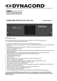
<strong>DEM</strong> <strong>314</strong> Battery Module 24V/24Ah with charging unit 24V/1A<br />
Features of the battery and charging module<br />
OWNER‘S MANUAL<br />
— 19“ - 3HU battery drawer 24V/24Ah with integrated fully automatic charging unit for continuous<br />
battery power supply.<br />
— Temperature-compensated control of charging current and charging voltage.<br />
— IU - charging characteristic<br />
— Exhaustive discharge protection<br />
— Protection against short circuit and polarity reversal<br />
— Mains failure information via floating contact<br />
— Mains and output voltage indication via LED‘s<br />
— Switchable current/voltage indication via LC display<br />
— Five individual fused outputs, AMP flat-pin plugs 6.3x0.8mm<br />
<strong>DEM</strong> <strong>314</strong><br />
24Ah/24V EMERGENCY POWER SUPPLY<br />
— Completely maintenance-free lead accumulators with VDS approval and UL certification<br />
U<br />
The specifications comply with the requirements issued by the „Leistungsgemeinschaft audio and video<br />
technology in the ZVEI.<br />
I<br />
BATTERY<br />
MAINS
CONTENTS<br />
1. Emergency power supply of alarm devices<br />
2. Commissioning of the battery and charging module<br />
2.1 Fusing of the outputs<br />
2.2 Exhaustive discharge protection<br />
2.3 Mains voltage alteration<br />
3. Instructions for the user<br />
3.1 Operation restrictions<br />
3.2 Handling instructions for the batteries<br />
3.3 Storage and additional charging<br />
3.4 Transport<br />
3.5 Battery service life<br />
3.6 Battery recycling<br />
4. Registrations and standards<br />
4.1 Battery<br />
4.2 Charging unit<br />
5. Test and inspections of alarm devices<br />
6. Glossary<br />
7. Specifications of the battery and charging module <strong>DEM</strong> <strong>314</strong><br />
8. Circuit diagrams, block diagrams<br />
WEEE Recycling/Disposal Instructions<br />
The Wheelie Bin symbol found on the product or in the manual indicates<br />
that this product must not be disposed of with other waste. It is in our<br />
category the manufacturer’s responsibility to properly dispose of their waste<br />
electrical and electronic equipment (WEEE) at the end of its life. Due to the<br />
differences in each EU country’s management of WEEE, please contact your<br />
local distributor. We are committed to facilitate our own electronic-wastemanagement-system,<br />
for the free of charge return of all EVI <strong>Audio</strong> GmbH<br />
products: Telex, Dynacord, Electro-Voice, Midas Consoles, KlarkTeknik<br />
and RTS. Arrangements are made with the dealer where you purchased the<br />
equipment from, for the returning of all unusable equipment at no cost, to the<br />
factory in Straubing, for environmental protective disposal.<br />
14
15<br />
The lightning flash with arrowhead symbol, within an<br />
equilateral triangle is intended to alert the user to the<br />
presence of uninsulated “dangerous voltage“ within the<br />
product’s enclosure that may be of sufficient magnitude<br />
to constitute a risk of electric shock to persons.<br />
The exclamation point within an equilateral triangle is<br />
intended to alert the user to the presence of important<br />
operating and maintenance (servicing) instructions in<br />
the literature accompanying the appliance.<br />
CAUTION: These servicing instructions are for use by qualified personnel only. To reduce the risk of<br />
electric shock, do not perform any servicing other than that contained in the Operating<br />
Instructions unless you are qualified to do so. Refer all servicing to qualified service personnel.<br />
1. Security regulations as stated in the EN 60065 (VDE 0860 / IEC 65) and the CSA E65 - 94 have to be obeyed when<br />
servicing the appliance.<br />
2. Use of a mains separator transformer is mandatory during maintenance while the appliance is opened, needs to be<br />
operated and is connected to the mains.<br />
3. Switch off the power before retrofitting any extensions, changing the mains voltage or the output voltage.<br />
4. The minimum distance between parts carrying mains voltage and any accessible metal piece (metal enclosure),<br />
respectively between the mains poles has to be 3 mm and needs to be minded at all times. The minimum distance<br />
between parts carrying mains voltage and any switches or breakers that are not connected to the mains (secondary<br />
parts) has to be 6 mm and needs to be minded at all times.<br />
5. Replacing special components that are marked in the circuit diagram using the security symbol (Note) is only<br />
permissible when using original parts.<br />
6. Altering the circuitry without prior consent or advice is not legitimate.<br />
7. Any work security regulations that are applicable at the location where the appliance is being serviced have to be<br />
strictly obeyed. This applies also to any regulations about the work place itself.<br />
8. All instructions concerning the handling of MOS - circuits have to be observed.<br />
NOTE:<br />
IMPORTANT SAFETY INSTRUCTIONS<br />
1. Read these instructions.<br />
2. Keep these instructions.<br />
3. Heed all warnings.<br />
4. Follow all instructions.<br />
5. Do not use this apparatus near water.<br />
6. Clean only with a dry cloth.<br />
7. Do not block any ventilation openings. Install in accordance with the manufactures instructions.<br />
8. Do not install near any heat sources such as radiators, heat registers, stoves, or other apparatus<br />
(including amplifiers) that produce heat.<br />
9. Do not defeat the safety purpose of the polarized or grounding-type plug. A polarized plug has two blades<br />
with one wider than the other. A grounding type plug has two blades and a third grounding prong. The wide<br />
blade or the third prong are provided for your safety. If the provided plug does not fit into your outlet, consult an<br />
electrican for replacement of the obsolete outlet.<br />
10. Protect the power cord from being walked on or pinched particularly at plugs, convenience receptacles,<br />
and the point where they exit from the apparatus.<br />
11. Only use attachments/accessories specified by the manufacturer.<br />
12. Unplug this apparatus during lightning storms or when unused for long periods of time.<br />
13. Refer all servicing to qualified service personnel. Servicing is required when the apparatus has been damaged<br />
in any way, such as power-supply cord or plug is damaged, liquid has been spilled or objects have fallen into the<br />
apparatus, the apparatus has been exposed to rain or moisture, does not operate normally, or has been dropped.<br />
14. Do not expose this equipment to dripping or splashing and ensure that no objects filled with liquids, such as vases,<br />
are placed on the equipment.<br />
15. To completely disconnect this equipment from the AC Mains, disconnect the power supply cord plug from the AC<br />
receptacle.<br />
16. The mains plug of the power supply cord shall remain readily operable.<br />
IMPORTANT SERVICE INSTRUCTIONS<br />
SAFETY COMPONENT ( MUST BE REPLACED BY ORIGINAL PART )
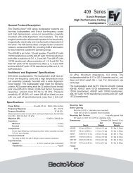
1 Ventilation holes 8 Ventilation holes<br />
2 LC display 9 Heat sink<br />
3 Switch U/I 10 Plug connector control<br />
4 LED indicator BATTERY 11 Battery outputs +24V<br />
5 LED indicator MAINS 12 Fuses for the battery outputs +24V<br />
6 Mains fuse 13 Battery outputs -24V<br />
7 Mains connector 14 Fuses for the battery outputs -24V<br />
16
1. Emergency power supply of alarm devices<br />
Alarm devices require 2 independent energy sources, both of which must be able to supply the alarm<br />
device alone. One of the energy sources must be the general mains supply or a similar network<br />
in non-stop operation. The other must be part of the apparatus (e.g. a battery) or an equivalent<br />
network fused separately. If the mains power supply is interrupted, the second source of energy must<br />
guarantee constant non-stop operation automatically and without interruption.<br />
If the energy source belonging to the alarm device consists of a battery, the user must ensure that the<br />
batteries used are suitable for stationary and floating operation.<br />
The power supply for an alarm device must not be used to supply other apparatus or parts. However,<br />
electrical equipment which serves to pass on messages may also be powered by the said source.<br />
An automatic charging device is required to charge and maintain the battery. It must be able to charge<br />
a battery which is discharged to its discharge voltage up to 80% max. of its rated capacity within 24<br />
hours.<br />
The battery capacity must be sufficient to guarantee the fixed alarm duration at the end of the stored<br />
energy time. When selecting new batteries, the user should make sure that their capacity is sufficient<br />
to compensate the capacity loss due to natural ageing of the batteries during the prescribed service<br />
life.<br />
2. Commissioning of the battery and charging module <strong>DEM</strong> <strong>314</strong><br />
Observation of the following points is essential:<br />
— The battery may only be connected to the charging unit with the mains switched off and<br />
without load (e.g. all consumers are disconnected from the battery)<br />
— The battery must be re-charged immediately after discharging. The battery must not stored<br />
in discharged status. The ability to hold a charge can no longer be reached, if the battery is<br />
stored in discharged status over a long period.<br />
— Care must be taken to ensure that the temperature in the rack is always within the allowed<br />
temperature range specified in the data sheets.<br />
— The integrated charging unit is designed for connection to 230 V AC. This can be altered to<br />
115 V AC at the mains transformer (see section 2.3 Alteration of the mains voltage). The<br />
charging unit must only be connected with a plug which has been installed correctly.<br />
— DC consumers, like power amplifiers, modules etc. are to be connected to the flat-pin plugs<br />
+24V Battery Output and -24V Battery Output. For power amplifiers there are 4 flat-pin plug<br />
outputs each, for modules (<strong>DEM</strong> 207), 1 output each.<br />
— Plug connector „Control“. For connection of the consumers with the battery in the plug<br />
connector „Control“, a link between pin 1 and 2 must be soldered. The floating contact for<br />
mains failure information is accessible at pin 7, 8 and 15 (see circuit diagram).<br />
Note: If there is no connection between pin 1 and 2 in the plug control, the unit will not function!<br />
17
2.1 Fusing of the outputs<br />
The battery has individually fused outputs to connect the consumers. Thus all departing plus and<br />
minus lines are protected against excess current and short circuits. Wires with different cross-sections<br />
for consumers with low and high current can be connected to a battery at the same time, providing<br />
the fuse values of their individual outputs are chosen accordingly. The maximum value of the fuses<br />
must not, however, exceed 20 A.<br />
The sum of the currents of all the output fuses in a fuse block must not exceed 50 A.<br />
If the fuse values are changed, the current values printed on the units above the fuse switch are to be<br />
covered with the enclosed sticky labels. The fuse values for the appropriate plus and minus outputs<br />
must always be the same.<br />
If certain outputs are not used, the fuses are to be removed and the fuse values above the fuse<br />
switches are to be covered over with the enclosed blank sticky labels.<br />
The output fused with 3 A is intended to facilitate connection of the control module <strong>DEM</strong> 207.<br />
The cross-sections of the lines connected must be correctly dimensioned for the fuse value<br />
selected. Please note that lines laid in cable channels have a lower permissible current load stability<br />
due to lower heat dissipation.<br />
The following is a guideline for bundled lines<br />
Number of lines Reduction factor<br />
2 bis 5<br />
6 bis 10<br />
16 bis 30<br />
Module type Current consumption at Ubat = 24V<br />
Standby rated power rated power<br />
-10 dB<br />
<strong>DEM</strong> 287 power amplifier 125 W<br />
<strong>DEM</strong> 288 power amplifier 250 W<br />
<strong>DEM</strong> 289 power amplifier 400W<br />
mit NRS 90 144<br />
DPA 4410 power amplifier<br />
DPA 4411 power amplifier<br />
DPA 4120 power amplifier<br />
DPA 4140 power amplifier<br />
10 mA<br />
10 mA<br />
10 mA<br />
2,5 mA<br />
60 mA<br />
2,5 mA<br />
2,5 mA<br />
2,5 A<br />
3,5 A<br />
7,0 A<br />
7,5 A<br />
7,5 A<br />
3,74 A<br />
7,1 A<br />
18<br />
5,7 A<br />
10,6 A<br />
19,7 A<br />
18 A<br />
18 A<br />
9,1 A<br />
17,3 A<br />
0.8<br />
0.7<br />
0.5<br />
Table I Fuse values of the battery outputs for connection of power amplifiers<br />
Fuse value<br />
7,5 A<br />
10 A<br />
20 A<br />
20 A<br />
20 A<br />
10 A<br />
20 A
Table II shows the maximum current which can be obtained from the battery. This must not be<br />
exceeded. This gives the maximum number of power amplifiers which can be supplied by the<br />
batteries.<br />
Battery Imax<br />
max.number of power amplifier*<br />
type in A <strong>DEM</strong> 287 <strong>DEM</strong> 288 <strong>DEM</strong> 289 DPA4410 DPA4411 DPA4120 DPA4140<br />
<strong>DEM</strong> <strong>314</strong> 50 8 4 2 2 2 5 3<br />
Table II Maximum current and number of power amplifiers<br />
* The number of power amplifiers which can be directly connected to the battery drawers can be lower<br />
than the values specified in Table II (see number of outputs, Section 7, Specifications). The values<br />
specified in the Table only refer to the connection of one amplifier type to one battery type. As long as<br />
the maximum current extracted does not exceed the value stated, however, various types of amplifier<br />
can be supplied by one type of battery.<br />
2.2 Exhaustive discharge protection<br />
The battery drawer is equipped with an exhaustive discharge protective circuit which is controlled by<br />
the battery monitoring unit in the charging device. In case of underflow of the cut-off voltage of<br />
1.75 V/cell * 12 cells = 21 V, measured at the battery poles, the consumer is disconnected from the<br />
battery and the charging unit. In this way the battery is safely protected against exhaustive discharge.<br />
If the exhaustive discharge protective circuit is activated, the red LED „low voltage“ lights up and the<br />
fault is indicated by the collective failure signal. The battery is automatically switched on again once<br />
the fault has been remedied, and the LED „low voltage“ goes out.<br />
Note: The exhaustive discharge protection only operates in conjunction with the battery modules<br />
<strong>DEM</strong>315,<strong>DEM</strong>316 and <strong>DEM</strong>317.<br />
2.3 Changing the Mains Voltage (only to be performed by qualified personnel)<br />
After beeing switched over appropriately, the battery and charging module <strong>DEM</strong> <strong>314</strong> can also be<br />
operated on 115V AC mains voltage. Switching over to accommodate the said voltage is performed as<br />
follows:<br />
— separate mains connection, control socket and all consumers from the device<br />
— remove lid<br />
— the mains transformer TR 1 - DCN 358 420 is on the left-hand side of the charging unit. To<br />
switch over to 115V AC, remove the wire jumper between solder lug 4 and 8 and solder two<br />
new wire jumpers between solder lug 2 and 4 and 8 and 10 (see fig.)<br />
230V~ 115V~<br />
19
— on the inner side of the rear wall there is a silver-coloured label with various mains voltage<br />
and fuse values. After switching over the mains voltage to 115V AC, stick the appropriate label<br />
on the outer side of the device‘s rear wall below the mains socket so that it covers the printed<br />
value 230V. Furthermore, the mains fuse T630mA must be exchanged for T1.6A. Cover the<br />
labelling of the fuse accordingly.<br />
— refit lid.<br />
3. Notes for the user<br />
3.1 Use of the battery is to be avoided in the following locations.<br />
— areas exposed to direct sunlight<br />
— areas with excessive radioactivity, infrared radiation or ultra-violet radiation<br />
— areas with organic solvent vapours, dust, salt or corrosive gases<br />
— areas with abnormal vibration.<br />
3.2 Regulations for battery use<br />
— Do not throw batteries into the fire. Do not place batteries in the proximity of fires.<br />
— Do not short battery poles.<br />
— Do not tamper with or open batteries.<br />
— If the battery has been damaged and diluted sulphuric acid comes into contact with skin or<br />
clothing, rinse immediately with plenty of water. If diluted sulphuric acid gets into the eyes,<br />
consult a doctor immediately.<br />
— Always re-charge a battery after discharging.<br />
— Never use batteries with different capacities, different degree of discharge or a mixture of old<br />
and new batteries together. The manufacturing dates should be within one month of each<br />
other.<br />
— Batteries should be stored at as low a temperature as possible. If batteries are stored at<br />
normal temperatures, one additional charging procedure is necessary once every six months.<br />
3.3 Storage and additional charging<br />
During storage the capacity is reduced due to self-discharge. The battery should be stored in a cool,<br />
dry place.<br />
If the average monthly temperature is between 20°C and 30°C, one additional charging procedure is<br />
necessary every 4 months.<br />
If a stored battery is to be used, one charging procedure should always be carried out before use.<br />
3.4 Transport<br />
Avoid excessive jolting or knocks.<br />
Remove the batteries from the housing during transport<br />
20
3.5 Battery service life<br />
Generally speaking, the battery service life in standby parallel operation amounts to 3 - 5 years and<br />
approximately 260 cycles at 100% discharge depth or more in cyclical operation. The actual service<br />
life is reduced if the appropriate operating conditions are not maintained, (i.e. charging, discharging,<br />
working temperature and storage).<br />
We recommend charging the battery at an ambient temperature of between 5°C and 35°C to minimize<br />
detrimental effects on its service life.<br />
3.6 Battery recycling<br />
The batteries are marked with a recycling symbol as illustrated below. At the end of their service life,<br />
the batteries should be returned to the manufacturer or supplier or taken to a special collection centre<br />
so that they can be recycled.<br />
4. Registrations and standards<br />
4.1 Battery<br />
— VdS registration<br />
The batteries have been tested and recognized by the VdS (Verband der Sachversicherer)<br />
and comply with the following standards:<br />
DIN 57 510 / VDE 0510 Akkumulatoren und Batterien, ortsfeste Batterien<br />
DIN 43 534 „Wartungsfreie“ verschlossene Akkumulatoren mit festgelegtem Elektrolyt<br />
DIN 43 539 part 5 Pr üfungen „wartungsfreie“ verschlossene Akkumulatoren mit festgelegtem<br />
Elektrolyt<br />
— UL approval<br />
The batteries have received recognition from the Underwriters Laboratories <strong>Inc</strong>. and have<br />
been registered under the number MH 15705.<br />
— IATA classification<br />
The batteries have been cleared by the International Air Transport Association (IATA)<br />
for transport in aircraft and have received the classification „leak-proof“.<br />
4.2 Charging unit<br />
— VDE 0871 / plot B<br />
— VDE 0860 / IEC 65<br />
21
5. Testing and inspecting alarm devices<br />
In order to gurantee that the alarm device is in working condition, qualified personnel must carry out<br />
inspections and servicing regularly.<br />
Inspections must be carried out at least once every 3 months at approximately equal intervals to<br />
comply with DIN VDE 0833 part 1.<br />
Servicing must be carried out in accordance with the manufacturer‘s instructions at least once per<br />
year.<br />
Annual servicing may be linked with the quarterly inspections if so desired, meaning that all sections of<br />
the apparatus are inspected within one year.<br />
For the battery of an alarm device this means: quarterly operational tests and annual malfunction<br />
simulations of the operating duration with the consumers.<br />
We recommend carrying out the battery capacity test in accordance with DIN 43 539 part 1, whereby<br />
the battery manufacturer‘s instructions are to be observed.<br />
Please see instructions under section 3.2 on how to treat the batteries.<br />
6. Glossary:<br />
Continuous battery power supply<br />
In this mode, the battery is constantly kept at full charge. It only gives off current if the DC<br />
source supplied by the mains fails.<br />
Nominal capacity:<br />
The nominal capacity is the value in ampere-hours for a 20-hour even, uninterrupted<br />
discharge with I20 up to the discharge voltage of 1.75 V/cell at a temperature of 25°C.<br />
Capacity:<br />
The capacity of a battery is the amount of electricity which can be extracted under the<br />
conditions in question. This depends on the discharge current, the discharge voltage and the<br />
temperature.<br />
Service life<br />
For batteries in alarm apparatus and emergency announcement systems, the end of a<br />
battery‘s service life (limit duration of operation) is reached when the capacity is less than<br />
80% of the rated capacity.<br />
Stored energy time<br />
This is the time-span between recognizing a failure in the mains supply and remedying this<br />
failure.<br />
Alarm duration<br />
The alarm duration is the time during which the alarm signal is given off.<br />
Emergency announcement duration<br />
This is the time during which announcements are made to clear the building or section of a<br />
building.<br />
22
7. Specifications <strong>DEM</strong> <strong>314</strong><br />
7.1 Battery unit<br />
Nominal voltage 24 V<br />
Discharge voltage at 25°C (1) 21 V<br />
Nominal capacity for 20 hr 24 Ah<br />
Nominal discharge current I20 1.2 A<br />
Capacity for 5 hr (2) 20 Ah<br />
Capacity for 1 hr (3) 14 Ah<br />
Capacity for 1 C (4) 12 Ah<br />
Discharge current for 5 hr (2) 4.1 A<br />
Discharge current for 1 hr (3) 14 A<br />
Discharge current for 1 C (4) 24 A<br />
Max. discharge current 50 A<br />
Standby current at mains failure 150 mA<br />
Number of outputs 5<br />
Internal resistance for 7.5 A output approx. 50 mΩ<br />
7.2 Charging unit<br />
Nominal mains voltage 230V AC 10% 50-60 Hz<br />
Nominal output voltage 24V DC<br />
Charging voltage for 2.3V/cell at 20°C 27.6V DC<br />
Nominal charging current 0.95A<br />
Max. charging current 1 .... 1.1 x In<br />
Exhaustive discharge protection/<br />
short ,circuit protection/<br />
protection against polarity reversal/<br />
I/U charging characteristic<br />
Internal temp. compensated reference<br />
Temperature coefficient of the output voltage -47mV/°C<br />
Ambient temperature +5°C .... 40°C<br />
Dimensions (WxHxD) 483 x 370 x 133 mm<br />
Weight approx. 26.6 kg with batteries<br />
8.5 kg without batteries<br />
(1) Discharge voltage at 25°C: 1.75 V/cell x 12 cells = 21.0 V<br />
(2) Capacity at 5 hours discharge with discharge current for 5 hr<br />
(3) Capacity at 1 hour discharge with discharge current for 1 hr<br />
(4) Capacity at discharge with the current in A corresponding with the nominal capacity in Ah<br />
23
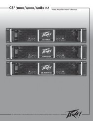
85233.1<br />
FLOATING CONTACT<br />
85233.2<br />
+24V OUTPUT<br />
NOTE 1<br />
<strong>DEM</strong> 207<br />
12V/24Ah<br />
B014<br />
CHASSIS<br />
24<br />
12V/24Ah<br />
-24V OUTPUT<br />
<strong>DEM</strong> 207<br />
NOTE 1:<br />
50A is the maximum<br />
current available from<br />
the emergency battery<br />
and must be shared by<br />
the output-pins<br />
Last modified:<br />
JUMPER BATTERY ON<br />
NO FUNCTION WITHOUT JUMPER<br />
B014<br />
CHASSIS<br />
Last plotted: 85233A
SAFETY COMPONENT<br />
(MUST BE REPLACED BY ORIGINAL PART)<br />
85234C<br />
+25.5V (3)<br />
DC VOLTAGE MEASURED WITH VOLTMETER 100kOHM/V<br />
D006<br />
B004<br />
+BATT<br />
Q004<br />
A4.1 A4 BD246 A5 A5.1<br />
R002<br />
Q001<br />
A1.1 A1 BD246 A2 A2.1<br />
40V<br />
36.3V<br />
DC VOLTAGES WITHOUT LOAD<br />
AT 230V AC LINE OPERATION<br />
+27.6V<br />
D001<br />
B006-1<br />
+BATT<br />
DC VOLTAGE MEASURED WITH VOLTMETER 100kOHM/V<br />
DC VOLTAGES WITH 1A LOAD<br />
AT 230V AC LINE OPERATION<br />
1N5401<br />
0R68<br />
R003<br />
+BATT<br />
A6<br />
1N5401<br />
D002<br />
A3<br />
470k<br />
Q003<br />
BD135<br />
R004<br />
Q002<br />
BD135<br />
C001<br />
R005<br />
R001<br />
D003<br />
16<br />
RESISTOR NOT PLACED ON BOARD<br />
R007 R006<br />
0R68<br />
A6.1<br />
0R68<br />
A3.1<br />
1N5401<br />
/250V~<br />
(1) CHARGE CURRENT
EMERGENCY BATTERY PCB<br />
BATTERY CHARGER PCB<br />
NOTE 1:<br />
50A is the maximum<br />
current available from<br />
the emergency battery<br />
and must be shared by<br />
the output-pins<br />
85233.1<br />
85233.2<br />
85234C<br />
25.5V (3)<br />
A1 A1 B1 B001<br />
B2 B002<br />
B3 B003<br />
B4 B004<br />
A2 B5 B005<br />
F001 7.5A<br />
B1.1<br />
F002 7.5A<br />
B2.1<br />
F003 7.5A<br />
B3.1<br />
F004 7.5A<br />
B4.1<br />
F005 3 A<br />
A2<br />
B5.1<br />
.E001A<br />
F011<br />
T1,6A<br />
B011<br />
.B004<br />
Q004<br />
D006 27.6V (1)<br />
A4.1 A5 BD246 A6 A5.1<br />
1N5401<br />
D001<br />
B015-2<br />
1N5401<br />
D002<br />
B015-4<br />
Q003<br />
BD135<br />
R002<br />
R003<br />
0R68<br />
R004<br />
0R68<br />
R005<br />
0R68<br />
2R2<br />
Q001<br />
A1.1 A8 BD246 A9 A2.1<br />
40.3V<br />
36.5V<br />
+BATT<br />
.B006-1<br />
MAIN TRANSFORMER<br />
TR1<br />
DCN 348 420<br />
15<br />
MAIN FUSE<br />
F1<br />
B1<br />
2<br />
T630mA<br />
+24V OUTPUT<br />
NOTE 1<br />
+BATT<br />
A7<br />
A10<br />
115V<br />
AC MAINS INPUT<br />
230V~<br />
AC 50-60 Hz<br />
470k<br />
Q002<br />
BD135<br />
C001<br />
B020<br />
R001<br />
D003<br />
16<br />
.C003<br />
(2)<br />
(1)+(3)<br />
R007 R006<br />
A6.1<br />
A3.1<br />
1N5401<br />
/250V~<br />
4<br />
C007<br />
6800µ<br />
0µ1<br />
31V<br />
U1<br />
!<br />
8<br />
100k<br />
D005<br />
470<br />
1N5401<br />
D004<br />
.E001.0<br />
344121<br />
.D001<br />
RESISTOR NOT PLACED ON BOARD<br />
ZPD39<br />
115V<br />
B014<br />
I001<br />
UC3906<br />
DSINK<br />
.B006-3<br />
12V/24Ah<br />
19<br />
10<br />
0µ1<br />
D007<br />
C/L<br />
C/SOUT<br />
C/S+<br />
4<br />
1<br />
3<br />
10k<br />
CHASSIS<br />
2.2V<br />
2.35V<br />
R010<br />
1N5401<br />
10k<br />
1N5401<br />
R021<br />
U2<br />
*<br />
13<br />
11<br />
10<br />
9<br />
7<br />
15<br />
V-SENSE<br />
C002<br />
0µ1<br />
F006 7.5A<br />
A3 A3<br />
B6.1 B6 B006<br />
F007 7.5A<br />
B7.1 B7 B007<br />
F008 7.5A<br />
B8.1 B8 B008<br />
F009 7.5A<br />
B9.1 B9 B009<br />
F010 3 A<br />
A4 A4<br />
B10.1 B10 B010<br />
V_SENS<br />
TR-BIAS<br />
SL-CONTR<br />
O-CH-IND<br />
PWR-IND<br />
DSOURCE<br />
C/S-<br />
+VIN<br />
O-CH-TER<br />
R012<br />
2R2<br />
2<br />
5<br />
8<br />
R011<br />
U3<br />
2R2<br />
R020<br />
3k9<br />
R018<br />
2k7<br />
.B001-4<br />
.B001-3<br />
.B001-2<br />
.B001-1<br />
MAIN_LED<br />
GNDA<br />
BATT_LED<br />
GNDA<br />
TO 87124 [B002]<br />
V/A-METER<br />
1N4002<br />
51k<br />
*<br />
R008<br />
27k<br />
12V/24Ah<br />
R022<br />
.D002<br />
1N4002<br />
COMP<br />
GND<br />
CH-EN<br />
LOW BATT DETECTION<br />
75k<br />
-24V OUTPUT<br />
R013<br />
1N4148<br />
D009<br />
B021<br />
F012<br />
B012<br />
B014-2<br />
B015-3<br />
B014-1<br />
B015-1<br />
.C002 .C001<br />
R015 3.8V<br />
3.2V<br />
470k<br />
5<br />
C003<br />
+<br />
R017 D012<br />
0µ1<br />
R009<br />
7<br />
-BATT .B005<br />
2.5V<br />
6<br />
10k 1N4148<br />
U2<br />
0R10<br />
-<br />
Q005<br />
U3<br />
.B003-4<br />
I002B<br />
BC337<br />
1<br />
LM358 BATT_SENS<br />
BATT_REL_ON<br />
.B003-3<br />
-BATT<br />
.B003-2<br />
-BT<br />
.B003-1<br />
R041<br />
(2) +30mV<br />
.B002-1<br />
+BATT V_SENS<br />
(1) -6mV<br />
R038<br />
100<br />
C014<br />
.B002-2<br />
+5V<br />
0V (1)+(3)<br />
(1) 420mV<br />
0µ22<br />
I004-A<br />
220k 3.8V<br />
R047 R048<br />
(2)<br />
(3) 0V<br />
.B002-3<br />
T2=55s<br />
3<br />
15<br />
+<br />
RX/CX<br />
R043<br />
14<br />
4<br />
220k 2k7<br />
C006 .B002-4<br />
C010<br />
CX #Q<br />
1<br />
6<br />
3<br />
#CLR<br />
29mV<br />
-<br />
U2<br />
2<br />
13<br />
220k R044<br />
.B002-5<br />
B Q N.C.<br />
2<br />
7<br />
I003B<br />
0µ1<br />
3<br />
47µ 1<br />
-<br />
+<br />
A<br />
I005-C<br />
I002A<br />
LM358<br />
+5V<br />
10<br />
LM358<br />
1<br />
100<br />
5<br />
R032<br />
74HC123<br />
200mV<br />
+<br />
8<br />
R046<br />
2<br />
.B003-5<br />
9<br />
-<br />
+5V<br />
1M<br />
I004-B<br />
&<br />
I005-B 74HC00<br />
I003A<br />
47k<br />
E001-O<br />
R033 9<br />
74HC00<br />
5<br />
LM358<br />
29.5V<br />
A<br />
C013<br />
.B003-7<br />
Q007<br />
5<br />
10<br />
6<br />
Q B<br />
R035<br />
BC550<br />
11<br />
#CLR<br />
4<br />
3.8V (1)<br />
1n<br />
10k<br />
12<br />
6<br />
5V (1)+(3) &<br />
#Q CX<br />
0V<br />
7<br />
51k<br />
(2)+(3)<br />
(2) 0V<br />
.B003-8<br />
RX/CX<br />
0V (2)<br />
(1)+(3) 4V<br />
C011<br />
I006-A 74HC74<br />
I005-D<br />
342069<br />
74HC123<br />
I005-A<br />
FAILURE RELAY<br />
10µ<br />
4<br />
12 &<br />
.B003-6<br />
S<br />
R049<br />
5V (2)<br />
2<br />
5<br />
2<br />
Q008<br />
D Q<br />
11<br />
R034<br />
3 13<br />
BC550<br />
Q006<br />
0V (1)+(3)<br />
T1=500ms<br />
3<br />
CLK .Q<br />
6<br />
1<br />
4k7<br />
BC550<br />
1<br />
&<br />
+5V<br />
R<br />
74HC00<br />
10k<br />
74HC00<br />
0V (1)+(2)<br />
BATT_SENS<br />
R040<br />
5V (3)<br />
14V I007 78L05<br />
D013 D014 I=13mA<br />
10k<br />
3<br />
IN OUT<br />
1<br />
+5V<br />
I006-B<br />
C016<br />
C017<br />
10<br />
1N4148 ZPD12 C015<br />
C018<br />
S<br />
12<br />
9<br />
D Q<br />
0µ33 10µ<br />
10µ 0µ1<br />
11<br />
CLK .Q<br />
8<br />
13<br />
GNDA<br />
R<br />
74HC74<br />
14<br />
6<br />
12<br />
1N4148<br />
D011<br />
15k<br />
R014<br />
T1,6A<br />
2<br />
JUMPER "BATTERY ON"<br />
10k<br />
R016<br />
NO FUNCTION<br />
WITHOUT JUMPER<br />
C004<br />
100µ<br />
D008<br />
3<br />
LM336<br />
C005<br />
47µ<br />
0µ1 0µ1<br />
B014<br />
CHASSIS<br />
TO 87124 [B001]<br />
V/A-METER<br />
+UB<br />
IN/HI(V)<br />
IN/HI(I)<br />
GNDA<br />
GNDA<br />
C012<br />
1n<br />
R037 R036<br />
26<br />
B014-15<br />
B015-5<br />
510<br />
R019<br />
10k<br />
R039<br />
1k3 220k<br />
680k<br />
820<br />
R031<br />
R030<br />
5<br />
3<br />
10k<br />
R042<br />
B014-8<br />
B015-7<br />
2k<br />
R045<br />
BATTERY FAILURE<br />
E001A<br />
1N4002<br />
D010<br />
B014-7<br />
B015-8<br />
4<br />
N.C<br />
VCC<br />
VCC<br />
VCC<br />
+UB<br />
+UB<br />
14<br />
14<br />
16<br />
8<br />
8<br />
ADJ<br />
-UB 4<br />
7<br />
GND I006-P<br />
7<br />
GND I005-P<br />
8<br />
GND I004-P<br />
-UB<br />
I002-P<br />
4<br />
I003-P<br />
2<br />
SAFETY COMPONENT<br />
(MUST BE REPLACED BY ORIGINAL PART)<br />
74HC00 74HC123<br />
LM 358 74HC74 UC 3906<br />
8 1 14 1 16<br />
78L05<br />
LM 336<br />
BC550<br />
BC337<br />
BD135<br />
BD246<br />
1<br />
XXX<br />
XXX<br />
0.4W<br />
4 5<br />
DC VOLTAGE MEASURED WITH VOLTMETER 100kOHM/V<br />
2W<br />
9<br />
8<br />
7 8<br />
1 2 3<br />
1=OUT<br />
2=GND<br />
3=IN<br />
1<br />
B E 3 2<br />
TOP VIEW!<br />
C<br />
DC VOLTAGES WITHOUT LOAD<br />
AT 230V AC LINE OPERATION<br />
E C B<br />
B C E<br />
DC VOLTAGE MEASURED WITH VOLTMETER 100kOHM/V<br />
ALTERATIONS RESERVED!<br />
DC VOLTAGES WITH 1A LOAD<br />
AT 230V AC LINE OPERATION<br />
Last modified:<br />
31.03.2005 10:36:55<br />
Last plotted: <strong>DEM</strong><strong>314</strong> 2-348504E<br />
AC VOLTAGE 50/60 HZ MEASURED VOLTMETER 2000 OHMS/V<br />
1/1<br />
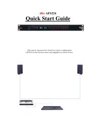
CIRCUIT DIAGRAM<br />
348 504<br />
<strong>DEM</strong> <strong>314</strong><br />
31.03.2005 12:07:19<br />
1993 DATE NAME<br />
DSG'D 28.09 Zollner<br />
Ab Ser.Nr. 12615<br />
E 013/05 21.03. MBA CHK'D<br />
D 35/99 20.12. AW APP'D<br />
C 148/96 20.11. AW<br />
B 14/94 03.02. Zolln.<br />
A 98/93 26.11. Zolln.<br />
SYMB. REVISION DATE NAME<br />
(1) CHARGE CURRENT
27<br />
1<br />
1<br />
1<br />
1<br />
1<br />
1<br />
1<br />
20 21<br />
40<br />
1 16<br />
9<br />
8<br />
E<br />
B<br />
C<br />
IN/HI(U)<br />
IN/HI(I)<br />
IN/LO<br />
+24V<br />
GND<br />
WENDELPOTI<br />
WENDELPOTI<br />
40kHz TO POWER-CHARGE PCB<br />
87124B<br />
G5<br />
23<br />
F5<br />
22<br />
E5<br />
17<br />
D5<br />
18<br />
C5<br />
19<br />
B5<br />
20<br />
A5<br />
21<br />
G4<br />
27<br />
F4<br />
26<br />
E4<br />
13<br />
D4<br />
14<br />
C4<br />
15<br />
B4<br />
24<br />
A4<br />
25<br />
G3<br />
32<br />
F3<br />
31<br />
E3<br />
9<br />
D3<br />
10<br />
C3<br />
11<br />
B3<br />
29<br />
A3<br />
30<br />
G2<br />
37<br />
F2<br />
36<br />
E2<br />
5<br />
D2<br />
6<br />
C2<br />
7<br />
B2<br />
34<br />
A2<br />
35<br />
1<br />
3<br />
Y<br />
2<br />
X<br />
39<br />
LOBAT<br />
38<br />
COMM<br />
1<br />
COL1<br />
33<br />
COL2<br />
28<br />
P1<br />
4<br />
P2<br />
8<br />
P3<br />
12<br />
P4<br />
16<br />
NC<br />
40<br />
I003<br />
R001<br />
R002<br />
S001-B<br />
S001-A<br />
Q001<br />
Q002<br />
R003<br />
R004<br />
D001<br />
C001<br />
+5V<br />
+24V<br />
R005<br />
R006<br />
R007<br />
R008<br />
R009<br />
R010 R011<br />
R012<br />
+5V<br />
+5V<br />
C003<br />
C004<br />
C005<br />
C006<br />
C007<br />
C008<br />
VR01<br />
V+<br />
1<br />
D1<br />
2<br />
C1<br />
3<br />
B1<br />
4<br />
A1<br />
5<br />
F1<br />
6<br />
G1<br />
7<br />
E1<br />
8<br />
D2<br />
9<br />
C2<br />
10<br />
B2<br />
11<br />
A2<br />
12<br />
F2<br />
13<br />
E2<br />
14<br />
D3<br />
15<br />
B3<br />
16<br />
F3<br />
17<br />
E3<br />
18<br />
AB4<br />
19<br />
POL<br />
20<br />
OSC1<br />
40<br />
OSC2<br />
39<br />
OSC3<br />
38<br />
TEST<br />
37<br />
REFHI<br />
36<br />
REFLO<br />
35<br />
C+REF<br />
34<br />
C-REF<br />
33<br />
COMMON<br />
32<br />
INHI<br />
31<br />
INLO<br />
30<br />
A-Z<br />
29<br />
BUFF<br />
28<br />
INT<br />
27<br />
V-<br />
26<br />
G2<br />
25<br />
C3<br />
24<br />
A3<br />
23<br />
G3<br />
22<br />
BP<br />
21<br />
I001<br />
VR02<br />
B001-1<br />
B001-2<br />
B001-3<br />
B001-4<br />
B001-5<br />
R013 Q003<br />
-5V<br />
R014<br />
D002<br />
D003<br />
B002-1<br />
B002-2<br />
B002-3<br />
B002-4<br />
2 3<br />
I002A<br />
4 5<br />
I002B<br />
6 7<br />
I002C<br />
10 9<br />
I002D<br />
12 11<br />
I002E<br />
15 14<br />
I002F<br />
8<br />
VCC<br />
1<br />
GND<br />
I002-P<br />
-5V<br />
D004<br />
D005<br />
C009<br />
C010<br />
+5V<br />
C011<br />
C002<br />
VI509<br />
1M<br />
1M<br />
BC550<br />
BC550<br />
10k<br />
220R<br />
C5V1<br />
22u<br />
1M<br />
47k<br />
180k<br />
330k<br />
1M<br />
1k<br />
8k2<br />
1M<br />
100n<br />
47p<br />
470n<br />
220n<br />
10n<br />
100n<br />
2k<br />
ICL7136<br />
2k<br />
1M<br />
BC550<br />
5k1<br />
MAINS<br />
BATTERY<br />
4049<br />
4049<br />
4049<br />
4049<br />
4049<br />
4049<br />
1N4148<br />
1N4148 47n<br />
100µ<br />
0µ1<br />
1n<br />
Blien<br />
<strong>DEM</strong> <strong>314</strong><br />
28.09.<br />
20.04.<br />
Zollner<br />
346 870<br />
A 98/93<br />
31.01.<br />
Zo.<br />
B 14/94 Zo.<br />
23.11.<br />
VOLT-/AMPERE-<br />
METER<br />
1993<br />
BC550 VI 509-DP-RH-W MC14049<br />
DYNACORD<br />
Last modified:<br />
Last plotted: 87124B<br />
3-<br />
nicht gespeichert!<br />
09.11.2006 12:02:47<br />
REVISION DATE NAME<br />
NAME<br />
DATE<br />
DSG'D<br />
CHK'D<br />
APP'D<br />
ALTERATIONS RESERVED!<br />
CIRCUIT DIAGRAM<br />
SYMB.<br />
1/1
Bosch Communications <strong>Systems</strong><br />
Americas–Headquarter Americas<br />
Telex Communications, <strong>Inc</strong>.<br />
12000 Portland Ave South,<br />
Burnsville, MN 55337, USA<br />
USA–Ph: 1-800-392-3497<br />
Fax: 1-800-955-6831<br />
Canada–Ph: 1-866-505-5551<br />
Fax: 1-866-336-8467<br />
Latin America–Ph: 1-952-887-5532<br />
Fax: 1-952-736-4212<br />
EVI AUDIO GmbH Subject to change without prior notice. Printed in Germany 10 /09 /2008 / D349440<br />
www.eviaudio.com<br />
Europe, Africa & Middle-East<br />
Headquarter EAME<br />
EVI <strong>Audio</strong> GmbH<br />
Hirschberger Ring 45, D-94315,<br />
Straubing, Germany<br />
Phone: +49 9421 706-0,<br />
Fax: +49 9421 706-265<br />
France: EVI <strong>Audio</strong> France S.A.,<br />
Parc de Courcerin,<br />
Allée Lech Walesa,<br />
F 77185 Lognes, France<br />
Phone: +33 1-6480-0090<br />
Fax: +33 1-6006-5103<br />
Asia & Pacific Rim–Headquarter Asia<br />
Singapore: Telex Pte. Ltd.<br />
3015A Ubi Road 1<br />
05-10 Kampong Ubi Industrial Estade<br />
Singapore 408705<br />
Phone: +(65) 6746-8760<br />
Fax: +(65) 6746-1206<br />
Japan: EVI <strong>Audio</strong> Japan Ltd.<br />
5-3-8 Funabashi, Setagaya-Ku,<br />
Tokyo, Japan 156-0055<br />
Phone: +81 3-5316-5020,<br />
Fax: +81 3-5316-5031<br />
Hong Kong: Telex EVI <strong>Audio</strong> (HK) Ltd.<br />
Unit 5,1/F, Topsail Plaza<br />
11 On Shum Street<br />
Shek Mun,Shatin HK<br />
Phone: +852 2351-3628,<br />
Fax: +852 2351-3329<br />
China: Telex EVI <strong>Audio</strong> (Shanghai) Ltd.<br />
Room 2210-2215, Tower B<br />
Far East International Plaza<br />
No. 317, Xianxia Road,<br />
Shanghai, China.<br />
Postal Code: 200051<br />
Phone: +86 21-6235-1677