EVID 12.1P User Manual - Electro-Voice
EVID 12.1P User Manual - Electro-Voice EVID 12.1P User Manual - Electro-Voice
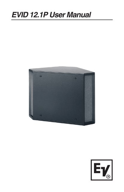
EVID 12.1P User Manual Electro-Voice ®
- Page 2 and 3: Table of Contents Product Descripti
- Page 4 and 5: Illustrated in Figure 3 are the maj
- Page 6 and 7: Step 3: Wire the Speaker A typical
- Page 8 and 9: Mounting through a suspended ceilin
- Page 10 and 11: Obtaining Warranty Service To obtai
- Page 12 and 13: Appendix C: Painting Process 10 •
- Page 14 and 15: Appendix E: Technical Specification
- Page 16: U.S.A. and Canada: For customer ord
<strong>EVID</strong> <strong>12.1P</strong> <strong>User</strong> <strong>Manual</strong><br />
<strong>Electro</strong>-<strong>Voice</strong> ®
Table of Contents<br />
Product Description ................................................................................. 1<br />
Product Feature Identification .................................................................. 1<br />
Packing List ............................................................................................. 2<br />
Step-by-Step Installation and Wiring ........................................................ 3<br />
Step 1: Mount the Bracket ................................................................. 3<br />
Step 2: Install the Safety Line ............................................................ 3<br />
Step 3: Wire the Speaker .................................................................. 4<br />
Step 4: Mount the Speaker to the Bracket ......................................... 4<br />
For Corner Mounting ................................................................... 4<br />
For Midwall Mounting .................................................................. 5<br />
Mounting through a Suspended Ceiling Grid............................... 6<br />
Floor Mounting ............................................................................ 6<br />
Step 5: Test System Operation .......................................................... 6<br />
Safety Agency Compliance ...................................................................... 7<br />
Maintenance ............................................................................................ 7<br />
Appendix A: Warranty Statement ............................................................. 7<br />
Appendix B: Installation Examples ........................................................... 8<br />
Characteristics of all Subwoofers ...................................................... 9<br />
Appendix C: Painting Process ............................................................... 10<br />
Appendix D: Troubleshooting ................................................................. 11<br />
Appendix E: Technical Specifiations ...................................................... 12<br />
TOC<br />
<strong>Electro</strong>-<strong>Voice</strong> ®
Product Description<br />
The <strong>12.1P</strong> is a self contained, powered 12" subwoofer providing over<br />
300 watts continuous output to the speaker. The <strong>12.1P</strong> makes the<br />
addition of a subwoofer to a <strong>EVID</strong> system very easy and efficient. Since<br />
the unit is self-powered, the full range satellite speakers can be powered<br />
independently from the subwoofer and optimized for the installation.<br />
The <strong>12.1P</strong> features a high performance, variable, 12-dB/octave<br />
crossover and a full range line level output along with a high pass line<br />
level output on the rear panel. The unit can be mounted in a variety of<br />
configurations with the bracket hardware supplied.<br />
Product Feature Identification<br />
The <strong>12.1P</strong> subwoofer comes with a dual-mode mounting bracket that<br />
enables the unit to be easily mounted at either a wall/wall (corner) or on<br />
a wall/ceiling (midwall) junction. The included forged steel eyebolt<br />
provides the installer a solid attachment point for a safety line. When<br />
properly anchored and supported, the <strong>12.1P</strong> subwoofer may also be<br />
safely installed protruding just 2 3/4" down through a standard suspended<br />
ceiling grid. See installation instructions.<br />
Dual-mode<br />
mounting<br />
bracket<br />
EV ®<br />
logo<br />
Acoustic<br />
ports<br />
Figure 1: <strong>EVID</strong> TM <strong>12.1P</strong> Features<br />
(Front)<br />
<strong>Electro</strong>-<strong>Voice</strong> ® <br />
Amplifier<br />
panel<br />
Safety line<br />
attachment<br />
eyebolt<br />
Bracket clip<br />
mounting<br />
points<br />
Figure 2: <strong>EVID</strong> TM <strong>12.1P</strong> Features<br />
(Rear)<br />
1
Illustrated in Figure 3 are the major<br />
components of the <strong>EVID</strong> TM <strong>12.1P</strong><br />
subwoofer amplifier.<br />
Packing List<br />
2<br />
A. Variable Crossover Control<br />
B. High Pass XLR Line Level Output<br />
C. Full Range XLR Line Level Output<br />
D. Power Switch<br />
E. AC Line Cord Connector<br />
Below is a list of parts included with<br />
the <strong>EVID</strong> TM <strong>12.1P</strong> subwoofer. The<br />
parts are illustrated in Figure 4.<br />
A. <strong>EVID</strong>TM <strong>12.1P</strong><br />
B. Wall/Corner Mounting Bracket<br />
C. (4) Rubber Mounting Feet<br />
D. (2) Speaker Mounting Clips<br />
E. Eyebolt<br />
F. Right Angle Power Cord<br />
G. Owner’s <strong>Manual</strong><br />
H. Warranty Card<br />
Figure 4: <strong>EVID</strong> TM <strong>12.1P</strong> Packing List<br />
A<br />
C<br />
D<br />
B<br />
D<br />
E<br />
C<br />
Figure 3: <strong>EVID</strong> TM <strong>12.1P</strong><br />
Amplifer Panel<br />
E G<br />
<strong>Electro</strong>-<strong>Voice</strong> ® <br />
H<br />
B<br />
A<br />
F
Step-by-Step Installation & Wiring<br />
Step 1: Mount the Bracket<br />
The mounting bracket can be installed two ways (see Figures 5 and 6),<br />
allowing optimal configurations for installations. Leave 1.5" of space<br />
between the bracket and the ceiling when installing in a corner! Attach<br />
the bracket to the wall with suitable fasteners screwed into structural<br />
members in the wall. Remember: It is the installer’s responsibility to<br />
insure that the structure can safely support the load.<br />
Use a<br />
mimimum of<br />
four screws<br />
Wall<br />
Bracket<br />
Stud<br />
Wall<br />
Figure 5: Corner Installation<br />
(Top View)<br />
Step 2: Install the Safety Line<br />
Using accepted safe rigging practices, secure one end of a suitable<br />
safety line (use cable, not chain, which will rattle) to a strong, secure<br />
point above the speaker, a point that can withstand the shock of the<br />
falling speaker. This is especially important in public spaces constructed<br />
with light gauge steel studs. Do not attach the safety line to the bracket!<br />
The safety line should prevent the speaker from falling if the bracket<br />
tears loose from the wall. Secure the other end to the eyebolt that is fully<br />
threaded into the enclosure.<br />
<strong>Electro</strong>-<strong>Voice</strong> ® <br />
Stud<br />
Use a<br />
mimimum of<br />
four screws<br />
Joist<br />
Ceiling Bracket<br />
Wall<br />
Figure 6: Midwall Installation<br />
(Side View)<br />
Top<br />
plate<br />
Stud<br />
3
Step 3: Wire the Speaker<br />
A typical wiring configuration is shown in Figure 7. It is highly advisable<br />
to support the unit while these connections are being made. When<br />
mounting the speaker in a corner mount configuration, a right angle XLR<br />
connector such as Neutrik #NC3MRC or equiv. is required for the signal<br />
connections (see Figure 7). Connect the line level signal from the mixer,<br />
pre amplifier or other source into the line input connector. Plug in the<br />
power cord and connect the unit to a standard 120VAC power source.<br />
The proper crossover setting is<br />
determined by the satellite<br />
speakers used. The following<br />
are general guidelines:<br />
4<br />
Figure 7: Wiring Configuration<br />
Adjust the crossover according<br />
to the chart above. Set the<br />
appropriate sub level before<br />
making the final mounting to the<br />
bracket.<br />
Step 4: Mount the Speaker to the Bracket<br />
First remove the two Phillips-head screws on the rear of the enclosure.<br />
Use the supplied eyebolt to mount one mounting clip to the top of the<br />
speaker as shown in Figure 8. Check to make sure that the wiring<br />
connections to the amplifier and the satellite speakers are correct and<br />
secure.<br />
For corner mounting<br />
Sate<br />
llite<br />
Spe<br />
aker<br />
Cro<br />
sso<br />
ver<br />
Settin<br />
g<br />
3. 2<br />
110<br />
Hz<br />
4. 2<br />
95<br />
Hz<br />
6. 2<br />
80<br />
Hz<br />
Attach the four rubber mounting feet to the front side edges, and secure<br />
the safety line to the eyebolt. Lift the enclosure up to the ceiling and<br />
center it back it into the corner until it touches the bracket rungs, then<br />
carefully lower it so the top clip hooks over the top rung of the bracket<br />
(1). Insert one of the 3/8-16-thread Phillips-head screws through the<br />
remaining clip and, with the clip pointing up, thread the screw finger-tight<br />
into the lower mtg. hole on the enclosure (2, 3). Level the clip and tighten<br />
securely with a #3 right-angle Phillips screwdriver. Even though the<br />
<strong>Electro</strong>-<strong>Voice</strong> ®
enclosure hangs from the top clip, always install the lower one to secure<br />
against possible disengagement of the top clip. Straighten the EV® logo<br />
and press firmly at its center to seat it securely into its mounting hole.<br />
For midwall mounting<br />
3<br />
1<br />
Rungs<br />
2<br />
Figure 8: Corner Mounting Figure 9: Midwall Mounting<br />
Attach the four rubber mounting feet inside the corners on the side of the<br />
enclosure that will be against the wall and attach the safety line to the<br />
eyebolt. Insert one of the 3/8-16-thread Phillips-head screws through the<br />
remaining clip and keep it within arm’s reach. Lift the enclosure up to the<br />
ceiling and bring its back into contact with the bracket rungs. Slide the<br />
enclosure sideways to engage the clip over one bracket rung (1) and,<br />
while holding it tight against both rungs, insert the 3/8-16-thread screw<br />
with its clip into the remaining mounting hole so the clip engages the<br />
remaining bracket rung (2, 3). Finger-tighten the screw and straighten<br />
the clip. The enclosure may now be released. It will slide down the rungs<br />
until the four rubber feet are snug against the wall. Using a #3 right-angle<br />
Phillips screwdriver, securely tighten the second Phillips-head screw.<br />
Gently rotate the EV® logo a quarter turn and press firmly at its center to<br />
seat it securely into its mounting hole. See Figure 9.<br />
<strong>Electro</strong>-<strong>Voice</strong> ® 5<br />
1<br />
Rungs<br />
This side towards wall<br />
2<br />
3
Mounting through a suspended ceiling grid<br />
On the rear of the enclosure install and tighten two 3/8-16-thread forged<br />
steel eyebolts (one is included) with a 3/8" flat washer under each. Cut<br />
two pieces of ordinary drop ceiling L angle (wall track) 23 3/4" long and<br />
screw them to the top and bottom of the enclosure with 3/4"-long sheet<br />
metal screws, as shown in Figure 10. Connect all of the wires and<br />
suspend the enclosure, face down, by the eyebolts in accordance with<br />
accepted safe rigging practice. Adjust the length of the rigging cables so<br />
the tips of the installed L angles just rest on the ceiling cross-tees. This<br />
stabilizes the enclosure from rocking. Trim the ceiling panel to fit the new<br />
opening(s) and drop into place. It is the installer’s responsibility to assure<br />
that the chosen rigging points are strong enough to support the load.<br />
Floor Mounting<br />
6<br />
Warning: Never try to install this speaker in a suspended<br />
ceiling without proper rigging support!<br />
Rigging<br />
cables<br />
L angle Ceiling<br />
tile<br />
Eyebolts<br />
Acoustic port<br />
Figure 10: Attach L Angles to Speaker<br />
The <strong>EVID</strong> <strong>12.1P</strong> may be placed directly on the floor in a corner or on<br />
its side along a straight wall by simply attaching the four rubber mounting<br />
feet to the side that will sit on the floor.<br />
Step 5: Test System Operation<br />
After all connections are made test the complete system operation.<br />
Appendix C on page 10 contains a troubleshooting guide to assist in<br />
locating a variety of speaker related problems.<br />
<strong>Electro</strong>-<strong>Voice</strong> ®
Safety Agency Compliance<br />
The <strong>EVID</strong> <strong>12.1P</strong> bracket system has successfully passed EIA 636 at a<br />
safety factor of 6:1. The bracket system is intended to support the<br />
<strong>EVID</strong> <strong>12.1P</strong> only. Do not use it for any other purpose. Never set<br />
anything on, or hang anything from, the <strong>EVID</strong> <strong>12.1P</strong> enclosure when<br />
using this bracket. For a copy of the model-specific CE Declaration of<br />
Conformity, contact <strong>Electro</strong>-<strong>Voice</strong> at the address listed at the end of this<br />
manual.<br />
Maintenance<br />
Your <strong>EVID</strong> system has been designed and manufactured to provide<br />
years of durability and reliable service. No routine maintenance is<br />
necessary. Units may be cleaned by wiping with a soft, damp cloth.<br />
Never use solvents or harsh cleaning agents of any kind.<br />
Appendix A: Warranty Statement<br />
<strong>Electro</strong>-<strong>Voice</strong>® Speakers and Speaker Systems are guaranteed against<br />
malfunction due to defects in materials or workmanship for a period of<br />
five (5) years from the date of original purchase. The Limited Warranty<br />
does not apply to burned voice coils or malfunctions such as cone and/or<br />
coil damage resulting from improperly designed enclosures. <strong>Electro</strong>-<br />
<strong>Voice</strong>® active electronics associated with the speaker systems are<br />
guaranteed for three (3) years from the date of original purchase.<br />
If such malfunction occurs during the specified period, the product will be<br />
repaired or replaced (at our discretion) without charge. The product will<br />
be returned to the customer prepaid.<br />
Exclusions and Limitations<br />
The Limited Warranty does not apply to: (a) exterior finish or<br />
appearance; (b) certain specific items described in the individual<br />
product-line statements below, or in the individual product sheet or<br />
owner’s manual; (c) malfunction resulting from use or operation of the<br />
product other than as specified in the product data sheet or owner’s<br />
manual; (d) malfunction resulting from misuse or abuse of the product;<br />
or (e) malfunction occurring at any time after repairs have been made to<br />
the product by anyone other than <strong>Electro</strong>-<strong>Voice</strong>® Service or any of its<br />
authorized representatives.<br />
<strong>Electro</strong>-<strong>Voice</strong> ® 7
Obtaining Warranty Service<br />
To obtain warranty service, a customer must deliver the product, prepaid,<br />
to <strong>Electro</strong>-<strong>Voice</strong>® Service or to any of its authorized service<br />
representatives, together with proof of purchase of the product in the<br />
form of a bill of sale or receipted invoice. A list of authorized service<br />
representatives is available from <strong>Electro</strong>-<strong>Voice</strong>® Service at:<br />
12000 Portland Avenue,<br />
Burnsville, MN 55337<br />
Ph: (877) 863-4166<br />
Incidental and Consequential Damages<br />
Excluded<br />
Product repair or replacement and return to the customer are the only<br />
remedies provided to the customer. <strong>Electro</strong>-<strong>Voice</strong>® shall not be liable for<br />
any incidental or consequential damages including, without limitation,<br />
injury to persons or property or loss of use. Some states do not allow the<br />
exclusion or limitation of incidental or consequential damages, so the<br />
above limitation or exclusion may not apply to you.<br />
Other Rights<br />
This warranty gives you specific legal rights, and you may also have<br />
other rights which vary from state to state.<br />
Appendix B: Installation<br />
Examples<br />
The <strong>EVID</strong> Series is a product family with the flexibility to fit the<br />
requirements of many different applications. Listed below are some<br />
suggested combinations for systems using the <strong>12.1P</strong> with <strong>EVID</strong> full<br />
range speakers:<br />
• Rich, full-sounding low-level background music and paging in a<br />
quiet restaurant, office, or retail space: use two <strong>EVID</strong> 3.2’s or<br />
C4.2’s for each <strong>12.1P</strong> installed.<br />
8<br />
• Moderate-level music and paging in a sports bar/restaurant or<br />
upbeat retail space: install two or four <strong>EVID</strong> 4.2’s or C8.2’s for<br />
each <strong>12.1P</strong> used.<br />
<strong>Electro</strong>-<strong>Voice</strong> ®
• Higher-level foreground music in bass heavy applications such<br />
as dance floors, amusement arcades, or loud bars: use one pair<br />
of <strong>EVID</strong> 6.2’s for each <strong>12.1P</strong>.<br />
• For example, a large hotel might use eight 3.2’s and two <strong>12.1P</strong>’s<br />
in the dining room, eight 4.2’s and two <strong>12.1P</strong>’s in the lounge, four<br />
6.2’s with two <strong>12.1P</strong>’s surrounding the dance floor, 6.2’s around<br />
the pool, 6.2’s or 4.2s with or without <strong>12.1P</strong>’s in the lobby, and<br />
3.2’s in the corridors.<br />
Characteristics of All Subwoofers<br />
While subwoofers do radiate sound omni-directionally (in all directions)<br />
and the sound is generally non-localizable (one can’t hear exactly where<br />
it comes from), subwoofer sound level still drops off the farther one<br />
moves from the subwoofer. The highest output and best room loading<br />
are accomplished with the subwoofer mounted in a corner at a threeboundary<br />
junction (wall/wall/ceiling or wall/wall/floor, an arrangement<br />
also referred to as 1/8 space). Mounting at a two-boundary junction (wall/<br />
ceiling, or 1/4 space) produces three dB less output, and mounting in the<br />
middle of a room in the ceiling (1/2 space) reduces output still another<br />
three dB.<br />
Subwoofers produce large amounts of long wavelength low-frequency<br />
energy. Every object has its own resonant frequency, and long<br />
wavelengths tend to excite large objects (like walls, floors, doors and<br />
ceiling panels). Anything loose in or on a ceiling or wall will buzz or rattle<br />
as a subwoofer’s level is increased. Most of these can be isolated and<br />
fixed with small, strategically placed bits of foam tape. Others may<br />
require driving additional nails or screws and perhaps some caulking to<br />
dampen their sympathetic movement.<br />
<strong>Electro</strong>-<strong>Voice</strong> ® 9
Appendix C: Painting Process<br />
10<br />
• Remove the four screws securing the front hatch and lift off the<br />
hatch panel. Carefully twist and lift off the EV® logo and set it<br />
aside.<br />
• The foam grille blocks are held in place by sharp pins protruding<br />
through the baffle board. Note the relative position of the foam<br />
and carefully lift the blocks off the pins. Mask around and over<br />
the amplifier panel with tape and heavy paper and tape a piece<br />
of heavy paper over the woofer. It is not necessary to remove<br />
any components.<br />
• Clean the cabinet, bracket and clips by rubbing with a lightly<br />
dampened cloth. Do not use abrasives such as sandpaper or<br />
steel wool. Never use gasoline, kerosene, acetone, MEK, paint<br />
thinner, harsh detergents, or other chemicals, as these agents<br />
may cause permanent damage to the enclosure.<br />
• After cleaning, apply two or more two thin coats of either latex or<br />
oil-based paint. Spraying is recommended, but a brush and<br />
small roller work very well. It is not necessary to paint all the way<br />
up to the woofer. Only the visible surfaces need to be painted:<br />
the hatch front and side edges, the exposed enclosure surfaces<br />
down to the hatch gaskets and about halfway under where the<br />
foam blocks sit. Likewise, the rear sides of the bracket and clips<br />
need not be painted. The hatch screw heads may be painted, if<br />
desired.<br />
• When the paint is thoroughly dry, carefully unmask everything.<br />
Replace the foam blocks, pressing them gently down onto the<br />
sharp pins. Replace the hatch cover and tighten the four screws.<br />
Locate the small center hole, properly orient the EV® logo, and<br />
press it firmly into place at its center to reseat it in the mounting<br />
hole.<br />
<strong>Electro</strong>-<strong>Voice</strong> ®
Appendix D: Troubleshooting<br />
Guide<br />
Problem Possible Cause(s) Action<br />
1. No sound Amplifier Verify that that the line level signal cable’s<br />
XLR connector has been pushed all the way<br />
into the ‘Low Level In’ jack on the amplifier<br />
panel. Turn the ‘Power’ switch on and the<br />
volume up until you can hear sound emitting<br />
from the 12.1p subwoofer. If there is still no<br />
sound, the problem is with the line level<br />
signal.<br />
Line level signal Connect a known working powered test<br />
speaker to the line level signal from the<br />
mixer, pre amplifier or other source. If there<br />
is no sound, check that all of the electronics<br />
are on, the signal routing is correct, the<br />
source is active, the volume is on and so on.<br />
Fuse Carefully remove the fuse holder from the<br />
power cord input with the use of a flat head<br />
screwdriver. Inspect the fuse for any<br />
damage. Blown fuses will typically show a<br />
smoke-like blackening on the inside of the<br />
glass. If this is the problem, replace the fuse<br />
with a 4A/250V, 20mm x 5mm fuse.<br />
Only replace this fuse with the same type<br />
and rated fuse to reduce the risk of fire.<br />
2. Poor low-frequency Speakers wired When two speakers are connected out<br />
response out-of-polarity of polarity (out of phase), the low frequencies<br />
will cancel each other acoustically. Carefully<br />
observe the wire markings or tracers on your<br />
full-range speaker wires. Verify that their<br />
amplifier (+) terminal is connected to the red<br />
speaker terminals and their amplifier (-)<br />
terminal is connected to the black speaker<br />
terminals.<br />
3. Intermittent output Faulty Check the low-level signal cable/XLR<br />
such as crackling or connection/wiring connector to make sure that it has been<br />
distortion pushed all the way into the ‘Low Level In’<br />
amplifier panel jack. If crackling persists,<br />
remove the signal cable from the amplifier<br />
and its low-level signal source and check for<br />
a faulty connection between the connector<br />
and the cable. Make sure that all of the<br />
terminals on cable connectors have been<br />
properly soldered.<br />
<strong>Electro</strong>-<strong>Voice</strong> ® If these suggestions do not solve your problem, contact your nearest <strong>Electro</strong>-<strong>Voice</strong><br />
dealer or <strong>Electro</strong>-<strong>Voice</strong> distributor.<br />
11
Appendix E: Technical<br />
Specifications<br />
Frequency Response (-10 dB): 42 Hz – 160 Hz<br />
Max Calculated SPL 1 @ 1M: 126 dB<br />
LF Amplifier Power: 650W 50ms Burst, 300W<br />
Continuous<br />
Line Input Sensitivity: -12 dBu to 0 dBu for Full Output<br />
LF Transducer: 12” (300 mm) High-Excursion Dual<br />
<strong>Voice</strong>-Coil<br />
Connectors:<br />
Line Inputs: XLR<br />
Balanced Outputs: XLR<br />
Power Requirement: 110-130 VAC, 50-60 Hz<br />
Enclosure Material: MDF, Steel Fastener Reinforced<br />
Included Accessories: Mounting Bracket and Hardware<br />
Dim (H x W x D): 16.25" x 23.0" x 12.0"<br />
(412 mm x 584 mm x 305 mm)<br />
Net Weight: 49.0 lbs (22.2 kg)<br />
12<br />
1 1/8 Space (Corner Mounting) @ 1 Meter<br />
<strong>Electro</strong>-<strong>Voice</strong> ®
Notes<br />
<strong>Electro</strong>-<strong>Voice</strong> ® 13
U.S.A. and Canada:<br />
For customer orders, contact the Customer Service department at:<br />
800/392-3497 Fax: 800/955-6831<br />
For warranty repair or service information, contact the Service Repair Department at:<br />
800/685-2606<br />
For technical assistance, contact Technical Support at:<br />
866/78-AUDIO<br />
Specifications subject to change without notice.<br />
All Other International Locations:<br />
952-884-4051 Fax: 952-736-4212<br />
www.electrovoice.com l Telex Communications, Inc. l www.telex.com<br />
Printed in U.S.A<br />
© Telex Communications, Inc. 2/2003<br />
Part Number 38110-199 Rev A<br />
<strong>Electro</strong>-<strong>Voice</strong> ®


