
You also want an ePaper? Increase the reach of your titles
YUMPU automatically turns print PDFs into web optimized ePapers that Google loves.
® ®<br />
Complete Equalization & Loudspeaker Control System<br />
<strong>PA</strong><br />
Featuring<br />
Custom Tunings<br />
®<br />
User <strong>Manual</strong>
IMPORTANT SAFETY INSTRUCTIONS<br />
SAFETY INSTRUCTIONS<br />
NOTICE FOR CUSTOMERS IF YOUR UNIT IS EQUIPPED WITH A POWER CORD.<br />
WARNING: THIS APPLIANCE MUST BE EARTHED.<br />
CAUTION<br />
RISK OF ELECTRIC SHOCK<br />
DO NOT OPEN<br />
ATTENTION: RISQUE DE CHOC ELECTRIQUE - NE <strong>PA</strong>S OUVRIR<br />
WARNING: TO REDUCE THE RISK OF FIRE OR ELECTRIC<br />
SHOCK DO NOT EXPOSE THIS EQUIPMENT TO RAIN OR MOISTURE<br />
The symbols shown above are internationally accepted symbols that warn of potential hazards with<br />
electrical products. The lightning flash with arrowpoint in an equilateral triangle means that there<br />
are dangerous voltages present within the unit. The exclamation point in an equilateral triangle indicates<br />
that it is necessary for the user to refer to the owner’s manual.<br />
These symbols warn that there are no user serviceable parts inside the unit. Do not open the unit.<br />
Do not attempt to service the unit yourself. Refer all servicing to qualified personnel. Opening the<br />
chassis for any reason will void the manufacturer’s warranty. Do not get the unit wet. If liquid is<br />
spilled on the unit, shut it off immediately and take it to a dealer for service. Disconnect the unit during<br />
storms to prevent damage.<br />
The cores in the mains lead are coloured in accordance with the following code:<br />
GREEN and YELLOW - Earth BLUE - Neutral BROWN - Live<br />
As colours of the cores in the mains lead of this appliance may not correspond with the coloured markings<br />
identifying the terminals in your plug, proceed as follows:<br />
• The core which is coloured green and yellow must be connected to the terminal in the plug<br />
marked with the letter E, or with the earth symbol, or coloured green, or green and yellow.<br />
• The core which is coloured blue must be connected to the terminal marked N or coloured black.<br />
• The core which is coloured brown must be connected to the terminal marked L or coloured red.<br />
This equipment may require the use of a different line cord, attachment plug, or both, depending on the<br />
available power source at installation. If the attachment plug needs to be changed, refer servicing to qualified<br />
service personnel who should refer to the table below. The green/yellow wire shall be connected<br />
directly to the units chassis.<br />
CONDUCTOR<br />
WIRE COLOR<br />
Normal Alt<br />
L LIVE BROWN BLACK<br />
N NEUTRAL BLUE WHITE<br />
E EARTH GND GREEN/YEL GREEN<br />
WARNING: If the ground is defeated, certain fault conditions in the unit or in the system to which it is connected<br />
can result in full line voltage between chassis and earth ground. Severe injury or death can then<br />
result if the chassis and earth ground are touched simultaneously.<br />
KEEP THESE INSTRUCTIONS<br />
HEED ALL WARNINGS<br />
FOLLOW ALL INSTRUCTIONS<br />
WARNING FOR YOUR PROTECTION<br />
PLEASE READ THE FOLLOWING:<br />
THE AP<strong>PA</strong>RATUS SHALL NOT BE EXPOSED TO DRIPPING OR SPLASHING LIQUID AND NO OBJECT<br />
FILLED WITH LIQUID, SUCH AS VASES, SHALL BE PLACED ON THE AP<strong>PA</strong>RATUS.<br />
CLEAN ONLY WITH A DRY CLOTH.<br />
DO NOT BLOCK ANY OF THE VENTILATION OPENINGS. INSTALL IN ACCORDANCE WITH THE<br />
MANUFACTURER’S INSTRUCTIONS.<br />
DO NOT INSTALL NEAR ANY HEAT SOURCES SUCH AS RADIATORS, HEAT REGISTERS, STOVES,<br />
OR OTHER AP<strong>PA</strong>RATUS (INCLUDING AMPLIFIERS) THAT PRODUCE HEAT.<br />
ONLY USE ATTACHMENTS/ACCESSORIES SPECIFIED BY THE MANUFACTURER.<br />
UNPLUG THIS AP<strong>PA</strong>RATUS DURING LIGHTNING STORMS OR WHEN UNUSED FOR LONG PERI-<br />
ODS OF TIME.<br />
Do not defeat the safety purpose of the polarized or grounding-type plug. A polarized plug<br />
has two blades with one wider than the other. A grounding type plug has two blades and<br />
a third grounding prong. The wide blade or third prong are provided for your safety. If<br />
the provided plug does not fit your outlet, consult an electrician for replacement of the<br />
obsolete outlet.<br />
Protect the power cord from being walked on or pinched particularly at plugs, convenience<br />
receptacles, and the point where they exit from the apparatus.<br />
Use only with the cart stand, tripod bracket, or table specified by the manufacture, or sold<br />
with the apparatus. When a cart is used, use caution when moving the cart/apparatus<br />
combination to avoid injury from tip-over.<br />
Refer all servicing to to qualified service personnel. Servicing is required when the apparatus<br />
has been damaged in any way, such as power-supply cord or plug is damaged, liquid<br />
has been spilled or objects have fallen into the apparatus, the apparatus has been<br />
exposed to rain or moisture, does not operate normally, or has been dropped.<br />
POWER ON/OFF SWITCH: The Power switch used in this piece of equipment DOES NOT break<br />
the connection from the mains.<br />
MAINS DISCONNECT: The plug shall remain readily operable. For rack-mount or installation<br />
where plug is not accessible, an all-pole mains switch with a contact separation of at<br />
least 3 mm in each pole shall be incorporated into the electrical installation of the rack or<br />
building.<br />
FOR UNITS EQUIPPED WITH EXTERNALLY ACCESSIBLE FUSE RECEPTACLE: Replace fuse with<br />
same type and rating only.<br />
MULTIPLE-INPUT VOLTAGE: This equipment may require the use of a different line cord,<br />
attachment plug, or both, depending on the available power source at installation. Connect<br />
this equipment only to the power source indicated on the equipment rear panel. To reduce<br />
the risk of fire or electric shock, refer servicing to qualified service personnel or equivalent.<br />
This Equipment is intended for rack mount use only.
IMPORTANT SAFETY INSTRUCTIONS<br />
LITHIUM BATTERY<br />
WARNING<br />
CAUTION!<br />
This product may contain a lithium battery.There is danger of<br />
explosion if the battery is incorrectly replaced. Replace only<br />
with an Eveready CR 2032 or equivalent. Make sure the battery<br />
is installed with the correct polarity. Discard used batteries<br />
according to manufacturer’s instructions.<br />
ADVARSEL!<br />
Lithiumbatteri - Eksplosjonsfare.Ved utskifting benyttes kun<br />
batteri som anbefalt av apparatfabrikanten. Brukt batteri<br />
returneres apparatleverandøren.<br />
ADVARSEL!<br />
Lithiumbatteri - Eksplosionsfare ved fejlagtig håndtering.<br />
Udskiftning må kun ske med batteri av samme fabrikat og<br />
type. Levér det brugte batteri tilbage til leverandøren.<br />
VAROITUS!<br />
Paristo voi räjähtää, jos se on virheellisesti asennettu.Vaihda<br />
paristo ainoastaan laitevalmistajan suosittelemaan tyyppin.<br />
Hävitä käytetty paristo valmistajan ohjeiden mukaisesti.<br />
VARNING!<br />
Explosionsfara vid felaktigt batteribyte.Använd samma batterityp<br />
eller en ekvivalent typ som rekommenderas av apparattillverkaren.<br />
Kassera använt batteri enligt fabrikantens instruktion.<br />
ELECTROMAGNETIC<br />
COM<strong>PA</strong>TIBILITY<br />
This unit conforms to the Product<br />
Specifications noted on the Declaration of<br />
Conformity. Operation is subject to the following<br />
two conditions:<br />
• this device may not cause harmful interference,<br />
and<br />
• this device must accept any interference<br />
received, including interference that may<br />
cause undesired operation.<br />
Operation of this unit within significant electromagnetic<br />
fields should be avoided.<br />
• use only shielded interconnecting cables.<br />
U.K. MAINS PLUG WARNING<br />
A molded mains plug that has been cut off from the cord is unsafe. Discard the<br />
mains plug at a suitable disposal facility. NEVER UNDER ANY CIRCUMSTANCES<br />
SHOULD YOU INSERT A DAMAGED OR CUT MAINS PLUG INTO A 13 AMP<br />
POWER SOCKET. Do not use the mains plug without the fuse cover in place.<br />
Replacement fuse covers can be obtained from your local retailer. Replacement<br />
fuses are 13 amps and MUST be ASTA approved to BS1362.<br />
DECLARATION OF<br />
CONFORMITY<br />
Manufacturer’s Name: dbx Professional Products<br />
Manufacturer’s Address: 8760 S. Sandy Parkway<br />
Sandy, Utah 84070, USA<br />
declares that the product:<br />
Product name: dbx DriveRack <strong>PA</strong><br />
Note: Product name may be suffixed by the EU.<br />
Product option: None<br />
conforms to the following Product Specifications:<br />
Safety: IEC 60065 (1998)<br />
EMC: EN 55013 (1990)<br />
EN 55020 (1991)<br />
Supplementary Information:<br />
The product herewith complies with the requirements of the<br />
Low Voltage Directive 72/23/EEC and the EMC Directive<br />
89/336/EEC as amended by Directive 93/68/EEC.<br />
Vice-President of Engineering<br />
8760 S. Sandy Parkway<br />
Sandy, Utah 84070, USA<br />
Date: April 19,2002<br />
European Contact: Your local dbx Sales and Service Office or<br />
Harman Music Group<br />
8760 South Sandy Parkway<br />
Sandy, Utah 84070 USA<br />
Ph: (801) 566-8800<br />
Fax: (801) 568-7583
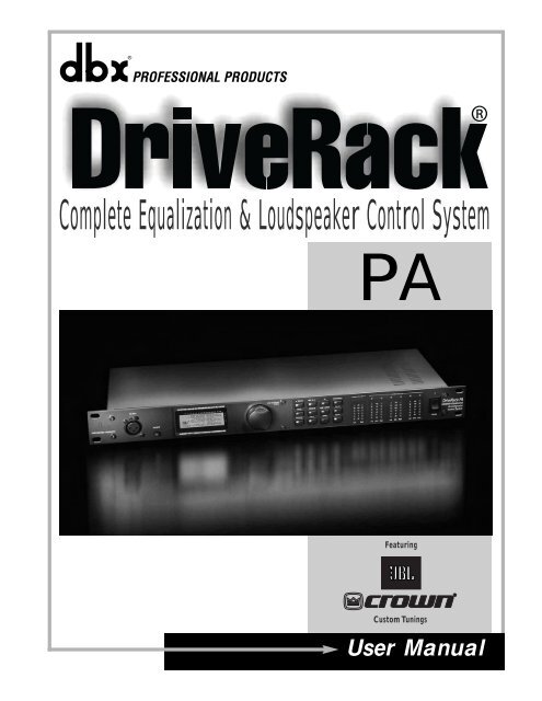
DriveRack ®<br />
<strong>PA</strong><br />
Introduction<br />
0.1 Defining the DriveRack ® <strong>PA</strong> .........................ii<br />
0.2 Service Contact Info........................................iii<br />
0.3 Warranty...........................................................iv<br />
Section 1 - Getting Started<br />
1.1 Rear Panel ......................................................2<br />
1.2 Front Panel .....................................................2<br />
1.3 Quick Start .....................................................3<br />
Section 2 - Editing Functions<br />
2.1 Basic Navigation Modes.................................12<br />
2.2 Button Array Overview..................................12<br />
2.3 Navigating the EQ Section (GEQ/PEQ)........14<br />
2.4 Navigating the Subharmonic Synthesizer Section....14<br />
2.5 Navigating the Crossover Section..................14<br />
2.6 Navigating the Feedback Suppression Section ..15<br />
2.7 Navigating the Comp/Limiter Section ...........15<br />
2.8 Navigating the Speaker Alignment Delay<br />
Section..................................................................15<br />
2.9 Navigating the Utility Section ........................16<br />
2.10 Navigating the Wizard Section ....................16<br />
Section 3 - Operating the<br />
DriveRack <strong>PA</strong><br />
3.1 Program Definition.........................................18<br />
3.2 Navigating Factory Programs.........................18<br />
3.3 Editing Factory Programs...............................18<br />
Section 4 - Detailed Parameters<br />
4.1 Pre-Crossover Graphic EQ.............................22<br />
4.2 Advanced Feedback Suppressor ...................22<br />
4.3 Subharmonic Synthesizer...............................23<br />
4.4 Crossover ........................................................24<br />
4.5 Post-Crossover Parametric EQ.......................25<br />
4.6 Compressor/Limiter ........................................25<br />
4.7 Speaker Alignment Delay .............................27<br />
Table of Contents<br />
DriveRack® User <strong>Manual</strong><br />
Table of Contents<br />
Section 5 - Application Guide<br />
5.1 2X6 Crossover.................................................30<br />
5.2 2X5 Crossover.................................................31<br />
5.3 2X4 Crossover.................................................32<br />
5.4 2X3 Crossover.................................................33<br />
Appendix<br />
A.1 Factory Reset .................................................36<br />
A.2 Quick Key Options........................................36<br />
A.3 Specifications..................................................37<br />
A.4 Auto EQ Optimization Tips ..........................37<br />
A.5 Crossover Diagrams.......................................38<br />
A.6 Block Diagram ...............................................39<br />
A.7 Prog List/Speaker Tunings/Amp Tunings ....40<br />
A.8 System Setup and Gain Structure .................41<br />
®<br />
®<br />
®
DriveRack ®<br />
<strong>PA</strong><br />
INTRODUCTION<br />
INTRO<br />
CUSTOMER SERVICE INFO<br />
Defining the DriveRack<br />
WARRANTY INFO<br />
®
INTRODUCTION<br />
ii<br />
Introduction<br />
DriveRack ® <strong>PA</strong> User <strong>Manual</strong><br />
DriveRack ®<br />
®<br />
<strong>PA</strong><br />
Drive your <strong>PA</strong> to a whole new level of performance with the DriveRack ® <strong>PA</strong> Complete<br />
Equalization & Loudspeaker Control System. The DriveRack <strong>PA</strong> from dbx Professional Products<br />
represents a complete integration of the key elements that help ensure optimal loudspeaker system<br />
management in <strong>PA</strong>-specific applications. Capitalizing on the legendary 480 DriveRack technology,<br />
the DriveRack <strong>PA</strong> is able to provide its user with top-tier, pro-level loudspeaker management<br />
specifications, yet still remain appealing to the budget-conscious audiophile who<br />
requires a tried and true utilitarian workhorse. With its all-inclusive, no-compromise design, the<br />
DriveRack <strong>PA</strong> has been systematically developed and designed to grow with your system needs<br />
for years to come.<br />
0.1 Defining the DriveRack ® <strong>PA</strong><br />
The dbx DriveRack ® <strong>PA</strong> is the most effective way to manage all aspects of Loudspeaker management<br />
for Public Address system applications. The DriveRack <strong>PA</strong> essentially becomes the only<br />
device that you will need between the mixer and the power amps. The following are just some<br />
of the features of the DriveRack ® <strong>PA</strong>.<br />
DriveRack ® <strong>PA</strong> features:<br />
• Stereo Feedback Elimination with 12 feedback notch filters<br />
• Dual 28-band Graphic EQ<br />
• Classic dbx ® Compressor<br />
• 120A Sub-harmonic Synthesizer<br />
• 2x3, 2x4, 2x5, 2x6 Crossover Configurations<br />
• Stereo Multi-band Parametric EQ<br />
• Stereo Output Limiters<br />
• Alignment Delay<br />
• Pink Noise Generator<br />
• Auto-EQ with 28-Band RTA<br />
• JBL ® Speaker and Crown ® Power Amp Tunings with Setup Wizard<br />
• 25 User Programs / 25 Factory Programs<br />
• 2 Channel XLR Input and 6 Channel XLR Output<br />
• Front panel RTA-M XLR input with phantom power<br />
• 24-Bit ADC/24-Bit DAC, >110 dB Dynamic Range<br />
• TypeIV ® Conversion System<br />
• Full Graphic LCD Display<br />
®<br />
®
DriveRack ®<br />
®<br />
®<br />
®<br />
<strong>PA</strong><br />
®<br />
®<br />
®<br />
Introduction<br />
By including every form of processing necessary to drive the signal from the mixer to the power<br />
amp, the DriveRack ® <strong>PA</strong> allows you to eliminate all other processing devices normally found in<br />
large and cumbersome traditional drive rack systems of the past.<br />
The DriveRack ® <strong>PA</strong> Loud Speaker Management System includes two balanced XLR inputs, as<br />
well as six balanced XLR output connectors.<br />
0.2 Service Contact Info<br />
If you require technical support, contact dbx Customer Service. Be prepared to accurately<br />
describe the problem. Know the serial number of your unit - this is printed on a sticker attached<br />
to the top panel. If you have not already taken the time to fill out your warranty registration<br />
card and send it in, please do so now.<br />
Before you return a product to the factory for service, we recommend you refer to the manual.<br />
Make sure you have correctly followed installation steps and operation procedures. If you<br />
are still unable to solve a problem, contact our Customer Service Department at (801) 568-7660<br />
for consultation. If you need to return a product to the factory for service, you MUST contact<br />
Customer Service to obtain a Return Authorization Number.<br />
No returned products will be accepted at the factory without a Return Authorization Number.<br />
Please refer to the Warranty information on the following page, which extends to the first enduser.<br />
After expiration of the warranty, a reasonable charge will be made for parts, labor, and<br />
packing if you choose to use the factory service facility. In all cases, you are responsible for<br />
transportation charges to the factory. dbx will pay return shipping if the unit is still under warranty.<br />
Use the original packing material if it is available. Mark the package with the name of the shipper<br />
and with these words in red: DELICATE INSTRUMENT, FRAGILE! Insure the package properly.<br />
Ship prepaid, not collect. Do not ship parcel post.<br />
DriveRack ® <strong>PA</strong> User <strong>Manual</strong><br />
iii
0.3 Warranty<br />
iv<br />
Introduction<br />
DriveRack ® <strong>PA</strong> User <strong>Manual</strong><br />
DriveRack ®<br />
This warranty is valid only for the original purchaser and only in the United States.<br />
®<br />
<strong>PA</strong><br />
1. The warranty registration card that accompanies this product must be mailed within 30 days<br />
after purchase date to validate this warranty. Proof-of-purchase is considered to be the burden<br />
of the consumer.<br />
2. dbx warrants this product, when bought and used solely within the U.S., to be free from<br />
defects in materials and workmanship under normal use and service.<br />
3. dbx liability under this warranty is limited to repairing or, at our discretion, replacing defective<br />
materials that show evidence of defect, provided the product is returned to dbx WITH<br />
RETURN AUTHORIZATION from the factory, where all parts and labor will be covered up to<br />
a period of two years. A Return Authorization number must be obtained from dbx by telephone.<br />
The company shall not be liable for any consequential damage as a result of the product's<br />
use in any circuit or assembly.<br />
4. dbx reserves the right to make changes in design or make additions to or improvements upon<br />
this product without incurring any obligation to install the same additions or improvements<br />
on products previously manufactured.<br />
5. The foregoing is in lieu of all other warranties, expressed or implied, and dbx neither assumes<br />
nor authorizes any person to assume on its behalf any obligation or liability in connection<br />
with the sale of this product. In no event shall dbx or its dealers be liable for special or consequential<br />
damages or from any delay in the performance of this warranty due to causes<br />
beyond their control.<br />
®<br />
®
DriveRack ®<br />
<strong>PA</strong><br />
Section 1<br />
Getting Started<br />
®
Section 1 DriveRack Getting Started<br />
®<br />
1.1 Rear Panel Connections<br />
1.2 Front Panel<br />
2<br />
DriveRack ® <strong>PA</strong> User <strong>Manual</strong><br />
®<br />
<strong>PA</strong><br />
IEC Power Cord Receptacle<br />
The DriveRack ® <strong>PA</strong> comes with a power supply that will accept voltages ranging from 100V-<br />
120V at frequencies from 50Hz-60Hz. An IEC cord is included. EU version accepts 220V-240V<br />
at frequencies from 50Hz-60Hz.<br />
Outputs 1-6<br />
The output section of the DriveRack ® <strong>PA</strong> offers six electronically balanced XLR connectors.<br />
Inputs 1-2<br />
The input section of the DriveRack ® <strong>PA</strong> offers two electronically balanced XLR connectors.<br />
+4/-10dBv Switch<br />
This switch changes the level from either +4 or -10dBv.<br />
Ground Lift Switch<br />
The ground lift switch lifts the pin 1 chassis ground of both input XLR connectors.<br />
CROSSOVER/ALIGNMENT DELAY/GRAPHIC EQ/<strong>PA</strong>RAMETRIC EQ/AUTO/EQ<br />
Left/Mono<br />
RTA Input Jack<br />
This balanced XLR input is used for the connection of an RTA microphone, which allows the<br />
user to “Pink” and optimize the EQ settings of any room through the use of the Auto EQ in the<br />
Wizard setup assistant.<br />
RTA MIC Input Selector<br />
Pressing the RTA MIC input button will engage the front panel RTA input XLR connector.<br />
®<br />
Data Wheel<br />
The Data wheel of the DriveRack ® <strong>PA</strong> is used to scroll through the program menu, load programs,<br />
select parameters and edit parameter values.<br />
Left/Mono<br />
®
DriveRack ®<br />
<strong>PA</strong><br />
Getting Started Section 1<br />
LCD Display<br />
The backlit LCD display of the DriveRack ® <strong>PA</strong> provides the user with all of the vital processing<br />
information of the DriveRack ® <strong>PA</strong> including: signal routing, effect block editing and Wizard<br />
Setup functions. The display will also notify the user if any internal clipping is taking place<br />
within the unit. The following message will appear: CLIP.<br />
Function Buttons<br />
The function buttons of the DriveRack ® <strong>PA</strong> allow direct access to all editing and navigating functions<br />
of the DriveRack ® <strong>PA</strong>. The functions of the aforementioned buttons are as follows:<br />
- is used to navigate back through the various pages of any module block.<br />
- is used to navigate forward through the various pages of any module block.<br />
- is used to move to the EQ modules. Successive presses will move you through the<br />
EQ modules in the input section and through EQ modules located in the output section.<br />
- This button is used to move to the Subharmonic Synthesizer module.<br />
- is used to move to the Crossover module.<br />
- is used to move to the feedback elimination module.<br />
- is used to move to the Compressor or Limiter modules.<br />
- is used to move to the Delay module.<br />
- is used to enter program mode when pressed.<br />
- is used to access the the Utility menu.<br />
- is used to store any program changes.<br />
- is used to enter the Wizard section which includes: SYSTEM SETUP, AUTO EQ<br />
WIZARD and AFS WIZARD.<br />
Input Meters<br />
The DriveRack ® <strong>PA</strong> provides the user with two independent six segment Lightpipe TM input<br />
meters that range from -30 to +20 dBu. These meters monitor the signal level right after the<br />
input module.<br />
Threshold Meters<br />
The threshold meters indicate that the threshold level has been exceeded within the Limiter section,<br />
and gain reduction may be taking place within the specific output channel.<br />
Output Meters<br />
The DriveRack ® <strong>PA</strong> provides the user with six independent six-segment Lightpipe output<br />
meters that range from -30 to +20 dBu.<br />
Power Switch<br />
®<br />
®<br />
The Power Switch turns the DriveRack ® <strong>PA</strong> on and off. Note: dbx Professional Products strong-<br />
ly recommends that power amplifiers connected to the DriveRack ® <strong>PA</strong>, should be powered<br />
down prior to cycling the power on the DriveRack ® <strong>PA</strong>.<br />
®<br />
®<br />
For those of you that wish to jump right in, the following information has been provided to<br />
act as a quick start guide for optimizing performance of the DriveRack ® <strong>PA</strong>.<br />
®<br />
®<br />
1.3 Quick Start<br />
DriveRack ® <strong>PA</strong> User <strong>Manual</strong><br />
3
Section 1 DriveRack Getting Started<br />
®<br />
Signal Path Block Diagram<br />
The following diagram shows the logical and intuitive signal path of the input, effect modules,<br />
and output of the DriveRack ® <strong>PA</strong>.<br />
4<br />
Left Input<br />
Right Input<br />
Mic Input<br />
Stereo/Mono<br />
Pink Noise<br />
Micr Pre amp<br />
Meters<br />
GEQ<br />
GEQ<br />
Connections<br />
• When setting up the DriveRack ® <strong>PA</strong>, make connections as follows:<br />
• Always make connections prior to applying power to the unit.<br />
• Connect the output from the sending device (mixer) to either of the two XLR<br />
inputs connectors shown below.<br />
• Make output connections from any one of the six output XLR connectors shown<br />
below to the input of the selected power amps.<br />
• If you will be “pinking” the room through the use of the RTA, connect the selected<br />
RTA microphone to the front-panel XLR input, and press the RTA input button.<br />
DriveRack ® <strong>PA</strong> User <strong>Manual</strong><br />
RTA<br />
AFS Notch Filters<br />
®<br />
<strong>PA</strong><br />
• IMPORTANT- It is imperative that the power amps are turned off prior to cycling power to the <strong>Driverack</strong> ® <strong>PA</strong>.<br />
Always make sure that your power amps are the last item turned on and the first turned off.<br />
Once all of the connections have been made and the unit is powered up, you can<br />
navigate through the entire signal path of the DriveRack <strong>PA</strong> from the front panel of<br />
the unit. The display provides you with a clear and concise overview of each aspect<br />
of the signal path from the input to the output section.<br />
CROSSOVER/ALIGNMENT DELAY/GRAPHIC EQ/<strong>PA</strong>RAMETRIC EQ/AUTO/EQ<br />
SubHarmonic Synth<br />
Left/Mono<br />
The features of the front panel of the DriveRack ® <strong>PA</strong> are as follows from left to right.<br />
RTA MIC Input- This XLR input is used for the connection of a RTA microphone.<br />
Stereo Compressor<br />
Crossover Section - (2X3, 4,5,6)<br />
3-Band PEQ 2-Band PEQ 2-Band PEQ<br />
Peak Stop Limiter Peak Stop Limiter Peak Stop Limiter<br />
Alignment Delay Alignment Delay Alignment Delay<br />
Meters<br />
Outputs<br />
Left High<br />
Right High<br />
Left Mid<br />
Right Mid<br />
Left Low<br />
Right Low<br />
Left/Mono<br />
®<br />
®
DriveRack ®<br />
The RTA MIC input button is used to engage the RTA input connector. LCD Display-<br />
All operational information of the DriveRack ® <strong>PA</strong> is displayed here. The display will<br />
also notify the user if any internal clipping is taking place within the unit. The following<br />
message will appear: CLIP. Data Wheel - The data wheel is used to scroll through<br />
the program menu of the DriveRack ® <strong>PA</strong>. The Data Wheel is also used to perform editing<br />
functions to effects and utility menu features. Button Array - Operational editing is<br />
done using this 12 button array. A complete description of each button’s functionality is<br />
listed below. Input meters- These two 6-segment LED meters monitor the input level<br />
of the DriveRack ® <strong>PA</strong> directly after the input mixer. Output meters - These six 6-segment<br />
meters monitor the output levels of the DriveRack ® <strong>PA</strong> directly after the output<br />
gain stage. Threshold meters - These six 1-segment meters (when lit) show that<br />
threshold level of the limiters has been exceeded.<br />
DriveRack <strong>PA</strong> Wizard<br />
Now that you have made all of your audio connections and have made yourself familiar with<br />
the front-panel navigation of the unit, you can easily optimize your system through the use of<br />
the DriveRack ® <strong>PA</strong> Wizard setup system. This feature of the DriveRack ® <strong>PA</strong> allows for quick<br />
and hyper-accurate venue setups. The menu section of the Wizard offers System setup, Auto<br />
EQ and AFS (Advanced Feedback Suppression). The U following 1 will walk you through your<br />
venue setup.<br />
St Tri-Amp<br />
• From program mode, press the button and the display will appear as<br />
follows:<br />
DriveRack <strong>PA</strong> WIZARD Input Setup<br />
System Setup<br />
Select Input as MONO<br />
Auto EQ WIZARD<br />
or STEREO.<br />
AFS WIZARD<br />
>STEREO<br />
System Setup<br />
• The arrow will indicate the selected Wizard setup. To select any one of the three<br />
options, rotate the wheel. DriveRack If you are <strong>PA</strong> performing WIZARD the System Auto setup, EQ press<br />
System Setup<br />
Connect mic to RTA<br />
either the ® button or Auto the EQ WIZARD wheel ® and the display input. will Press appear RTA as<br />
follows:<br />
AFS WIZARD<br />
input button.<br />
DriveRack <strong>PA</strong> WIZARD Input Setup<br />
Graphic EQ Setup<br />
System Setup<br />
Select Input as MONO Select GEQ as Dual<br />
Auto EQ WIZARD<br />
DriveRack or STEREO. <strong>PA</strong> WIZARD AFS Mono or Stereo<br />
AFS WIZARD<br />
>STEREO System Setup<br />
Please >Dual Mono turn down the<br />
®<br />
Auto EQ WIZARD ®<br />
mixer gain. Press<br />
• Simply rotate the wheel to AFS select WIZARD either a Mono or Stereo NEXT input PG configura- when done.<br />
tion. Once you have selected your input option, press the button and<br />
the DriveRack display will <strong>PA</strong> appear WIZARDas<br />
follows: Auto EQ<br />
Auto EQ Warning<br />
System Setup<br />
Connect mic to RTA<br />
Auto EQ WIZARD input. Press RTA<br />
RTA INPUT button<br />
AFS WIZARD<br />
input button.<br />
must be pressed.<br />
®<br />
DriveRack <strong>PA</strong> WIZARD<br />
System Setup<br />
Auto EQ WIZARD<br />
<strong>PA</strong><br />
®<br />
AFS<br />
Please turn down the<br />
mixer gain. Press<br />
Getting Started Section 1<br />
U 1<br />
St Tri-Amp<br />
DriveRack ® <strong>PA</strong> User <strong>Manual</strong><br />
AFS<br />
Select Number of<br />
fixed filters. > 6<br />
Graphic EQ Setu<br />
Select GEQ as D<br />
Mono or Stereo<br />
>Dual Mono<br />
Auto EQ Warni<br />
RTA INPUT butt<br />
must be pressed<br />
Main Speaker<br />
Select Main <strong>PA</strong><br />
AFSJBL<br />
SRX<br />
Select >SR4702X Number Passi o<br />
fixed filters.<br />
F F F F F F L L L<br />
Auto EQ : Pink<br />
Mic Level<br />
Turn Up Level<br />
Pink Level ><br />
5<br />
AFS<br />
Select fixed ty<br />
> Speech
U 1<br />
St Tri-Amp<br />
Section 1 DriveRack Getting Started<br />
®<br />
ack <strong>PA</strong> WIZARD<br />
m Setup<br />
EQ WIZARD<br />
IZARD<br />
ack <strong>PA</strong> WIZARD<br />
m Setup<br />
EQ WIZARD<br />
IZARD<br />
etup<br />
Input as MONO<br />
EO.<br />
ack <strong>PA</strong> WIZARD<br />
m Setup<br />
EQ WIZARD<br />
IZARD<br />
mic to RTA<br />
Press RTA<br />
utton.<br />
• Simply rotate the wheel to select either a Dual Mono or Stereo linked 28-band<br />
Graphic EQ. Once you have selected your EQ option, press the button and<br />
Auto EQ<br />
the display will appear as<br />
Auto<br />
follows:<br />
EQ Warning<br />
Auto EQ : Pink Noise<br />
L R<br />
Connect mic to RTA<br />
Mic Level<br />
input. Press RTA<br />
RTA INPUT button<br />
Turn Up Level<br />
Graphic<br />
input button.<br />
EQ Setup<br />
must<br />
Main<br />
be<br />
Speaker<br />
pressed.<br />
Pink<br />
Sub Speaker<br />
Level > 18dB<br />
High Auto Amplifie EQ<br />
Select GEQ as Dual Select Main <strong>PA</strong><br />
Select Sub <strong>PA</strong><br />
Select an amp<br />
Mono or Stereo<br />
JBL SRX<br />
>Dual<br />
AFS<br />
Mono<br />
AFS<br />
>SR4702X Passive<br />
AFS<br />
>None<br />
>Crwn<br />
Slowly<br />
MacroTe<br />
Incr<br />
Please turn down the Select Number of<br />
Select fixed type<br />
mixer gain<br />
mixer<br />
•<br />
gain.<br />
Rotate<br />
Press<br />
the wheel<br />
fixed<br />
to select<br />
filters.<br />
any one<br />
><br />
of<br />
6<br />
the numerous<br />
> Speech<br />
custom-tuned MAIN speaker<br />
desired lev<br />
NEXT PG options when done. available. If the speaker F F F F being F F L used L L L is L not L specified in the menu, select CUSTOM. F F F F F F<br />
Auto EQ Once Warning you have selected Auto your Main EQ : speaker Pink Noise option, press the L R button and the Auto EQ : P<br />
Mic Level<br />
Mic Level<br />
RTA INPUT display button will appear as follows: Turn Up Level<br />
Turn Up Lev<br />
must be pressed.<br />
Pink Level > 18dB<br />
Auto EQ<br />
Pink Level<br />
Q Setup<br />
Q as Dual<br />
tereo<br />
oturn<br />
down the<br />
ain. Press<br />
when done.<br />
Main Speaker<br />
Sub Speaker<br />
High Amplifier<br />
High Amplifier<br />
Select Main <strong>PA</strong><br />
Select Sub <strong>PA</strong><br />
Select an amplifier Select Sensitiv<br />
JBL AFS SRX<br />
AFS<br />
Slowly Increase the Crwn MacroTech AFS<br />
>SR4702X Select Number Passiveof<br />
>None Select fixed type >Crwn mixer MacroTech gain to 1202 >0.775 Fixed VoltsFilt<br />
fixed filters. > 6 > Speech<br />
desired level.<br />
Done<br />
F F F • F F Rotate F L L the L L L L wheel to select any one of the numerous F custom-tuned F F F F F L L SUB L L speaker L L F F F F F F<br />
options available. Once you have selected your SUB speaker option, press the <br />
Warning<br />
button<br />
aker ressed.<br />
ain <strong>PA</strong><br />
Passive<br />
mber of<br />
ters. > 6<br />
F L L L L L L<br />
Pink Noise<br />
evel<br />
l > 18dB<br />
Auto EQ : button Pink and Noise the display L will R appear as follows:<br />
Auto EQ : Pink Noise A<br />
Mic Level<br />
Mic Level<br />
u E<br />
t Q<br />
Turn Up Level<br />
Turn Up Level<br />
o<br />
Pink Sub Level Speaker > 18dB<br />
High Auto EQ Amplifier<br />
High Pink Amplifier Level > 18dB High RESPONSE Amp Level C PRECI<br />
Select Sub <strong>PA</strong><br />
Select an amplifier Select Sensitivity Adjust level<br />
Crwn MacroTech 1202 same as your amp<br />
>None<br />
>Crwn MacroTech 1202 >0.775 Volts<br />
>25<br />
AFS<br />
Slowly Increase the AFS<br />
Select fixed<br />
• You<br />
type<br />
are now prompted to<br />
mixer<br />
select<br />
gain<br />
a power<br />
to<br />
amp by rotating the<br />
Fixed<br />
<br />
Filter<br />
wheel<br />
Setup<br />
to select any<br />
> Speech<br />
desired level.<br />
Done<br />
one of the numerous custom-tuned F F F F F F Amplifier L L L L options L L available. F F F Note F F F that L L the L L top L Lline<br />
of the<br />
L R display will either read High, Auto Mid EQ or : Low Pink depending Noise on your<br />
A<br />
selected speaker setup selec-<br />
Mic Level<br />
u E<br />
tions. Once you have selected Turn your Up Level Amp tuning option (depending t Q<br />
o on the amp type), you<br />
Auto EQ will select the specified amplifier Pink Level sensitivity > 18dB setting if applicable. RESPONSE C PRECISION LOW<br />
aker<br />
High Amplifier<br />
Sub <strong>PA</strong><br />
Slowly Select Increase an amplifier the<br />
xed type mixer gain to<br />
desired >Crwn MacroTech level. 1202<br />
F F F F F F L L L L L L<br />
mplifier<br />
an amplifier<br />
Increase the<br />
gain MacroTech to 1202<br />
d level.<br />
F F F L L L L L L<br />
EQ : Pink Noise<br />
Level 6<br />
Up Level<br />
Level > 18dB<br />
Input Setup<br />
Select Input as MONO<br />
or STEREO.<br />
>STEREO<br />
®<br />
<strong>PA</strong><br />
• Rotate the wheel to select the amplifier manufacturer’s specified amplifier sensitivity<br />
Auto EQ setting. : Pink Once Noise set, press the A button, and you will now be given the option of<br />
Mic Level<br />
u E<br />
optimizing your amp levels t Q<br />
Turn Up Level<br />
with the DriveRack <strong>PA</strong>. The page will appear something like this:<br />
o<br />
Pink Level > 18dB<br />
High Amplifier<br />
Select Sensitivity<br />
Crwn AFSMacroTech<br />
1202<br />
>0.775 Fixed Volts Filter Setup<br />
Done<br />
F F F F F F L L L L L L<br />
A<br />
u E<br />
t Q<br />
o<br />
RESPONSE C PRECISION LOW<br />
DriveRack ® <strong>PA</strong> User <strong>Manual</strong><br />
Graphic EQ Setup<br />
Select GEQ as Dual<br />
Mono or Stereo<br />
>Dual Mono<br />
High Amplifier<br />
Select AFS Sensitivity<br />
Crwn Fixed MacroTech Filter 1202 Setup<br />
>0.775 Done Volts<br />
F F F F F F L L L L L L<br />
RESPONSE C PRECISION LOW<br />
High Amp Level<br />
Adjust level<br />
same as your amp<br />
>25<br />
Main Speaker<br />
Select Main <strong>PA</strong><br />
JBL SRX<br />
>SR4702X Passive<br />
High Amp Level<br />
Adjust level<br />
same as your amp<br />
>25<br />
Low Amp Bridging<br />
Select<br />
same as your amp<br />
>Normal<br />
®<br />
Low Amp Bridgi<br />
Select<br />
same as your a<br />
>Normal<br />
®<br />
Sub Speaker<br />
Select Sub P<br />
>None
lifier<br />
ensitivity<br />
roTech 1202<br />
olts<br />
C PRECISION LOW<br />
DriveRack ®<br />
®<br />
• You will now rotate the wheel to match the same setting as your amplifier<br />
of choice. Note that based on your amp selection, the DriveRack ® <strong>PA</strong> will initially<br />
display the recommended setting of that particular amp for obtaining maximum<br />
headroom. This is done to match unity gain from the DriveRack ® <strong>PA</strong> and your amplifier.<br />
Note that if Sub Speakers are included in the speaker selection, you will be<br />
asked if the sub woofer is bridged or mono. For more information regarding<br />
Amplifier gain settings, please refer to the System Setup and Gain Structure information<br />
located in the appendix section.<br />
• Once you have completed your amp level settings, you will press the <br />
button, where you will be asked to select a bridged or normal setting fro your low<br />
amp (if used). The display will appear as follows:<br />
High Amp Level<br />
Adjust level<br />
same as your amp<br />
>25<br />
• Once have made a bridged or mono selection, press the where the<br />
unit will prompt wheel to load your new settings. If you do not wish to<br />
load the settings either press the button or use the button<br />
to re-edit your settings, By using your selections, the DriveRack ® U 1<br />
St Tri-Amp<br />
will automatically<br />
generate a new program and speaker selection which are used to choose the<br />
correct crossover type, parameters, speaker compensation EQ and delay are also<br />
U 1<br />
adjusted by the speaker selection. Amplifier<br />
St<br />
parameters<br />
Tri-Amp<br />
are used to set the limiters<br />
to stop amplifier clipping and balance out the crossover levels. You may find that<br />
you want to re-adjust the crossover levels based on your taste and type of music.<br />
Auto EQ WIZARD<br />
• Once you have custom-tailored your system setup, you can now proceed to EQ your<br />
system.The Auto EQ Wizard automatically adjusts the response of the system by producing<br />
pink noise and adjusting the Graphic EQ until the RTA matches a selected<br />
response. From the DriveRack ® DriveRack <strong>PA</strong> WIZARD Input Setup<br />
System Setup<br />
Select Input as MONO<br />
Auto EQ WIZARD<br />
or STEREO.<br />
<strong>PA</strong> AFS Wizard WIZARD menu, rotate the >STEREO wheel until<br />
the display appears as follows:<br />
DriveRack <strong>PA</strong> WIZARD<br />
System ® Setup<br />
Auto EQ WIZARD<br />
AFS WIZARD<br />
DriveRack <strong>PA</strong> WIZARD<br />
System Setup<br />
Input Auto EQ Setup WIZARD<br />
Select AFS WIZARD Input ® as MONO<br />
or STEREO.<br />
>STEREO<br />
Auto EQ<br />
Connect mic to RTA<br />
input. Graphic Press EQ Setup RTA<br />
input Select button. GEQ as Dual<br />
Mono or Stereo<br />
>Dual Mono<br />
• Either press the button or rotate the wheel and the display<br />
DriveRack <strong>PA</strong> WIZARD AFS<br />
will read:<br />
System Setup<br />
Please turn down the<br />
DriveRack <strong>PA</strong> WIZARD Auto Auto EQ EQ WIZARD<br />
Auto mixer EQ gain. Warning Press<br />
®<br />
®<br />
System Setup<br />
Connect AFS WIZARD mic to RTA<br />
NEXT PG when done.<br />
Auto EQ WIZARD<br />
input. Press RTA<br />
RTA INPUT button<br />
AFS WIZARD<br />
input button.<br />
must be pressed.<br />
• The display is prompting you to connect an RTA-specific microphone to the front-<br />
DriveRack <strong>PA</strong> WIZARD<br />
System Setup<br />
Auto EQ WIZARD<br />
AFS WIZARD<br />
<strong>PA</strong><br />
Low Amp Bridging<br />
Select<br />
same as your amp<br />
>Normal<br />
AFS<br />
Please ® turn down the<br />
mixer gain. Press<br />
NEXT PG when done.<br />
Getting Started Section 1<br />
AFS<br />
Select Number of<br />
DriveRack fixed filters. > 6<br />
F F F F F F L L L L L L<br />
® <strong>PA</strong> User <strong>Manual</strong><br />
Graphic EQ Setu<br />
Select GEQ as D<br />
Mono or Stereo<br />
>Dual Mono<br />
Auto EQ Warni<br />
RTA Main INPUT Speaker butt<br />
must Select be pressed Main <strong>PA</strong><br />
JBL SRX<br />
>SR4702X Passi<br />
AFS<br />
Select Number o<br />
fixed Auto EQ filters. : Pink<br />
F Mic F F Level F F F L L L<br />
Turn Up Level<br />
Pink Level ><br />
AFS<br />
Select fixed ty<br />
> Speech<br />
7
i-Amp<br />
Section 1 DriveRack Getting Started<br />
®<br />
8<br />
®<br />
This unique feature now makes unwanted feedback in a <strong>PA</strong> system a thing of the past. The<br />
®<br />
<strong>PA</strong><br />
High Amplifier panel RTA XLR input, High and Amplifier press the High button. Amp It Level is recommended that Low you use Amp the Bridging<br />
Select an amplifier Select Sensitivity Adjust level<br />
Select<br />
optional dbx RTA-M Crwn microphone. MacroTech If 1202 you wish to bypass same as the your previous amp<br />
same as your amp<br />
>Crwn MacroTech steps 1202 all together, >0.775 from program Volts mode, press the 25 Input> button, or press the >Normal button and the display will appear something like this:<br />
as MONO<br />
se the<br />
.<br />
Graphic EQ Setup • You can now select Main any Speaker one of the several different Sub Frequency Speaker responses for the Auto High EQ. Amplifier<br />
Select GEQ as<br />
The<br />
Dual<br />
options are:<br />
Select<br />
Flat (0),<br />
Main<br />
and Response<br />
<strong>PA</strong><br />
A-D, and Low,<br />
Select<br />
Medium<br />
Sub <strong>PA</strong><br />
and High Precision.<br />
Select<br />
Once<br />
an amplifier<br />
Mono AFSor<br />
Stereo<br />
JBL SRX<br />
>Dual Fixed Mono Filter you Setup have selected >SR4702X your desired Passive EQ Frequency response, >Nonepress<br />
the button >Crwn and MacroTech 120<br />
Done the display will appear as follows:<br />
L L L L L F F F F F F L L L L L L<br />
o RTA<br />
RTA<br />
own the<br />
ress<br />
ne. p<br />
ual<br />
g<br />
n<br />
> 6<br />
L L L<br />
• You will now proceed to “Pink” the room by adjusting the Pink level. The range of bar graph<br />
AFS<br />
AFS<br />
Slowly Increase the AFS<br />
Select Number of is -30dBu to +20dBu. Select Be fixed certain type to raise the pink noise mixer level gain to the to level to be used during Fixed Filter Setu<br />
fixed filters. the > performance. 6 > Speech Once the Pink level has been adjusted desired to the level. desired volume, press Done the<br />
Main F F F Speaker F F F L L L button Sub Speaker and the Auto EQ sequence High will F begin. Amplifier<br />
F F F The F F display L L L L will L L either High show Amplifier<br />
F F the F F F F L L L L<br />
Select Main <strong>PA</strong><br />
graphic EQ or the<br />
Select<br />
RTA.<br />
Sub<br />
Rotating<br />
<strong>PA</strong><br />
the wheel<br />
Select<br />
clockwise<br />
an amplifier<br />
and counter clockwise<br />
Select<br />
will<br />
Sensitivity<br />
JBL SRX<br />
Crwn MacroTech 1202<br />
>SR4702X Passive toggle between >None the two modes. You can also select >Crwn either MacroTech mode to 1202 default to in >0.775 the Utility Volts<br />
menu. Regardless, the display will appear something like this:<br />
• At this point, the DriveRack ® Auto EQ : Pink Noise<br />
L R<br />
Auto EQ : Pink Noise A<br />
Mic Level<br />
Mic Level<br />
u E<br />
t Q<br />
Turn Up Level<br />
Turn Up Level<br />
o<br />
Pink Level > 18dB<br />
Auto EQ Pink Level > 18dB RESPONSE C PRECISION L<br />
<strong>PA</strong> will automatically EQ the room. If you are using independent<br />
left and right graphic EQs, you will auto EQ each side independently. If you are using<br />
AFS<br />
Slowly Increase the AFS<br />
Select fixed type a stereo-linked EQ, mixer both gain sides to will be EQ’d simultaneously. Fixed Filter Auto EQ Setup can be aborted at any<br />
> Speech point in the process desired by pressing level. the button. Done Upon completion of the Auto EQ<br />
Wizard, you can return F F F to F F program F L L L mode L L Lby<br />
releasing F F the F F L L L L button L and pressing<br />
the button.<br />
AFS WIZARD<br />
Auto EQ : Pink Noise<br />
Mic Level<br />
Turn Up Level<br />
Pink Level > 18dB<br />
Auto EQ Warning<br />
RTA INPUT button<br />
must be pressed.<br />
A<br />
u E<br />
t Q<br />
o<br />
RESPONSE C PRECISION LOW<br />
Auto EQ : Pink Noise<br />
Mic Level<br />
Turn Up Level<br />
Pink Level > 18dB<br />
For more information regarding the Auto EQ section, please refer to the Auto EQ Optimization<br />
®<br />
Tips information located in the Appendix section.<br />
• The DriveRack ® <strong>PA</strong> also offers its exclusive AFS (Advanced Feedback Suppression) module.<br />
AFS Wizard will lead you through the setup of of the fixed filters of the AFS module. From<br />
DriveRack ® <strong>PA</strong> Wizard menu, rotate the wheel until the display appears as follows:<br />
DriveRack ® <strong>PA</strong> User <strong>Manual</strong><br />
L R<br />
Auto EQ<br />
Auto EQ : Pink No<br />
Mic Level<br />
Turn Up Level<br />
Pink Level > 18d
ck <strong>PA</strong> WIZARD<br />
Setup<br />
Q WIZARD<br />
ZARD<br />
ck U 1<strong>PA</strong><br />
WIZARD<br />
St Setup Tri-Amp<br />
Q WIZARD<br />
ZARD<br />
ck <strong>PA</strong> WIZARD<br />
Setup<br />
Q WIZARD<br />
ZARD<br />
tup<br />
Input as MONO<br />
O.<br />
• You will now use the wheel to select the number of fixed filters. This will<br />
range from values 0-12. The total number of filters will stay at 12, and the number of<br />
live filters will be = Total Num Filters – Num Fixed. Live and Fixed filter types differ<br />
in that FIXED mode filters are automatically assigned to a frequency creating feedback,<br />
thus remaining at that frequency until cleared by the user. In LIVE mode, live filters<br />
automatically Graphic EQ detect Setupand<br />
remove feedback Main Speaker frequencies in the presence Sub of Speaker audio (music<br />
or Select speech). GEQ When as Dual all of the live Select filters have Main been <strong>PA</strong> used, they begin Select to round Sub robin. <strong>PA</strong><br />
Mono or Stereo<br />
JBL SRX<br />
Essentially<br />
>Dual Mono<br />
this means that the first<br />
>SR4702X<br />
filter set is<br />
Passive<br />
replaced where a new feedback<br />
>None<br />
is detected<br />
and notched out. This mode is useful because feedback frequencies may change<br />
as the microphone is moved, and/or as the characteristics of the venue change.<br />
Auto The Fixed/Live EQ Warning filter usage will be Auto indicated EQ : at Pink the Noise bottom of each L page R of the feed-<br />
mic to RTA<br />
back elimination effect. ‘F’ indicates<br />
Mic<br />
an<br />
Level<br />
available fixed filter, and ‘L’ indicates an avail-<br />
ress RTA<br />
RTA INPUT button<br />
Turn Up Level<br />
tton. must able live be filter. pressed. A blocked out F or Pink L indicates Level > a filter 18dBthat<br />
is set, or in use. Once the<br />
Auto EQ<br />
desired number has been selected, press the and the display will read:<br />
turn down the<br />
ain. Press<br />
hen done.<br />
DriveRack <strong>PA</strong> WIZARD<br />
System Setup<br />
Auto EQ WIZARD<br />
AFS WIZARD<br />
®<br />
DriveRack <strong>PA</strong> WIZARD AFS<br />
System Setup<br />
Please turn down the<br />
DriveRack <strong>PA</strong> WIZARD Auto Auto EQ EQ WIZARD<br />
Auto mixer EQ gain. Warning Press<br />
System Setup<br />
Connect AFS WIZARD mic to RTA<br />
NEXT PG when done.<br />
Auto EQ WIZARD<br />
input. Press RTA<br />
RTA INPUT button<br />
• Press<br />
Input AFS WIZARD<br />
the<br />
Setup<br />
input<br />
button and<br />
Graphic button.<br />
the display<br />
EQ Setup<br />
must<br />
Select Input as MONO<br />
will read:<br />
Main be Speaker pressed.<br />
Select GEQ as Dual Select Main <strong>PA</strong><br />
or STEREO.<br />
Mono or Stereo<br />
JBL SRX<br />
>STEREO<br />
>Dual Mono<br />
>SR4702X Passive<br />
DriveRack <strong>PA</strong> WIZARD AFS<br />
AFS<br />
System Setup<br />
Please turn down the Select Number of<br />
Auto EQ WIZARD<br />
mixer gain. Press fixed filters. > 6<br />
AFS WIZARD<br />
NEXT PG when done.<br />
F F F F F F L L L L L L<br />
Auto EQ<br />
Auto EQ Warning<br />
Auto EQ : Pink Noise<br />
Connect mic to RTA<br />
Mic Level<br />
input. Press RTA<br />
RTA INPUT button<br />
Turn Up Level<br />
• Once input the button. gain level of the mixer must has been be pressed. turned down, press the Pink > but- 18dB<br />
ton and the display will read:<br />
®<br />
AFS<br />
Please turn down the<br />
mixer gain. Press<br />
NEXT PG when done.<br />
AFS<br />
Select Number of<br />
fixed filters. > 6<br />
F F F F F F L L L L L L<br />
®<br />
<strong>PA</strong><br />
DriveRack <strong>PA</strong> WIZARD<br />
System Setup<br />
Input Auto EQ Setup WIZARD<br />
Select AFS WIZARD Input as MONO<br />
or STEREO.<br />
>STEREO<br />
AFS<br />
Select Number of<br />
fixed filters. > 6<br />
F F F F F F L L L L L L<br />
AFS<br />
Select fixed type<br />
> Speech<br />
• These types pertain to the Q, sensitivity, and algorithm type. The filter is established<br />
by using the formula: Q= Freq divided by Bandwidth. This means that a higher Q<br />
will produce a filter that is more narrow. Values are: Speech (Bandwidth = 1/5<br />
octave and Q=7.25) Music Low (Narrow notch filter, Bandwidth = 1/10 octave and<br />
Q=14.5), Music ® Medium (Very Narrow notch filter, Bandwidth ® = 1/20 octave and<br />
Q=29) Music High (Ultra Narrow notch filter, Bandwidth = 1/80 octave and Q=116).<br />
To guarantee that feedback is suppressed at lower frequencies, the AFS may place<br />
wider notch filters at these lower frequencies (below 700 Hz). Once the desired fixed<br />
®<br />
®<br />
Auto EQ<br />
Connect mic to RTA<br />
input. Graphic Press EQ Setup RTA<br />
input Select button. GEQ as Dual<br />
Mono or Stereo<br />
>Dual Mono<br />
AFS<br />
Select fixed type<br />
> Speech<br />
Slowly Increase the<br />
mixer gain to<br />
desired level.<br />
F F F F F F L L L L L L<br />
Auto EQ Warnin<br />
RTA Main INPUT Speaker butto<br />
must Select be pressed. Main <strong>PA</strong><br />
JBL SRX<br />
>SR4702X Passi<br />
Getting Started Section 1<br />
DriveRack ® <strong>PA</strong> User <strong>Manual</strong><br />
AFS<br />
Select Number of<br />
fixed Auto filters. EQ : Pink<br />
F Mic F F Level F F F L L L<br />
Turn Up Level<br />
Pink Sub Level Speaker > 1<br />
Select Sub <strong>PA</strong><br />
>None<br />
AFS<br />
Select fixed ty<br />
> Speech<br />
L R<br />
Auto EQ<br />
Slowly Incre<br />
mixer gain t<br />
desired leve<br />
F F F F F F L<br />
High Amplifie<br />
Select an amp<br />
>Crwn MacroTe<br />
9<br />
Auto EQ : P<br />
Mic Level<br />
Turn Up Lev<br />
Pink Level<br />
AFS<br />
Fixed Filte<br />
Done<br />
F F F F F F
Dual Select Main <strong>PA</strong><br />
JBL SRX<br />
>SR4702X Passive<br />
ing<br />
ton<br />
d.<br />
of<br />
> 6<br />
L L L<br />
oise<br />
dB<br />
Section 1 DriveRack Getting Started<br />
®<br />
Auto EQ : Pink Noise<br />
L R<br />
Auto EQ : Pink Noise A<br />
10<br />
®<br />
<strong>PA</strong><br />
E<br />
Mic Level<br />
Mic Level<br />
u<br />
t Q<br />
Turn Up Level<br />
Turn Up Level<br />
o<br />
Pink Level > 18dB<br />
Auto EQ Pink Level > 18dB RESPONSE C PRECISION<br />
type has been selected, press the button and the display will read:<br />
AFS<br />
Select fixed type<br />
> Speech<br />
Slowly Increase the<br />
mixer gain to<br />
desired level.<br />
AFS<br />
Fixed Filter Setup<br />
Done<br />
F F F F F F L L L L L L F F F F F F L L L L L L<br />
Sub Speaker<br />
High Amplifier<br />
High Amplifier<br />
High Amp Level<br />
Select Sub <strong>PA</strong><br />
Select an amplifier Select Sensitivity Adjust level<br />
• You are now prompted to raise the output gain Crwn of the MacroTech mixer to the 1202 level of the same performance. as your amp<br />
>None<br />
Note that you >Crwn are raising MacroTech the mixer 1202 gain without >0.775 an input Volts signal running through >25the<br />
mixer.<br />
Once the desired level has been set and all of the fixed filters have been assigned, the unit<br />
will automatically move you to the page that indicates the fixed filter setup has been com-<br />
L R<br />
Auto EQ<br />
pleted. If you have Auto reached EQ : Pink the performance Noise level A setting and all of the fixed filters have not<br />
been used, you may Mic want Level<br />
u E<br />
to return to the page tthat<br />
Q selects the number of fixed filters and<br />
Turn Up Level<br />
re-adjust the number<br />
Pink<br />
of<br />
Level<br />
fixed in<br />
><br />
order<br />
18dB<br />
to provide o you with additional live filters. Regardless,<br />
RESPONSE C PRECISION LOW<br />
once you have completed the setup, the display will read:<br />
Slowly Increase the<br />
mixer gain to<br />
desired level.<br />
F F F F F F L L L L L L<br />
Select Sub <strong>PA</strong><br />
>None<br />
AFS<br />
Fixed Filter Setup<br />
Done<br />
F F F F F F L L L L L L<br />
Select an amplifier<br />
>Crwn MacroTech 1202<br />
• To return to program mode, simply press the or button. For<br />
more information regarding feedback elimination, please see the AFS parameters of the<br />
Detailed parameters section.<br />
DriveRack ® <strong>PA</strong> User <strong>Manual</strong><br />
Select Sensitivity<br />
Crwn MacroTech 1202<br />
>0.775 Volts<br />
®<br />
®
DriveRack ®<br />
<strong>PA</strong><br />
Section 2<br />
Editing Functions<br />
EDITING<br />
FUNCTIONS<br />
®
Section 2 DriveRack Editing Functions<br />
®<br />
Editing<br />
Functions<br />
2.1 Basic Navigation Modes<br />
12<br />
®<br />
<strong>PA</strong><br />
The DriveRack ® <strong>PA</strong> has been carefully designed and engineered to ensure that all aspects of<br />
operation are intuitive and logical. Simply stated, the DriveRack ® <strong>PA</strong> operating system was<br />
designed with user’s best interest in mind.<br />
Navigational aspects of the DriveRack ® <strong>PA</strong> are clear, concise and more important: flexible. The<br />
DriveRack ® <strong>PA</strong> provides you with essentially three different modes of navigation when performing<br />
program edits. 1. FX buttons - This array of 12 FX buttons is your primary mode of<br />
directly accessing any effect module. 2. NEXTPG & PREVPG page buttons - Successive<br />
presses of the NEXTPG or PREVPG page buttons will move the user from one page to the<br />
next in an effect block. 3. Data Wheel - The Data Wheel is used to move through the program<br />
menu of the DriveRack ® <strong>PA</strong>. The Data wheel is also used to change the values of the<br />
selected parameter by simply rotating the wheel. Pressing the Data wheel will toggle between<br />
the available parameters on any selected page of the currently selected effect module.<br />
2.2 FX Button Array Overview<br />
PREVIOUS <strong>PA</strong>GE - Moves to the previous page in the currently selected<br />
effect menu.<br />
NEXT <strong>PA</strong>GE - Moves to the next page in the currently selected effect menu.<br />
EQ - Selects the EQ effect menu. This is the EQ section located prior to the<br />
crossover section. Successive presses will rotate through the various precrossover<br />
28 band EQ and Post-xover PEQ section modules.<br />
SUBHARMONIC - Selects the Subharmonic Synthesizer section.<br />
XOVER - Selects the Crossover section.<br />
FEEDBACK - Selects the Advanced Feedback Suppression (AFS) effect section.<br />
COMP/LIMITER - Selects the Compressor and the Limiter effect section.<br />
Successive presses will move from the Compressor (pre-xover) to the Limiter (postxover).<br />
DELAY - Selects the Alignment Delay effect module.<br />
PROGRAM - This button is used to enter the Program screen from any sub<br />
section within the unit when pressed.<br />
UTILITY - Selects the Utility menu of the DriveRack <strong>PA</strong>.<br />
STORE - The store button is used to store program edits.<br />
WIZARD - Enters the DriveRack <strong>PA</strong> Wizard setup menu which includes:<br />
System Setup, Auto EQ setup and AFS Wizard.<br />
DriveRack ® <strong>PA</strong> User <strong>Manual</strong><br />
®<br />
®
DriveRack ®<br />
®<br />
®<br />
Navigating the Delay Section<br />
®<br />
Navigating the "EQ Section"<br />
To edit the parameters of the EQs used in a selected program, simply use the following procedure. From program mode,<br />
press the EQ button to reach the EQ module to be edited. Successive presses of the EQ button will move through each channel.<br />
Navigate through the Pages of the selected EQ section by depressing "Next Page" or "Prev Page" successively until arriving at the desired Page.<br />
The EQ button<br />
toggles through<br />
the EQs used in<br />
each channel of<br />
the selected<br />
program<br />
menu.<br />
Navigating the Subharmonic Synthesizer Section<br />
<br />
The NEXT and PREV<br />
buttons scroll through<br />
the pages of selected module.<br />
From program mode, press the Delay button. Pressing the Data Wheel will select the effect parameter to be edited.<br />
<br />
The NEXT and PREV<br />
buttons scroll through<br />
the pages of selected module.<br />
®<br />
EQ<br />
EQ<br />
<strong>PA</strong><br />
2.3 Navigating the EQ Section (28-GEQ and PEQ)<br />
GEQ<br />
or<br />
PEQ<br />
2.4 Navigating the Subharmonic Section<br />
From program mode, press the SUBHARMONIC button. Pressing the Data Wheel will select the effect parameter to be edited.<br />
Subharmonic<br />
DELAY<br />
GEQ On/Off<br />
Flatten/Restore<br />
PEQ On/Off<br />
Flatten/Restore<br />
Bell,HSelf, LShelf, LHShelf,<br />
Subharmonic - -On/Off<br />
Subharmonics % 0-100<br />
Delay - On/Off<br />
Length - Delay Time - Course, Fine<br />
Units - Seconds,Feet,Meters<br />
®<br />
Frequency<br />
Gain -12dB to12dB<br />
Band 1 Freq<br />
Gain -12dB to12dB<br />
Q .20 to 16.0<br />
®<br />
Band 2 Freq<br />
Gain -12dB to12dB<br />
Q .20 to 16.0<br />
Successive presses of the Data wheel will select<br />
effect parameters within the currently selected page.<br />
Editing Functions Section 2<br />
24-36Hz Level - 24-36Hz<br />
36-56Hz Level - 36-56Hz<br />
Band 3 Freq<br />
Gain -12dB to12dB<br />
Q .20 to 16.0<br />
Successive presses of the Data wheel will select<br />
effect parameters within the currently selected page.<br />
SUBHARMONIC<br />
Successive presses of the Data DriveRack wheel will select<br />
effect parameters within the currently selected page.<br />
® <strong>PA</strong> User <strong>Manual</strong><br />
GEQ/PEQ<br />
DELAY<br />
13
Section 2 DriveRack Editing Functions<br />
®<br />
2.5 Navigating the XOVER Section<br />
Navigating the Delay Section<br />
To edit the From parameters program of mode, the Crossover press the used Delay in button. a selected Pressing program, the simply Data Wheel use the will following select the procedure. effect parameter From program to be edited. mode,<br />
press the X-OVER button. Once you have reached the Crossover module, Navigate through the Pages of the selected Crossover<br />
module by pressing the "Next Page" or "Prev Page" buttons successively until arriving at the desired Page.<br />
<br />
The NEXT and XOVER PREV<br />
buttons scroll through<br />
the pages of selected module.<br />
The NEXT and PREV<br />
buttons scroll through<br />
the pages of selected module.<br />
14<br />
DELAY<br />
Delay - On/Off<br />
Length - Delay Time - Course, Fine<br />
Units - Seconds,Feet,Meters<br />
Gain- Inf to 20dB<br />
Gain- Inf to 20dB<br />
Successive presses of the Data wheel will select<br />
effect parameters Mid within Mid the currently selected High page.<br />
DELAY<br />
Navigating the Advanced Feedback Supression (AFS) Section<br />
From program mode, press the FEEDBACK button. Pressing the Data Wheel will select the effect parameter to be edited.<br />
<br />
FEEDBACK<br />
AFS On/Off<br />
AFS Clear<br />
Navigating the Utility Section<br />
UTILITY<br />
Freq- 20.kHz to Out<br />
Type -BW6-24,LR12,24<br />
Gain- Inf to 20dB<br />
Low<br />
LCD Contrast 1-16<br />
AEQ Plot - RTA/GEQ<br />
Sales Banner - On/Off<br />
Type (BS,BW,L-R) Type (BS,BW,L-R)<br />
Frequency Compressor/Limiter Frequency<br />
Slope Threshold MetersSlope<br />
SSub ><br />
DriveRack ®<br />
Navigating the Subharmonic Synthesizer Section<br />
Navigating the Delay Section<br />
®<br />
®<br />
®<br />
Navigating the Advanced Feedback Supression (AFS) Section<br />
®<br />
From program mode, press the SUBHARMONIC button. Pressing the Data Wheel will select the effect parameter to be edited.<br />
COMP/LIMITER<br />
The <br />
toggles through<br />
the Compressor or<br />
Limiter modules used in<br />
Subharmonic<br />
COMP<br />
Comp On/Off<br />
Over Easy Off, 1-10<br />
Subharmonic - -On/Off<br />
Subharmonics % 0-100<br />
Threshold -40-20dB<br />
Ratio 1:1 to ∞Inf:1<br />
24-36Hz Level - 24-36Hz<br />
Gain -20 to 20dB<br />
36-56Hz Level - 36-56Hz<br />
each channel of<br />
the selected<br />
The NEXT and PREV<br />
program.<br />
buttons scroll through<br />
LIMITER<br />
Limiter On/Off<br />
Over Easy Off, 1-10<br />
Threshold -40-20dB<br />
the pages of selected module.<br />
Successive presses of the Data wheel will select<br />
effect parameters within the currently selected page.<br />
Successive presses of the Data wheel will select<br />
effect parameters within the currently selected page.<br />
From program mode, press the Delay button. Pressing the Data Wheel will select the effect parameter to be edited.<br />
<br />
The NEXT and PREV<br />
buttons scroll through<br />
the pages of selected module.<br />
DELAY<br />
FEEDBACK<br />
Delay - On/Off<br />
Length - Delay Time - Course, Fine<br />
Units - Seconds,Feet,Meters<br />
Successive presses of the Data wheel will select<br />
effect parameters within the currently selected page.<br />
From program mode, press the FEEDBACK button. Pressing the Data Wheel will select the effect parameter to be edited.<br />
<br />
<strong>PA</strong><br />
Navigating the Compressor/Limiter Section<br />
®<br />
AFS On/Off<br />
AFS Clear<br />
®<br />
Editing Functions Section 2<br />
2.7 Navigating the Comp/Limiter Section<br />
From program mode, press the comp/limiter button to move to eithter the Compressor or Limiter module. Once you have reached the Crossover module,<br />
successive presses of COMP/LIMITER button will move through each channel that utilizes either a Compressor (pre Crossover) or Limiter (post-crossover) module.<br />
Navigate through the Pages of the selected compressor or Limiter module by pressing the "Next Page" or "Prev Page" buttons successively until you arrive at the desired Page.<br />
Mode - Fixed/Live<br />
Type- Speech, Low,Med and High<br />
Number of Fixed filters 0-12<br />
COMPRESSOR/LIMITER<br />
SUBHARMONIC<br />
2.8 Navigating the Delay Section<br />
Live filter Lift - On/Off<br />
Lift After - 0-60<br />
DELAY<br />
DriveRack FEEDBACK<br />
® <strong>PA</strong> User <strong>Manual</strong><br />
15
The NEXT and PREV<br />
buttons scroll through<br />
the pages of selected module.<br />
Section 2 DriveRack Editing Functions<br />
®<br />
Navigating the Utility Section<br />
16<br />
2.9 Navigating the Utility Section<br />
Navigating the Utility Section<br />
From program mode, press the UTILITY button. Pressing the Data Wheel will select the effect parameter to be edited.<br />
UTILITY<br />
From program LCD Contrast mode, 1-16press<br />
the Compressor/Limiter<br />
UTILITY button. Pressing the Data Wheel will select the effect parameter to be edited.<br />
AEQ Plot - RTA/GEQ<br />
Threshold Meters<br />
Sales Banner - On/Off<br />
UTILITY<br />
LCD Contrast 1-16<br />
Compressor/Limiter<br />
AEQ Plot - RTA/GEQ<br />
Threshold Meters<br />
Sales Banner - On/Off<br />
Successive presses of the Data wheel will select<br />
effect parameters within the currently selected page.<br />
Successive presses of the Data wheel will select<br />
effect parameters within the currently selected page.<br />
2.10 Navigating the Wizard Section<br />
Navigating the WIZARD Section<br />
Navigating the WIZARD Section<br />
From program mode, press the WIZARD button. Pressing the Data Wheel will select the effect parameter to be edited.<br />
<br />
SYSTEM SETUP<br />
From program mode, press the WIZARD button. Pressing the Data Wheel will select the effect parameter to be edited.<br />
Input Setup - Stereo or GEQ Setup-Dual Mono Main Speaker Select- Sub Speaker Select- Amp Select-<br />
<br />
Mono<br />
SYSTEM SETUP<br />
or Stereo Linked<br />
See list<br />
See list<br />
High, Mid, Low<br />
See list<br />
Input Setup - Stereo or GEQ Setup-Dual Mono Main Speaker Select- Sub Speaker Select- Amp Select-<br />
The NEXT and PREV<br />
Mono<br />
or Stereo Linked<br />
See list<br />
See list<br />
High, Mid, Low<br />
buttons scroll through<br />
Amp Sensitivity- Amp Level Low Amp<br />
Load New<br />
See list<br />
the pages of selected module.<br />
The NEXT and PREV<br />
High, Mid, Low High, Mid, Low Bridged/<br />
Normal-<br />
Programbuttons<br />
scroll through<br />
WIZARD<br />
the pages of selected module.<br />
Amp Sensitivity- Amp Level Low Amp<br />
High, Mid, Low High, Mid, Low Bridged/<br />
AUTO EQ WIZARD<br />
Normal-<br />
Load New<br />
Program-<br />
Left and Right when using<br />
Linked Graphic EQ<br />
Connect Mic Pink Noise Level<br />
Auto EQ - L Auto EQ - R Left and Auto Right EQ when - L-R using<br />
WIZARD<br />
AUTO EQ WIZARD<br />
-Inf to 20dB<br />
Linked Graphic EQ<br />
Connect Mic Pink Noise Level<br />
Auto EQ - L Auto EQ - R Auto EQ - L-R<br />
AFS WIZARD -Inf to 20dB<br />
Mixer gain turn Select Number of Select Type -<br />
Mixer Gain Adjust- Fixed Filter Setup<br />
down AFS prompt WIZARD Fixed Filters<br />
Low, Med, High mode<br />
Done-<br />
Mixer gain turn<br />
- 0-12<br />
Select Number of Select Type -<br />
Mixer Gain Adjust- Fixed Filter Setup<br />
down prompt Fixed Filters<br />
- 0-12<br />
Low, Med, High mode<br />
Done-<br />
Successive presses of the Data wheel will select<br />
effect parameters within the currently selected page.<br />
Successive presses of the Data wheel will select<br />
effect parameters within the currently selected page.<br />
DriveRack ® <strong>PA</strong> User <strong>Manual</strong><br />
Successive presses of the Data wheel will select<br />
effect parameters within the currently selected page.<br />
®<br />
UTILITY<br />
UTILITY<br />
WIZARD<br />
WIZARD<br />
<strong>PA</strong><br />
®<br />
®
DriveRack ®<br />
<strong>PA</strong><br />
Section 3<br />
SOFTWARE<br />
OPERATING<br />
FUNCTIONS<br />
®
Section 3 DriveRack Operating Functions<br />
®<br />
3.1 Program Definition<br />
18<br />
DriveRack ® <strong>PA</strong> User <strong>Manual</strong><br />
®<br />
<strong>PA</strong><br />
The Operation section of the DriveRack ® <strong>PA</strong> will be your key to successful navigation of the<br />
operation of the DriveRack ® <strong>PA</strong>. The following information provides descriptions about program<br />
functions and operating functions of the DriveRack ® <strong>PA</strong>.<br />
The first step in understanding the thorough programming capabilities of the DriveRack ® is to<br />
understand the elements involved, that when combined, define a complete “program.” Within<br />
an individual program, there are several levels of editing that make up the complete program.<br />
After turning the unit on, you will be at the “program” mode level. This level supplies the user<br />
with current program information such as: current signal path, effect usage, and program name.<br />
From this point, the DriveRack ® <strong>PA</strong> gives you the option of entering subsequent levels of operation<br />
that are dedicated to program editing. The Utility menu mode is accessed via the utility<br />
menu, and is not part of a single program.<br />
3.2 Navigating Factory Programs<br />
From the factory, the DriveRack ® <strong>PA</strong> is shipped with 25 factory programs that utilize carefully<br />
constructed routing configurations that have been designed to accommodate virtually any sound<br />
reinforcement and installation application. The factory programs offer a clear and concise<br />
explanatory title to help get you up and running in a timely manner. These programs can also<br />
be used as templates or starting points for the user to create custom programs.<br />
Selecting Programs:<br />
The quickest way to get up and running with the DriveRack ® <strong>PA</strong> is to use any one of the factory<br />
programs that are available in the box. When you reach the factory program, a FACT icon<br />
will appear above the factory program name. From program mode, use the wheel to<br />
scroll through the various programs. As each factory program is selected, the display will clearly<br />
indicate the title that is directly related to a specific application. Once a program is selected,<br />
press the wheel to load the program. The display will appear something like this:<br />
8<br />
L<br />
R<br />
G<br />
G<br />
F<br />
B<br />
S<br />
U<br />
B<br />
C<br />
X<br />
P<br />
P<br />
L<br />
L<br />
LH<br />
RH<br />
LM<br />
RM<br />
P L LL<br />
RL<br />
FACT<br />
ROCK VENUE<br />
LR -0+<br />
COMP THR -50 -3<br />
Compressor<br />
Over Easy<br />
Navigation Modes<br />
The function buttons of the DriveRack ® <strong>PA</strong> allow direct access to all editing and navigating functions<br />
of the DriveRack ® <strong>PA</strong>. The functions of the aforementioned buttons are as follows:<br />
®<br />
®
DriveRack ®<br />
®<br />
®<br />
pressing the button, and the display will appear as follows:<br />
®<br />
®<br />
<strong>PA</strong><br />
PREV/NEXTPG - LEFT/RIGHT:<br />
®<br />
®<br />
Operating Functions Section 3<br />
- is used to navigate back through the various pages of any module block.<br />
- is used to navigate forward through the various pages of any module block.<br />
- is used to move to the EQ modules. Successive presses will move you through the<br />
EQ modules in the input section and through EQ modules located in the output section.<br />
- This button is used to move to the Subharmonic Synthesizer module.<br />
- is used to move to the Crossover module.<br />
- is used to move to the feedback elimination module.<br />
- is used to move to the Compressor or Limiter modules.<br />
- is used to move to the Delay module.<br />
- is used to enter program mode when pressed.<br />
- is used to access the the Utility menu.<br />
- is used to store any program changes.<br />
- is used to enter the Wizard section which includes: SYSTEM SETUP, AUTO EQ<br />
WIZARD and AFS WIZARD.<br />
+<br />
R -50 -30 -12 -5 0<br />
sor ON<br />
sy OFF<br />
Once you have reached the module that you wish to edit, simply use the <br />
and buttons to move through the pages within the module. The<br />
wheel is used to edit parameter values. The following illustration shows an<br />
example of the Comp module in edit mode:<br />
S P L LH<br />
LR -0+<br />
F<br />
RH<br />
U C<br />
B<br />
COMP THR -50 -30 -12 -5 0<br />
B P L LM<br />
X<br />
RM<br />
P L LL<br />
Compressor ON<br />
RL<br />
ENUE Over Easy OFF<br />
Note that the arrow indicates the currently selected parameter for editing. To select<br />
parameters to edit from the current page, simply press the wheel until the<br />
arrow is pointing to the parameter that you wish to edit.<br />
Once you are satisfied with the changes that have been made to a factory or user program,<br />
the DriveRack ® allows you to save these changes as a custom USER program by<br />
NAME: ROCK VENUE<br />
DATA - SELECTS CHAR<br />
PRESS STORE TO ADVANCE<br />
3.3 Editing Factory Programs<br />
DriveRack ® <strong>PA</strong> User <strong>Manual</strong><br />
NAME: ROCK V<br />
DATA - SELECTS CH<br />
PREV/NEXTPG - LEF<br />
PRESS STORE TO AD<br />
> Replace Old<br />
Store New<br />
PRESS STORE TO ADV<br />
19
SERT:<br />
Section 3 DriveRack Operating Functions<br />
®<br />
SR4725+sSub<br />
SR4725+sSub<br />
20<br />
DriveRack ® <strong>PA</strong> User <strong>Manual</strong><br />
®<br />
<strong>PA</strong><br />
• Rotating the wheel will change the icons on the currently selected position.<br />
• Pressing the wheel will toggle between upper and lowercase letters, numbers<br />
or symbols.<br />
• Use the and button to move icon positions.<br />
• Once the desired title has been written, press the button again and the display<br />
will now appear something like this:<br />
STORE: ROCK VENUE<br />
Replacing<br />
U1 DJ Setup<br />
PRESS STORE TO ADVANCE<br />
• Rotate the wheel to select the program to be replaced and press the <br />
button and the existing program will be replaced with the new program.<br />
The DriveRack ® <strong>PA</strong> will store 25 user programs in addition to the 25 factory programs.<br />
Note: Factory programs cannot be over-written. When storing changes to a Factory program,<br />
you must replace an existing User program.<br />
®<br />
®
DriveRack ®<br />
<strong>PA</strong><br />
Section 4<br />
<strong>PA</strong>RAMETERS<br />
DETAILED<br />
<strong>PA</strong>RAMETERS<br />
®
Section 4 DriveRack Detailed Parameters<br />
®<br />
Section 4 <strong>PA</strong><br />
The DriveRack ® <strong>PA</strong> offers complete editing flexibility, by offering in-depth control over every<br />
4.1 Pre-Crossover<br />
22<br />
parameter within each effect module. The following section will provide you with descriptions<br />
and explanations of all parameters within the DriveRack ® <strong>PA</strong>.<br />
The DriveRack ® <strong>PA</strong>’s Pre-Crossover EQ section may be configured as a single or linkable 28<br />
band graphic EQ.<br />
EQ On/Off<br />
Turns the GEQ on and off.<br />
4.2 Feedback Eliminator<br />
Flatten/Restore<br />
This parameter either flattens the GEQ or restores the GEQ to the last setting before flattening.<br />
The DriveRack unit allows you to leave the EQ edit window and return without losing the edited<br />
EQ settings.<br />
Frequency (F) 31.5Hz to 16.0kHz<br />
This parameter allows you to select any one the 28 available frequencies.<br />
Gain (G) -12 to +12 dB<br />
This parameter allows you to adjust the level of any one of the 28 bands of the GEQ in .5 dB<br />
increments.<br />
The DriveRack ® <strong>PA</strong> is the first product in the dbx family to offer the exclusive patent pending<br />
AFS (Advanced Feedback Suppression) feedback elimination module. Feedback is caused<br />
when a microphonic signal such as a guitar pickup or microphone is reproduced by an amplification<br />
and is repeatedly picked up in phase. The AFS uses Precision Frequency Detection and<br />
state-of-the-art processing to determine the exact portions of a given frequency of your feedback<br />
that need to be removed (instead of taking out large sections of your sound). The AFS<br />
module of the DriveRack ® <strong>PA</strong> allows the user to optimize the elimination of feedback. In the<br />
past, graphic equalizers were used to eliminate feedback from a system. This was an acceptable<br />
method for eliminating feedback, but when this method was precision tested, the result<br />
clearly showed that a single 1/3 octave EQ slider was removing approximately half of the signal<br />
power. With the AFS, the module removes the feedback automatically and the proprietary,<br />
precision AFS filters remove only a fraction of the frequency spectrum. The following diagram<br />
shows AFS as opposed to competing, competitive feedback eliminators and conventional graphic EQs:<br />
®<br />
AFS On/Off<br />
Turns the AFS module on and off. If AFS is Off, the filters are bypassed, and the algorithm is<br />
halted (the filters are not updated). If AFS is On, the filters are active, and the they are updated<br />
according to the current selected mode (Fixed or Live).<br />
DriveRack ® <strong>PA</strong> User <strong>Manual</strong><br />
dbx AFS<br />
Conventional Feedback Elimination<br />
Graphic EQ<br />
®<br />
®
DriveRack ®<br />
This parameter allows ® the user to setup the box so that the ® Live filters will automatically be<br />
®<br />
<strong>PA</strong><br />
®<br />
Detailed Parameters Section 4<br />
Clear Live/All<br />
This parameter clears the filters. If Clear Live is selected, then (if invoked) the live filters are<br />
reset. If Clear All is selected, then (if invoked) all of the filters are reset. When either Clear<br />
Live or Clear All is selected, the third parameter row displays “Start w/ Data Wheel.” If Clear<br />
(none) is selected, then nothing is displayed on this row. When the user moves to this third<br />
row and turns the Data Wheel (when Clear Live or Clear All is selected) then the filter reset is<br />
invoked.<br />
Mode - Live or Fixed<br />
When the mode is Fixed, the algorithm updates only the fixed filters. When the mode is Live,<br />
the algorithm updates only the live filters. In FIXED mode, the filters are automatically assigned<br />
to a frequency creating feedback, thus remaining at that frequency until cleared by the user.<br />
Fixed mode is used before the performance without any input signal. In LIVE mode, the live<br />
filters automatically detect and remove feedback during the performance. When all of the live<br />
filters have been used, they begin to round robin. Essentially this means that the first filter set<br />
is replaced where a new feedback is detected and notched out. This mode is useful because<br />
feedback frequencies may change as the microphone is moved, and/or as the characteristics of<br />
the venue change.<br />
Type - Speech, Low Music, Medium Music and High Music<br />
If Fixed or Live mode is chosen, the text will read “Type.” The options will be Speech, Music<br />
Low, Music Medium and Music High. These types pertain to the Q, sensitivity, and algorithm<br />
type. Values are; Speech (Bandwidth = 1/5 octave and Q=7.25) Music Low (Bandwidth = 1/10<br />
octave and Q=14.5) Music Medium (Bandwidth = 1/20 octave and Q=29) Music High<br />
(Bandwidth = 1/80 octave and Q=116). Note: To guarantee that feedback is suppressed at lower<br />
frequencies, the AFS may place wider notch filters at these lower frequencies (below 700 Hz).<br />
Number Fixed - 0-12<br />
This will range from values 0-12. The total number of filters will stay at 12, and the number of<br />
live filters will be = Total Num Filters – Num Fixed. If this is changed before the filters are<br />
reset, then the filters will be reset one by one as the number changes. For example, if the number<br />
of Fixed filters goes down, then the last fixed filter set will be reset. Likewise, if the number<br />
of Fixed filters goes up (and thus the number of live filters goes down), then the last live<br />
filter set will be reset. The Fixed/Live filter usage will be indicated at the bottom of each page<br />
of the feedback elimination effect. ‘F’ indicates an available fixed filter, and ‘L’ indicates an<br />
available live filter. A blocked out F or L indicates a filter that is set, or in use.<br />
Live Filter Lift (On/Off)<br />
This parameter turns the Live Filter Lift on and off.<br />
Lift After - 5 sec to 60 min<br />
removed after a set time (as indicated by the "Lift After" parameter). It ranges from 5 seconds<br />
to 60 minutes. This feature is useful if the microphone being used is moved or the characteristics<br />
of the venue change over time. As example; a filter placed minutes ago will not be presently<br />
preventing feedback. This feature removes unnecessary filters from the spectrum to increase<br />
sonic quality. If the feedback is still there (after the filter is removed), it will catch it and notch<br />
®<br />
®<br />
it out the same.<br />
DriveRack ® <strong>PA</strong> User <strong>Manual</strong><br />
23
Section 4 Detailed Parameters DriveRack ®<br />
Section 4<br />
4.3 Subharmonic Synthesizer<br />
4.4 Crossover<br />
24<br />
Selects the filter type. Selections are BW 6,12,18,24 for Butterworth type filter with slope ® of<br />
DriveRack ® <strong>PA</strong> User <strong>Manual</strong><br />
®<br />
<strong>PA</strong><br />
The Subharmonic Synthesizer module has been specifically optimized to enhance Bass audio<br />
material for use in a variety of professional applications, including nightclub and dance DJ mixing,<br />
theatre and film sound, music recording, live music performance and broadcasting.<br />
The Subharmonic Synthesizer module’s two separate bands of subharmonic synthesis provide<br />
the best combination of smoothness and control, and the independent low frequency boost circuit<br />
is designed to get the most out of high-performance low frequency speaker systems.<br />
Sub-Harmonic Synth - On/Off<br />
Turns the Subharmonic Synth module on and off.<br />
Sub-Harmonics Synth - 0 to 100%<br />
This parameter sets the overall level of the Subharmonic Synthesizer.<br />
24-36Hz and 36-56Hz (Subharmonic Synthesis) Level - 0 to 100%<br />
These controls individually let you customize the amount of the respective synthesized frequencies<br />
to be added in, tuning the ultimate bass response of your system to taste. For<br />
example, if the sound is too woofy or growly, try turning down the 36Hz-56Hz level. If your<br />
woofers are bottoming out (making a ticking, popping sound), try turning down the 24Hz-<br />
36Hz level. You may find that a setting produces fine results in one room, but produces too<br />
much boominess in another. If this occurs, adjust the controls as needed, (e.g., increase one<br />
or the other of the band levels). Experimentation will pay off with smooth, full, deeply<br />
extended bass. Remember, you are not selecting a frequency. You are controlling the overall<br />
level of each band.<br />
The Crossover is used to divide the input signal into several frequency bands. This allows<br />
the user to drive the speaker in its optimum frequency range and send each output separately<br />
for more efficient use of amplifier power. The DriveRack ® <strong>PA</strong> Crossover can be configured as<br />
a 2x3, 4, 5, or 6. Appendix A.5 illustrates each of the available crossovers. The High frequency<br />
output is created using a High-Pass filter. The Mid and Low outputs are created using<br />
Band Pass filters consisting of Low-Pass and High-Pass filters. When editing Crossover parameters<br />
the frequency band is indicated by the highlighted H, M, or L in the top left corner of<br />
the screen. The High-Pass or Low-Pass filter being edited is indicated by the highlighted<br />
edge in the graphics area. For each Low-Pass filter there are two parameters:<br />
Frequency<br />
Adjusts the frequency of the Low Pass filter from 20 to 20KHz.<br />
Type<br />
6, 12, 18 or 24 dB/Octave and LR12, 24 for Linkwitz-Riley type with slope of 12 or 24<br />
dB/Octave.<br />
For each High Pass filter there are three parameters and they are follows:<br />
Frequency<br />
Adjusts the frequency of the High Pass filter from 20 to 20KHz.<br />
®
DriveRack ®<br />
®<br />
®<br />
®<br />
<strong>PA</strong><br />
®<br />
Detailed Parameters Section 4<br />
In addition to the pre-crossover EQ options within the signal path, the DriveRack ® <strong>PA</strong> also offers<br />
a 2 or 3-band parametric EQ after the crossover section. The parameters for the post-crossover<br />
EQ are as follows and are user adjustable.<br />
PEQ On/Off<br />
Turns the PEQ band on and off.<br />
The following figure shows the constant Q parametric filter.<br />
Flatten/Restore<br />
This parameter either flattens the PEQ or restores the PEQ to its original shape.<br />
Type<br />
This parameter selects the PEQ type. Types include: 1. Bell-All parametrics are bell-shaped 2.<br />
HShelf - One shelf is High, while all others are bell 3. LShelf - One shelf is Low, while all others<br />
are bell and 4. LHShelf - One shelf is High and one is Low, and the others are bell.<br />
Band (1-3) Frequency 20Hz to 20kHz<br />
Selects the frequency of the selected band of the parametric EQ.<br />
Level (1-3) -12dB to 12dB<br />
Sets the peak level of the selected parametric EQ.<br />
Q (1-3) 0.20 to 16 dB<br />
Sets the Q or Bandwidth of the selected Parametric EQ.<br />
®<br />
®<br />
4.5 Post-CROSSOVER PEQ<br />
DriveRack ® <strong>PA</strong> User <strong>Manual</strong><br />
25
Section 4 DriveRack Detailed Parameters<br />
®<br />
Section 4<br />
26<br />
4.6 Compressor/Limiter<br />
DriveRack ® <strong>PA</strong> User <strong>Manual</strong><br />
®<br />
<strong>PA</strong><br />
The DriveRack ® <strong>PA</strong> also offers Compression and Limiter modules. The Compressor is a full<br />
bandwidth Stereo Compressor located prior to the Crossover. The Compressor is the perfect<br />
tool for tightening uneven signal sources such as vocals and guitars. The Limiters are located<br />
on each stereo output channel and have been strategically placed for speaker and amplifier protection.<br />
Note that Compressor/Limiter threshold metering can be observed on page two of the<br />
Utility section. The parameters for the Compressor/Limiter are as follows and are user<br />
adjustable.<br />
COMPRESSOR<br />
Compressor On/Off<br />
Turns the Compressor module on and off.<br />
OverEasy (O) Off to 10<br />
There are ten levels of OverEasy® that can be used for the limiters. The point when the compressor<br />
starts to compress is the "knee." When the compressor starts to reduce the level of a<br />
signal abruptly as it passes over the threshold, this is called "hard knee" compression.<br />
OverEasy® (soft knee as it is sometimes called) is when the volume of the sound is compressed<br />
gradually. OverEasy® compression starts to compress before the level of the signal reaches the<br />
threshold and reaches full compression after the level has gone above the threshold.<br />
OverEasy® compression, by its very nature, sounds much smoother and more natural and will<br />
be used for most applications. When it is gentle (natural sounding or light) compression that<br />
you are looking for, the compressor offers VariKnee TM. VariKnee gives you ten levels of<br />
OverEasy® compression to choose from (1 being almost hard knee and 10 being the most<br />
OverEasy®). This lets you choose the exact knee that is needed for the dynamic effect you are<br />
looking for.<br />
Threshold (T) -40 to +20dBu<br />
Threshold is the signal level at which the unit starts to compress the signal. If the level is set to<br />
-10 dBu, than any signal larger than -10 dBu is compressed while any signal that has a level<br />
that is lower than -10dBu is left at the same signal level. Light compression is where only the<br />
loudest parts of the signal go over the threshold. Very heavy compression can be achieved by<br />
setting the threshold low enough that almost the entire signal content is over the threshold. For<br />
most signals the most natural compression is achieved when most of the signal content remains<br />
just below the threshold and only the peaks cross the threshold.<br />
Ratio (R) 1.0 to Inf:1<br />
Ratio is the amount the unit reduces the signal level of the sound that is above the threshold.<br />
A 2:1 ratio means that if the incoming signal is 2dB over the threshold the unit will compress<br />
the signal, and outputs a signal that only goes 1dB over the threshold. For light compression<br />
choose a lower ratio, while a heavy compression requires a higher ratio. A setting of Inf:1 ® makes<br />
the compressor act as a limiter.<br />
Gain (G) -20 to +20 dB<br />
This parameter is used to compensate for the gain lost during compression. By using heavy<br />
compression on a signal and then boosting the signal with the output gain, the user can create<br />
®<br />
a signal that sounds much louder than it actually is.
DriveRack ®<br />
LIMITER<br />
Limiter On/Off<br />
Turns the Limiter module on and off.<br />
®<br />
®<br />
Sets the amount of Speaker Alignment delay time. Delay times include: Seconds- 0.00-10.00 ms,<br />
®<br />
®<br />
<strong>PA</strong><br />
®<br />
Detailed Parameters Section 4<br />
OverEasy (O) Off to 10<br />
There are ten levels of OverEasy® that can be used for the limiters. The point when the compressor<br />
starts to compress is the "knee." When the compressor starts to reduce the level of a<br />
signal abruptly as it passes over the threshold this is called "hard knee" compression. OverEasy ®<br />
(soft knee as it is sometimes called) is when the volume of the sound is compressed gradually.<br />
OverEasy ® compression starts to compress before the level of the signal reaches the threshold<br />
and reaches full compression after the level has gone above the threshold. This OverEasy ®<br />
compression, by its very nature sounds much smoother and more natural and will be used for<br />
most applications. When it is gentle (natural sounding or light) compression that you are looking<br />
for, the compressor offers VariKnee. VariKnee gives you ten levels of OverEasy ® compression<br />
to choose from (1 being almost hard knee and 10 being the most OverEasy ® ). This lets<br />
you choose the exact knee that is needed for the dynamic effect you are looking for.<br />
Threshold (T) -40 to +20dBu<br />
Threshold is the signal level at which the unit starts to compress the signal. If the level is set to<br />
-10 dBu, any signal larger than -10 dBu is compressed while any signal that has a level that is<br />
lower than -10dBu is left at the same signal level. Light compression is where only the loudest<br />
parts of the signal go over the threshold. Very heavy compression can be achieved by setting<br />
the threshold low enough that almost the entire signal content is over the threshold. For most<br />
signals, the most natural compression is achieved when most of the signal content remains just<br />
below the threshold and only the peaks cross the threshold.<br />
The DriveRack ® <strong>PA</strong> offers alignment delay to use for compensating signal delay that occurs due<br />
to internal speaker components such as horns, speakers and subwoofers within speaker cabinets.<br />
The alignment delay is also ideal to compensate for the difference in high and low frequency<br />
speed. The parameters for the alignment delay are as follows and are user adjustable:<br />
Delay On/Off<br />
Turns the Speaker Alignment delay on and off.<br />
Units - Seconds, Feet or Meters<br />
Selects the unit of measurement for the delay.<br />
Length<br />
Feet- 0.00-11.3 and Meters - 0.00-3.43. Fine adjustments are made in 20uS increments. Coarse<br />
adjustments are made in 21uS increments.<br />
®<br />
4.7 Alignment Delay<br />
DriveRack ® <strong>PA</strong> User <strong>Manual</strong><br />
27
Section 4 DriveRack Detailed Parameters<br />
®<br />
Section 4<br />
USER NOTES<br />
28<br />
DriveRack ® <strong>PA</strong> User <strong>Manual</strong><br />
®<br />
<strong>PA</strong><br />
®<br />
®
DriveRack ®<br />
<strong>PA</strong><br />
Section 5<br />
APPLICATION<br />
GUIDE<br />
®
Section 5 DriveRack Application Guide<br />
®<br />
5.1 2X6 Crossover<br />
30<br />
Left Low Right Low<br />
®<br />
<strong>PA</strong><br />
This Application guide section is provided to offer suggested installation applications of the<br />
DriveRack ® <strong>PA</strong> that will allow you to optimize peak performance of the units. Note that the 25<br />
included application programs represent the extensive flexibility of the DriveRack ® units. These<br />
applications can be used verbatim, or as sample reference guide templates for designing countless<br />
audio applications.<br />
Hardware<br />
1. Connect the outputs from the mixer to the inputs of the DriveRack ®.<br />
2. Connect the outputs of the DriveRack ® <strong>PA</strong> and run to the selected speaker amplifier.<br />
3. Make sure that the mixer and power amps are turned off prior to powering up the<br />
DriveRack ® <strong>PA</strong>.<br />
Software<br />
1. From Program mode, select factory program #F10 (SR4702 2X6) as a template, or use the<br />
Wizard to setup the specific program.<br />
2. Once the program has been chosen, press the DATA wheel to load the program.<br />
MA-5002VZ<br />
DriveRack ® <strong>PA</strong> User <strong>Manual</strong><br />
Left Right<br />
Left Mid Right Mid<br />
SR4731XF<br />
Left High Right High<br />
MA-3600VZ MA-1202<br />
Left Sub Right Sub<br />
1202<br />
Left Mid Left High Right Mid Right High<br />
SR4731XF<br />
SR4719X SR4719X<br />
®<br />
®
DriveRack ®<br />
®<br />
®<br />
®<br />
Hardware<br />
1. Connect the outputs from the mixer to the inputs of the DriveRack ®.<br />
2. Connect the outputs of the DriveRack ® <strong>PA</strong> and run to the selected speaker amplifier.<br />
3. Make sure that the mixer and power amps are turned off prior to powering up the<br />
DriveRack ® <strong>PA</strong>.<br />
Software<br />
1. From Program mode, select factory program #F2 (3 Way w/mSub) as a template, or use the<br />
Wizard to setup the specific program.<br />
2. Once the program has been chosen, press the DATA wheel to load the program.<br />
Mono Low<br />
<strong>PA</strong><br />
Left Mid<br />
®<br />
Left Right<br />
SR4731XF<br />
®<br />
Application Guide Section 5<br />
Right Mid<br />
®<br />
SR4719X<br />
5.2- 2X5 Crossover<br />
Left High Right High<br />
Left Mid Left High Right Mid Right High<br />
SR4731XF<br />
Mono Sub<br />
DriveRack ® <strong>PA</strong> User <strong>Manual</strong><br />
31
Section 5 DriveRack Application Guide<br />
®<br />
5.3 2X4 Crossover<br />
32<br />
®<br />
<strong>PA</strong><br />
Hardware<br />
1. Connect the outputs from the mixer to the inputs of the DriveRack ®.<br />
2. Connect the outputs of the DriveRack ® <strong>PA</strong> and run to the selected speaker amplifier.<br />
3. Make sure that the mixer and power amps are turned off prior to powering up the<br />
DriveRack ® <strong>PA</strong>.<br />
Software<br />
1. From Program mode, select factory program #F14 (MP212 2X4) as a template, or use the<br />
Wizard to setup the specific program.<br />
2. Once the program has been chosen, press the DATA wheel to load the program.<br />
Left Low Right Low<br />
DriveRack ® <strong>PA</strong> User <strong>Manual</strong><br />
Left Right<br />
Left High Right High<br />
Left High<br />
Right<br />
Right High<br />
MP412 MP412<br />
MP4718SP<br />
Powered<br />
MP4718S<br />
Non-Powered<br />
®<br />
®
DriveRack ®<br />
®<br />
®<br />
®<br />
<strong>PA</strong><br />
®<br />
®<br />
Application Guide Section 5<br />
Hardware<br />
1. Connect the outputs from the mixer to the inputs of the DriveRack ®.<br />
2. Connect the outputs of the DriveRack ® <strong>PA</strong> and run to the selected speaker amplifier.<br />
3. Make sure that the mixer and power amps are turned off prior to powering up the<br />
DriveRack ® <strong>PA</strong>.<br />
Software<br />
1. Use the Wizard to setup the specific program.<br />
2. Once the program has been chosen, press the DATA wheel to load the program.<br />
Left Right<br />
Mono Low Left High Right High<br />
EON15 G2<br />
®<br />
5.4 - 2X3 Crossover<br />
EON15 G2<br />
MP4718S<br />
Non-Powered<br />
DriveRack ® <strong>PA</strong> User <strong>Manual</strong><br />
33
Section 5 DriveRack Application Guide<br />
®<br />
USER NOTES<br />
34<br />
DriveRack ® <strong>PA</strong> User <strong>Manual</strong><br />
®<br />
<strong>PA</strong><br />
®<br />
®
DriveRack ®<br />
<strong>PA</strong><br />
Appendix<br />
®
Appendix A DriveRack ®<br />
A.1 Factory Reset<br />
• If you wish to leave the system locked with the exception of being able to clear the feedback filters, follow the ® same<br />
36<br />
DriveRack ® <strong>PA</strong> User <strong>Manual</strong><br />
®<br />
<strong>PA</strong><br />
In the event that a reset is required, the DriveRack ® <strong>PA</strong> offers you the option of performing a “Soft” or “Hard” reset. The<br />
Soft Reset resets all operating parameters except user programs. The Hard Reset Procedure will reset all programmable<br />
information back to the factory defaults.<br />
All Power-Up Functions require a button(s) to be pressed and held as the unit power is turned on.<br />
DriveRack <strong>PA</strong> Power-Up Button Functions<br />
Factory (“Hard”) Reset.<br />
Press and hold the button at power-up until the following message appears:<br />
“! HARD RESET?”<br />
“Yes ”<br />
“No ”<br />
• Pressing the button will start a Factory Reset (All User Programs will become<br />
copies of the Factory Programs, all Utility settings will be defaulted, and all Security settings<br />
will be defaulted).<br />
• Pressing the button will abort the Factory Reset sequence and the unit will reset<br />
normally.<br />
System (“SOFT”) Reset<br />
• Press and hold the button at power-up until the following message appears:<br />
“! SOFT RESET?”<br />
“Yes ”<br />
“No ”<br />
• Pressing the button will start a System Reset (All Utility settings will be defaulted.)<br />
• Pressing the button will abort the System Reset sequence and the unit will<br />
reset normally.<br />
A.2 Power Up Quick Key Options<br />
The DriveRack ® <strong>PA</strong> offer several “Quick Key” options for initial power up and are as follow:<br />
Change Initial Program Number<br />
• To change the initial power program number, Press and hold the button at<br />
power-up until the following message appears:<br />
Use Wheel to”Change Restart”Program Number”<br />
• Turning the wheel will select the program you wish to load at initial reset.<br />
• Press the button again when the selection is complete. Normal resetting will<br />
continue.<br />
System Lock Out<br />
• Press and hold at power-up until one of the following messages appears:<br />
®<br />
System Unlocked All user input will be accepted<br />
or<br />
System Locked No user input will be accepted<br />
• Rotating the wheel to select either Lock, Unlock or Filter Unlocked the system.<br />
• Pressing will unlock the system if it were locked or it will lock the system if it were unlocked.<br />
procedure on power up and then rotate the wheel to select the feedback filter unlock feature.<br />
• Pressing any other button will abort the System Lockout sequence and the unit will reset normally.
DriveRack ®<br />
Analog Inputs:<br />
Number of Inputs: (2) Line inputs. (1) RTA Mic input<br />
Connectors: (2) Female XLR line inputs, XLR RTA Mic input<br />
Type: Electronically balanced/RF filtered<br />
Impedance: > 40k Ω<br />
Max input line level: +20dBu<br />
CMRR: > 45dB<br />
RTA Mic Phantom Voltage: +15VDC<br />
RTA Mic EIN: < -117dBu, 22Hz-22kHz, 150Ω<br />
Analog Outputs:<br />
Number of Outputs: (6) Line Outputs<br />
Connectors: Male XLR<br />
Type: Electronically balanced, RF filtered<br />
Impedance: 120 ohms<br />
Max Output Level: +20dBu<br />
Alignment Delay: 10ms per channel (60ms total)<br />
A/D Performance:<br />
Type: dbx Type IV conversion system<br />
Dynamic Range: >107 dB unweighted, >110 dB A-weighted<br />
Type IV dynamic range: 123 dB with transient material, A-weighted, 22kHz BW 121 dB with transient material, unweighted, 22kHz BW 115<br />
dB typical with program material, A-weighted, 22kHz BW<br />
Sample Rate: 48kHz<br />
D/A Performance:<br />
Dynamic Range: 112 dB A-weighted, 110dB unweighted<br />
System Performance:<br />
Dynamic Range: 110 dB unweighted, >107dB weighted,<br />
THD+N: 0.002% typical at +4dBu, 1kHz, 0dB input gain<br />
Frequency Response: 20Hz – 20kHz, +/- 0.5dB<br />
Interchannel Crosstalk: >110dB, 120dB typical<br />
Crosstalk input to output: >100dB<br />
Power Supply:<br />
Operating Voltage: DO: 100-120VAC 50/60 Hz - EU: 220-240 VAC 56/60 Hz,<br />
Power Requirements: 25 Watts<br />
Physical:<br />
Weight: 5.5 lbs.(2.5 kg) Shipping weight 7 lbs. (3.18 kg)<br />
Dimensions: 1.75” H x 5.75” D x 19” W<br />
By using the setup wizard, cross over output gains and post cross over parametric EQ settings<br />
®<br />
®<br />
are set to match your system. The Auto-EQ can be used to adjust your system to compensate<br />
for room effects, and adjust the response of the entire system to your liking. After allowing<br />
Auto EQ to “pink the room” your system will sound tighter. The low end will have more definition,<br />
the mids will be more intelligible, and the highs can be tamed. Here are two things to<br />
look for to get the best performance from the Auto-EQ.<br />
®<br />
®<br />
<strong>PA</strong><br />
Look out for Modes<br />
Some speaker and RTA microphone positions will result in certain frequencies canceling out.<br />
The resulting modes can not be corrected with equalization. The Auto-EQ does not detect<br />
modes in the frequency response, so may try to boost a band to compensate for a mode with<br />
®<br />
A.4 Auto EQ Optimization Tips<br />
®<br />
Appendix A<br />
A.3 Specifications<br />
DriveRack ® <strong>PA</strong> User <strong>Manual</strong> 37
Appendix A DriveRack ®<br />
A.5 Crossover Diagrams<br />
38<br />
L<br />
R<br />
DriveRack ® <strong>PA</strong> User <strong>Manual</strong><br />
®<br />
<strong>PA</strong><br />
out positive affect. You may be able to see if a lifted band is a mode by manually adjusting<br />
a lifted EQ band - if no change in the EQ is perceived, you probably are seeing a mode in<br />
your<br />
frequency response. To reduce the effect of this mode, try different microphone positions<br />
and adjust the location of your speakers, then repink the room for a more effectual Graphic<br />
EQ adjustment.<br />
Adjust Cross Over Output Gains<br />
If your system setup or the response you have chosen results in the Auto-EQ lifting or cutting<br />
a number of consecutive bands of the Graphic EQ, you can adjust the level of the associated<br />
cross over output gain to match the average boost or cut in the graphic EQ and repink<br />
your room. This time, the adjustment of the Graphic EQ bands will be less “heavy handed”<br />
and the<br />
system will sound better having fewer phase problems and a lower noise floor than a more<br />
aggressively adjusted Graphic EQ. With the rest of your system properly adjusted, the Auto<br />
EQ can compensate for room resonance and adjust to suit personal taste without large excursions<br />
in the Graphic EQ bands.<br />
HP<br />
2X2<br />
L<br />
R<br />
L<br />
R<br />
+<br />
L<br />
R<br />
HP<br />
BP<br />
BP<br />
+<br />
2X5 (3-band)<br />
HP<br />
BP<br />
2X3(2-band)<br />
LH<br />
RH<br />
LM<br />
RM<br />
L Mono<br />
LH<br />
RH<br />
L Mono<br />
L<br />
R<br />
HP<br />
BP<br />
BP<br />
2X6 (3-band)<br />
HP - High Pass Filter BP - Band Pass Filter<br />
L<br />
R<br />
HP<br />
BP<br />
2X4(2-band)<br />
LH<br />
RH<br />
LM<br />
RM<br />
LL<br />
RL<br />
LH<br />
RH<br />
LL<br />
RL<br />
®<br />
®
DriveRack ®<br />
®<br />
®<br />
®<br />
Outputs<br />
Meters<br />
Meters<br />
<strong>PA</strong><br />
Left High<br />
Left Input<br />
GEQ<br />
Right High<br />
Right Input<br />
GEQ<br />
®<br />
Left Mid<br />
Alignment Delay Alignment Delay Alignment Delay<br />
Peak Stop Limiter Peak Stop Limiter Peak Stop Limiter<br />
3-Band PEQ 2-Band PEQ 2-Band PEQ<br />
Stereo Compressor<br />
SubHarmonic Synth<br />
AFS Notch Filters<br />
Stereo/Mono<br />
Pink Noise<br />
Mic Input<br />
®<br />
Right Mid<br />
Crossover Section - (2X3, 4,5,6)<br />
RTA<br />
Micr Pre amp<br />
®<br />
Left Low<br />
Right Low<br />
Appendix A<br />
A.6 Block Diagram<br />
DriveRack ® <strong>PA</strong> User <strong>Manual</strong> 39
Appendix A DriveRack ®<br />
A.7 Program List / Speaker Tunings / Power Amp Tunings<br />
PROGRAM LIST<br />
1) Stereo 3Way<br />
2) Stereo 2Way<br />
3) Full Range<br />
4) DJ Setup<br />
5) Rock Venue<br />
6) JRX112M 2X4<br />
7) JRX115 2X4<br />
8) JRX125 2X4<br />
9) MRX512M 2X4<br />
10) MRX515 2X4<br />
11) MRX525 2X4<br />
12) EON10G2 2X4<br />
13) EON15G2 2X4<br />
14) SRX712M 2X4<br />
15) SRX712M 2X6<br />
16) SRX715 2X4<br />
17) SRX715 2X6<br />
18) SRX722 2X4<br />
19) SRX722 2X6<br />
20) SRX725 2X4<br />
21) SRX725 2X6<br />
22) VRX928 2x4<br />
23) VRX928 2x6<br />
24) VRX932 2x4<br />
25) VRX932 2x6<br />
SPEAKER TUNINGS<br />
1) JBL JRX112M<br />
2) JBL JRX115<br />
3) JBL JRX125<br />
4) JBL JRX118S<br />
5) JBL JRX118SP<br />
6) JBL SF12M<br />
7) JBL SF15<br />
8) JBL SF25<br />
9) JBL SF225P<br />
10) JBL MP212<br />
11) JBL MP215<br />
12) JBL MP225<br />
13) JBL MP410<br />
14) JBL MP412<br />
15) JBL MP415<br />
16) JBL MP255SP<br />
17) JBL MP418S<br />
18) JBL MP418SP<br />
19) JBL MRX512M<br />
20) JBL MRX515<br />
21) JBL MRX525<br />
22) JBL MRX518S<br />
23) JBL MRX528S<br />
24) JBL EON1500<br />
25) JBL EON10G2<br />
26) JBL EON15G2<br />
27) JBL EONSUBG2<br />
28) JBL SRX712M<br />
29) JBL SRX715<br />
30) JBL SRX722<br />
31) JBL SRX725<br />
32) JBL SRX738<br />
33) JBL SRX718S<br />
34) JBL SRX728S<br />
35) JBL SRX4702X<br />
40<br />
DriveRack ® <strong>PA</strong> User <strong>Manual</strong><br />
36) JBL SRX4722X<br />
37) JBL SRX4725X<br />
38) JBL SRX4726X<br />
39) JBL SRX4731X<br />
40) JBL SRX4732X<br />
41) JBL SRX4733X<br />
42) JBL SRX4735X<br />
43) JBL SRX4715X<br />
44) JBL SRX4718X<br />
45) JBL SRX4719X<br />
46) JBL PRX512M<br />
47) JBL PRX515<br />
48) JBL PRX525<br />
49) JBL PRX535<br />
50) JBL PRX518S<br />
51) JBL VRX928LA<br />
52) JBL VRX932LA<br />
53) JBL VRX915M<br />
54) JBL VRX915S<br />
55) JBL VRX918S<br />
56) Cerwin Vega V152<br />
57) Cerwin Vega V122<br />
58) Cerwin Vega Sub18B<br />
59) Cerwin Vega Sub15<br />
60) EAW FRZ129z<br />
61) EAW FRZ153z<br />
62) EAW FRZ159z<br />
63) EAW FRZ250z<br />
64) EV Elim i<br />
65) EV Elim iS<br />
66) Mackie C300<br />
67) Mackie S500<br />
68) Mackie SRM350<br />
69) Mackie SRM450<br />
70) Peavey PR10<br />
71) Peavey PR12<br />
72) Peavey PR15<br />
73) Peavey PRSub<br />
74) Peavey PV112<br />
75) Peavey PV115<br />
76) Peavey PV215<br />
77) Peavey PV12M<br />
78) Peavey PV15M<br />
79) Peavey PV118<br />
80) Yamaha S112IV<br />
81) Yamaha S115IV<br />
82) Yamaha S215IV<br />
83) Yamaha SW118IV<br />
84) Yamaha SW215IV<br />
85) Yamaha BR10<br />
86) Yamaha BR12<br />
87) Yamaha BR15<br />
88) Yamaha BR12M<br />
89) Yamaha BR15M<br />
90) Yamaha S112V<br />
91) Yamaha S115V<br />
92) Yamaha S215V<br />
93) Yamaha SM10V<br />
94) Yamaha SM12V<br />
95) Yamaha SM15V<br />
96) Yamaha SW15V<br />
97) Yamaha SW18V<br />
98) Yamaha SW218V<br />
99) Yamaha C112V<br />
100) Yamaha C115V<br />
101) Yamaha C215V<br />
102) Yamaha CM10V<br />
103) Yamaha CM12V<br />
104) Yamaha CM15V<br />
105) Yamaha CW15V<br />
106) Yamaha CW18V<br />
107) Yamaha CW218V<br />
®<br />
<strong>PA</strong><br />
AMPLIFIER TUNINGS<br />
1) Crown XLS 202<br />
2) Crown XLS 402<br />
3) Crown XLS 602<br />
4) Crown XLS 802<br />
5) Crown Xs 500<br />
6) Crown Xs 700<br />
7) Crown Xs 900<br />
8) Crown Xs 4300<br />
9) Crown XTi 1000<br />
10) Crown XTi 2000<br />
11) Crown XTi 4000<br />
12) Crown CE 1000<br />
13) Crown CE 2000<br />
14) Crown CE 4000<br />
15) Crown PowerTech 1.1<br />
16) Crown PowerTech 2.1<br />
17) Crown PowerTech 3.1<br />
18) Crown K1<br />
19) Crown K2<br />
20) Crown MacroTech 1202<br />
21) Crown MacroTech 2402<br />
22) Crown MacroTech 3600<br />
23) Crown MacroTech 5000<br />
24) Crown I-Tech 4000<br />
25) Crown I-Tech 6000<br />
26) Crown I-Tech 8000<br />
27) Peavey PV900<br />
28) Peavey PV1500<br />
29) Peavey PV2600<br />
30) Peavey PV3800<br />
31) QSC RMX850<br />
32) QSC RMX1450<br />
33) QSC RMX1850HD<br />
34) QSC RMX2450<br />
35) QSC RMX4050HD<br />
36) QSC RMX5050<br />
37) QSC PLX1104<br />
38) QSC PLX1804<br />
39) QSC PLX1802<br />
40) QSC PLX2502<br />
41) QSC PLX3102<br />
42) QSC PLX3602<br />
43) Yamaha P2500S<br />
44) Yamaha P3500S<br />
®<br />
45) Yamaha P5000S<br />
46) Yamaha P7000S<br />
®
DriveRack ®<br />
The DriveRack <strong>PA</strong> offers a wide range of tools for sound system design and setup. These tools<br />
can make your system more efficient and better sounding, but to get the best possible sound it<br />
is important to use these tools properly. In the DriveRack <strong>PA</strong> we have included a Wizard setup<br />
tool to help in system setup. If you use the Wizard to set up your DriveRack <strong>PA</strong> it will automatically<br />
set the limiters for some amplifier selections. If your amplifiers are not available in<br />
the Wizard, you should choose the Custom setting. The following section explains how to maximize<br />
system gain and how to use the limiters to protect your amplifiers from clipping.<br />
In traditional system design, the output of your console would be routed to a system EQ, a compressor,<br />
and a crossover with output level control. From the crossover, there may be additional<br />
filters that are employed to improve the response of your speakers. There may also be limiters<br />
set up to keep your amplifiers from going into clipping and protect your speakers from<br />
the hazards of a clipped signal. Your amplifiers play a vital role in system setup, because they<br />
are last item in the chain before your speakers and offer the greatest amount of gain (that is<br />
their job after all). If your amplifiers are incorrectly setup you will not be using your system to<br />
its fullest potential and could be harming your speakers.<br />
One thing that is critical to system setup is maximizing gain structure. Gain structure refers to<br />
aligning the gain of each device so that they all clip at the same point, and the noise floor of<br />
the entire system is at its absolute minimum. Quite often <strong>PA</strong> systems are setup with the amplifier<br />
input controls turned all the way up in the incorrect assumption that this is the only way<br />
to get the maximum output level. Amplifiers are fixed gain devices, turning down the amplifier<br />
input attenuators does not change the potential output of the amplifier; it only requires more<br />
input voltage to get full output power. Many amplifiers will clip with an input level greater than<br />
+6 dBu when the input attenuators are turned all the way up. Most mixing consoles can deliver<br />
over +18 dBu of output level before clipping. This means that with your amps tuned all the<br />
way up you are sacrificing 12 dB of headroom, resulting in poorer noise performance and the<br />
potential of system clipping. By adjusting the amplifier controls properly, you can maximize<br />
your system performance.<br />
A way to set up your amplifiers for maximum gain structure is to use the clip indicators of the<br />
console and amplifiers themselves. Disconnect the output of the amplifier from the speakers.<br />
Run a continuous signal (pink noise or sine waves – many test CDs are available that have these<br />
types of signals) through your console. Turn up the output of the console until it begins clipping.<br />
If there is no clip indicator on the console then use the output meters; most reputable<br />
console manufacturers use red LEDs at the top of the meters to show the onset of clipping.<br />
Once the console is clipping, back the output gain down slightly until the clip indicator turns<br />
off. Run this signal through the DriveRack <strong>PA</strong> and into the amplifiers with the crossovers and<br />
®<br />
output gain section in the DriveRack <strong>PA</strong> set for your particular speakers. Make sure that the<br />
output limiters are turned off. Run this signal into the amplifiers and turn up the input attenuators<br />
until the amplifier clip indicator begins to turn on. Turn the attenuators down slightly, so<br />
the clip indicator no longer is on. You have just maximized the gain through your system. This<br />
amplifier setting should give you maximum gain without clipping, another way of say this is<br />
that when the output of ® your console is clipping you will also be ® at the clip point of your ampli-<br />
fiers.<br />
®<br />
<strong>PA</strong><br />
®<br />
A.8 System Setup and Gain Structure<br />
®<br />
Appendix A<br />
DriveRack ® <strong>PA</strong> User <strong>Manual</strong> 41
Appendix A DriveRack <br />
42<br />
Once you have found the clip point of your amplifiers, you can mark this position and turn the<br />
amplifiers back up to the point where they are clipping. You can now use the output limiters<br />
in the DriveRack <strong>PA</strong> to protect the amplifier from clipping no matter what you do at the console.<br />
With the amplifiers clipping, now go to the Limiter page of the DriveRack <strong>PA</strong> and turn<br />
the limiter for each output band on. Make sure that the threshold is all the way up to +20dB.<br />
Now slowly reduce the threshold until the clip indicator of the amplifier turns off. You have<br />
successfully set the output limiter up and the amplifier will not be able to go into clipping no<br />
matter what the input is. You should now proceed to the next output band and go through the<br />
same process. If you are using a sine wave to create clipping in your amplifier you should<br />
make sure that the sine wave is within the frequency range of the output band that your are<br />
working with. Once all the limiters are set up you can now turn the amplifiers back down to<br />
the gain maximized position. The Wizard will automatically set your limiters based on your<br />
choice of amplifier. Because of component variances within the amplifier circuitry, you may<br />
need to adjust the limiter settings by a few dB after running the Wizard to ensure that they are<br />
set correctly.<br />
Once all the limiters are set up and the gain is maximized, reduce the output of your console<br />
and reconnect your speakers. Now for the fun part, sit back and send your favorite music<br />
through the system. If your system is not loud enough, you may want to consider an amplifier<br />
or amplifiers with greater output power. Most loudspeaker manufacturers recommend an<br />
amplifier that can provide 1.5 to 2 times the rated RMS power of the speaker. If this setting is<br />
too loud when your speakers are reconnected you can turn down the amplifier input attenuators<br />
even more.<br />
®<br />
®<br />
®
DriveRack <br />
USER NOTES<br />
®<br />
®<br />
®<br />
®<br />
®<br />
®<br />
Appendix A<br />
43
8760 South Sandy Parkway • Sandy, Utah 84070<br />
Phone: (801) 568-7660 • Fax (801) 568-7662<br />
Int’l Fax: (801) 568-7583<br />
E-mail us at: customer@dbxpro.com or visit us on<br />
the web at: www.dbxpro.com<br />
18-1790V-B<br />
Printed in China<br />
A Harman International Company<br />
®