Sigma-Point Kalman Filters for Integrated Navigation - Automatica
Sigma-Point Kalman Filters for Integrated Navigation - Automatica
Sigma-Point Kalman Filters for Integrated Navigation - Automatica

You also want an ePaper? Increase the reach of your titles
YUMPU automatically turns print PDFs into web optimized ePapers that Google loves.
BIOGRAPHY<br />
<strong>Sigma</strong>-<strong>Point</strong> <strong>Kalman</strong> <strong>Filters</strong><br />
<strong>for</strong> <strong>Integrated</strong> <strong>Navigation</strong><br />
Rudolph van der Merwe and Eric A. Wan<br />
Adaptive Systems Lab, OGI School of Science & Engineering, Oregon Health & Science University<br />
Rudolph van der Merwe is a Senior Research Associate in<br />
the Department of Computer Science & Engineering, OGI<br />
School of Science & Engineering at OHSU. He holds a BS<br />
degree (1995) and a MS degree (1998) in Electrical Engineering<br />
from the University of Stellenbosch, South Africa.<br />
In 2004 he received a Ph.D. degree in Electrical and Computer<br />
Engineering from the OGI School of Science & Engineering<br />
at OHSU. His broad range of research interests include<br />
probabilistic inference & machine learning as well as<br />
neural, adaptive, and machine learning approaches to signal<br />
processing, pattern recognition, robotics and autonomous<br />
control.<br />
Eric A. Wan is an Associate Professor in the Department<br />
of Computer Science and Engineering, OGI School of Science<br />
and Engineering at OHSU. He received his BS (1987),<br />
MS (1988), and Ph.D. (1994) in Electrical Engineering<br />
from Stan<strong>for</strong>d University. His research is in algorithms<br />
and architectures <strong>for</strong> adaptive signal processing and machine<br />
learning. He has ongoing projects in autonomous unmanned<br />
aerial vehicles, estimation and probabilistic inference,<br />
integrated navigation systems, time series prediction<br />
and modeling, and speech enhancement. He holds several<br />
patents in adaptive signal processing and has authored over<br />
50 technical papers in the field.<br />
ABSTRACT<br />
Core to integrated navigation systems is the concept of fusing<br />
noisy observations from GPS, Inertial Measurement<br />
Units (IMU), and other available sensors. The current industry<br />
standard and most widely used algorithm <strong>for</strong> this<br />
purpose is the extended <strong>Kalman</strong> filter (EKF) [6]. The EKF<br />
combines the sensor measurements with predictions coming<br />
from a model of vehicle motion (either dynamic or<br />
kinematic), in order to generate an estimate of the current<br />
navigational state (position, velocity, and attitude). This<br />
paper points out the inherent shortcomings in using the<br />
EKF and presents, as an alternative, a family of improved<br />
derivativeless nonlinear <strong>Kalman</strong> filters called sigma-point<br />
<strong>Kalman</strong> filters (SPKF). We demonstrate the improved state<br />
estimation per<strong>for</strong>mance of the SPKF by applying it to the<br />
problem of loosely coupled GPS/INS integration. A novel<br />
method to account <strong>for</strong> latency in the GPS updates is also<br />
developed <strong>for</strong> the SPKF (such latency compensation is typically<br />
inaccurate or not practical with the EKF). A UAV<br />
(rotor-craft) test plat<strong>for</strong>m is used to demonstrate the results.<br />
Per<strong>for</strong>mance metrics indicate an approximate 30% error reduction<br />
in both attitude and position estimates relative to<br />
the baseline EKF implementation.<br />
INTRODUCTION<br />
In a typical integrated GPS/INS system, an EKF combines<br />
rate-gyro and accelerometer data (from an IMU) with a<br />
kinematic or dynamic model of a vehicle movement. Other<br />
sensors such as barometric altimeter or magnetic compass<br />
may also be integrated. GPS position and velocity measurements<br />
are then used to correct INS errors using the<br />
same EKF. The navigational state of the vehicle to be estimated<br />
include position, attitude, velocities, as well as INS<br />
sensor biases. In addition (<strong>for</strong> loosely coupled implementations),<br />
the GPS receiver may employ its own EKF to solve<br />
position and velocity estimates (and timing) from satellite<br />
pseudorange, phase, and Doppler data. Alternatively, in<br />
a tightly coupled approach, a single EKF may be used to<br />
combine raw satellite signals with the IMU and other sensor<br />
measurements to make an optimal estimation of the vehicles<br />
navigational state.<br />
A central and vital operation per<strong>for</strong>med in all <strong>Kalman</strong><br />
filters is the propagation of a Gaussian random variable<br />
(GRV) through the system dynamics. In the EKF, the system<br />
state distribution and all relevant noise densities are<br />
approximated by GRVs, which are then propagated analytically<br />
through a first-order linearization of the nonlinear
system. This can introduce large errors in the true posterior<br />
mean and covariance of the trans<strong>for</strong>med GRV, which<br />
may lead to sub-optimal per<strong>for</strong>mance and sometimes divergence<br />
of the filter. The SPKF addresses this problem<br />
by using a deterministic sampling approach. The state distribution<br />
is again approximated by a GRV, but is now represented<br />
using a minimal set of carefully chosen weighted<br />
sample points. These sample points completely capture the<br />
true mean and covariance of the GRV, and when propagated<br />
through the true nonlinear system, captures the posterior<br />
mean and covariance accurately to the 3rd order (Taylor<br />
series expansion) <strong>for</strong> any nonlinearity. The EKF, in contrast,<br />
only achieves first-order accuracy. Remarkably, the<br />
computational complexity of the SPKF is the same order<br />
as that of the EKF. Furthermore, implementation of the<br />
SPKF is often substantially easier and requires no analytic<br />
derivation or Jacobians as in the EKF. SPKF methods have<br />
proven to be far superior to standard EKF based estimation<br />
approaches in a wide range of applications in the areas<br />
of nonlinear state estimation, parameter estimation (system<br />
identification) as well as dual estimation (machine learning)<br />
[20, 10, 25]. In this paper, we apply the SPKF framework<br />
to the problem of nonlinear estimation and sensor fusion<br />
<strong>for</strong> the GPS/INS integration.<br />
In the first part of the paper we review the general stateestimation<br />
framework employed by all <strong>Kalman</strong> filters, after<br />
which we highlight the basic assumptions and flaws<br />
with using the EKF. We then introduce and review the fundamental<br />
development of the SPKF family of algorithms.<br />
This presentation is based on the general sigma-point approach<br />
<strong>for</strong> the calculation of the posterior statistics of a random<br />
variables that undergoes a nonlinear trans<strong>for</strong>mation.<br />
The actual algorithmic specification of different SPKF variants<br />
such as the unscented <strong>Kalman</strong> filter (UKF) [9], central<br />
difference <strong>Kalman</strong> filter (CDKF) [14], and numerically efficient<br />
and stable square-root implementations [22, 23] are<br />
deferred to the appendices at the end of this paper.<br />
In the second part of the paper, we then focus on the application<br />
of the SPKF to the integrated navigation problem.<br />
We specifically detail the development of a loosely coupled<br />
implementation <strong>for</strong> integrating GPS measurements with an<br />
IMU and altimeter within the context of autonomous UAV<br />
guidance, navigation and control. We report experimental<br />
results generated using both a high-fidelity UAV simulation<br />
system (<strong>for</strong> ground truth comparison) as well as on<br />
real flight data using a fully instrumented XCell-90 RC helicopter<br />
plat<strong>for</strong>m.<br />
THE EKF AND ITS FLAWS<br />
The general <strong>Kalman</strong> framework involves estimation of the<br />
state of a discrete-time nonlinear dynamic system,<br />
xk+1 = f (xk, vk) (1)<br />
yk = h (xk, nk) (2)<br />
where xk represent the unobserved state of the system and<br />
yk is the only observed signal. The process noise vk drives<br />
the dynamic system, and the observation noise is given by<br />
nk. Note that we are not assuming additivity of the noise<br />
sources. The system dynamic model f(·) and h(·) are assumed<br />
known. In state-estimation, the EKF is the standard<br />
method of choice to achieve a recursive (approximate)<br />
maximum-likelihood estimation of the state xk. Given the<br />
noisy observation yk, the recursive estimation <strong>for</strong> xk can<br />
be expressed in the following <strong>for</strong>m [12]:<br />
ˆxk = ˆx − <br />
k + Kk yk − ˆy −<br />
k (3)<br />
Pxk = P− xk − KkP˜yk KTk (4)<br />
where ˆx −<br />
k is the optimal prediction of the state at time k<br />
conditioned on all of the observed in<strong>for</strong>mation up to and<br />
including time k − 1, and ˆy −<br />
k is the optimal prediction of<br />
the observation at time k. P− xk is the covariance of ˆx− k ,<br />
and P˜yk is the covariance of ˜yk = yk − ˆy −<br />
k , termed the<br />
innovation. The optimal terms in this recursion are given<br />
by<br />
ˆx −<br />
k = E [f (ˆxk−1,<br />
ˆy<br />
vk−1)] (5)<br />
−<br />
k = E h ˆx − <br />
k , nk<br />
(6)<br />
Kk = Pxkyk P−1<br />
=<br />
˜yk<br />
E<br />
(7)<br />
(xk − ˆx −<br />
k )(yk − ˆy −<br />
k )T ×<br />
E (yk − ˆy −<br />
−1<br />
)T (8)<br />
k )(yk − ˆy −<br />
k<br />
where the optimal prediction ˆx −<br />
k corresponds to the expectation<br />
of a nonlinear function of the random variables ˆxk−1<br />
and vk−1 (see Eq. (5)). Similar interpretation holds <strong>for</strong><br />
the optimal prediction of the observation ˆy −<br />
k in Eq. (6).<br />
The optimal gain term Kk is expressed as a function of<br />
posterior covariance matrices in Eq. (7). Note these terms<br />
also require taking expectations of a nonlinear function of<br />
the prior state estimate RVs. This recursion provides the<br />
optimal minimum mean-squared error (MMSE) linear estimator<br />
of xk assuming all relevant random variables in<br />
the system can be efficiently and consistently modeled by<br />
maintaining their first and second order moments, i.e., they<br />
can be accurately modeled as Gaussian random variables<br />
(GRVs). We need not assume linearity of the system model<br />
f(·) and h(·).<br />
The <strong>Kalman</strong> filter calculates the optimal quantities in Eqs.<br />
(5), (6) and (7) exactly in the linear case, and can be viewed<br />
as an efficient method <strong>for</strong> analytically propagating a GRV<br />
through linear system dynamics. For nonlinear models,<br />
however, the extended <strong>Kalman</strong> filter (EKF) approximates<br />
the optimal terms as:<br />
ˆx −<br />
k ≈ f (ˆxk−1, ¯v) (9)<br />
ˆy −<br />
k ≈ h ˆx −<br />
k , ¯n<br />
(10)<br />
Kk ≈ ˆ P lin<br />
−1 ˆP lin<br />
xkyk ˜yk<br />
(11)
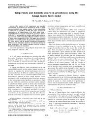
Figure 1 Weighted sigma-points <strong>for</strong> a 2 dimensional Gaussian<br />
random variable (RV). These sigma-points lie along the<br />
major eigen-axes of the RV’s covariance matrix and complete<br />
captures the first and second order statistics of the RV.<br />
The height of each sigma-point indicates its relative weight.<br />
where predictions are approximated as simply the function<br />
of the prior mean value <strong>for</strong> estimates (no expectation<br />
taken). The noise means are denoted by ¯v and ¯n, and are<br />
usually assumed to equal to zero. Furthermore, the covariances<br />
ˆ Plin xkyk and ˆ Plin are determined by linearizing the<br />
˜yk<br />
system model, Eqs. (1) and (2), around the current estimate<br />
of the state and then determining (approximating) the posterior<br />
covariance matrices analytically <strong>for</strong> the linear system<br />
(see [12] <strong>for</strong> exact equations). This is equivalent to<br />
applying the linear <strong>Kalman</strong> filter covariance update equations<br />
to the first-order linearization of the nonlinear system.<br />
As such, the EKF can be viewed as providing “first-order”<br />
approximations to the optimal terms in Eq. (3). As mentioned<br />
earlier, these approximations used in the EKF can<br />
result in large errors in the estimates and even divergence<br />
of the filter.<br />
THE SIGMA-POINT KALMAN FILTER<br />
The sigma-point <strong>Kalman</strong> filter address the approximation<br />
issues of the EKF. This is achieved through a fundamentally<br />
different approach <strong>for</strong> calculating the posterior 1st and<br />
2nd order statistics of a random variable that undergoes a<br />
nonlinear trans<strong>for</strong>mation. The state distribution is again<br />
represented by a GRV, but is now specified using a minimal<br />
set of deterministically chosen weighted sample points<br />
(See Fig. 1). These samples, called sigma-points, completely<br />
capture the true mean and covariance of the prior<br />
random variable, and when propagated through the true<br />
nonlinear system, captures the posterior mean and covariance<br />
accurately to the 2nd order (Taylor series expansion)<br />
<strong>for</strong> any nonlinearity (3rd order accuracy is achieved if the<br />
prior random variable has a symmetric distribution, such<br />
as the exponential family of pdfs.) The basic sigma-point<br />
approach (SPA) can be described as follows [9, 21]:<br />
The <strong>Sigma</strong>-point Approach (SPA)<br />
1. A set of weighted samples (sigma-points) are deterministically<br />
calculated using the mean and squareroot<br />
decomposition of the covariance matrix of the<br />
prior random variable. As a minimal requirement the<br />
sigma-point set must completely capture the first and<br />
second order moments of the prior random variable.<br />
Higher order moments can be captured, if so desired,<br />
at the cost of using more sigma-points.<br />
2. The sigma-points are propagated through the true<br />
nonlinear function using functional evaluations alone,<br />
i.e., no analytical derivatives are used, in order to generate<br />
a posterior sigma-point set.<br />
3. The posterior statistics are calculated (approximated)<br />
using tractable functions of the the propagated sigmapoints<br />
and weights. Typically these take on the <strong>for</strong>m<br />
of simple weighted sample mean and covariance calculations<br />
of the posterior sigma-points.<br />
To be more specific: Consider propagating a random variable<br />
x ∈ R L through an arbitrary nonlinear function y =<br />
g(x). Assume x has mean ¯x and covariance Px. To calculate<br />
the statistics of y, we <strong>for</strong>m a set of 2L +1sigma-points<br />
{X i; i=0,...,2L} where X i ∈ R L . The sigma-points are calculated<br />
using the following general selection scheme:<br />
X 0 = ¯x<br />
X i = ¯x + ζ √ <br />
Px<br />
X i = ¯x − ζ √ <br />
Px<br />
i<br />
i<br />
i=1,...,L<br />
i=L+1,...,2L<br />
(12)<br />
where ζ is a scalar scaling factor that determines the spread<br />
√P<br />
of the sigma-points around ¯x and indicates the ith<br />
i<br />
column of the matrix square-root of the covariance matrix<br />
P. Once the sigma-points are calculated from the prior<br />
statistics as shown above, they are propagated through the<br />
nonlinear function,<br />
Yi = g (X i) i=0,...,2L (13)<br />
and the mean and covariance of y are approximated using<br />
a weighted sample mean and covariance of the posterior<br />
sigma-points,<br />
¯y ≈<br />
Py ≈<br />
Pxy ≈<br />
2L<br />
w<br />
i=0<br />
m i Yi<br />
2L<br />
2L<br />
w c ijYiY T j<br />
i=0 j=0<br />
2L<br />
2L<br />
i=0 j=0<br />
(14)<br />
(15)<br />
w c ijX iY T j , (16)<br />
where w m i and w c ij are scalar weights. Note, all weights<br />
need not be positive valued. In fact, depending on the specific<br />
sigma-point approach at hand, certain weights on the<br />
cross-terms are set equal to zero, i.e., wij =0<strong>for</strong> certain<br />
{i, j; i = j}. The specific values of the weights (w) and the<br />
scaling factors (ζ) depend on the type of sigma-point approach<br />
used: These include the unscented trans<strong>for</strong>mation
Actual (sampling) Linearized (EKF)<br />
Ý Ü <br />
mean<br />
true mean<br />
covariance<br />
true covariance<br />
Ý Ü<br />
ÈÝ ÖÈÜ Ö Ì<br />
ÖÈÜ Ö Ì<br />
Ü<br />
sigma points<br />
SP mean<br />
<br />
weighted sample mean<br />
and covariance<br />
SP covariance<br />
<strong>Sigma</strong>−<strong>Point</strong><br />
Figure 2 2D example of sigma-point approach.<br />
trans<strong>for</strong>med<br />
sigma points<br />
[9] and the Stirling-interpolation based central difference<br />
trans<strong>for</strong>mation [14] to name but two.<br />
Note that the sigma-point approach differs substantially<br />
from general stochastic sampling techniques such as<br />
Monte-Carlo integration which require orders of magnitude<br />
more sample points in an attempt to propagate an accurate<br />
(possibly non-Gaussian) distribution of the state. The<br />
deceptively simple sigma-point approach results in posterior<br />
approximations that are accurate to the third order <strong>for</strong><br />
Gaussian inputs <strong>for</strong> all nonlinearities. For non-Gaussian<br />
inputs, approximations are accurate to at least the secondorder,<br />
with the accuracy of third and higher order moments<br />
determined by the specific choice of weights and scaling<br />
factors [21]. Furthermore, no analytical Jacobians of the<br />
system equations need to be calculated as is the case <strong>for</strong><br />
the EKF. This makes the sigma-point approach very attractive<br />
<strong>for</strong> use in “black box” systems where analytical expressions<br />
of the system dynamics are either not available or not<br />
in a <strong>for</strong>m which allows <strong>for</strong> easy linearization.<br />
A simple comparative example of the sigma-point approach<br />
is shown in Figure 2 <strong>for</strong> a 2-dimensional system:<br />
the left plot shows the true mean and covariance propagation<br />
using Monte Carlo sampling; the center plots show<br />
the results using a linearization approach as would be done<br />
in the EKF; the right hand plots show the per<strong>for</strong>mance of<br />
the sigma-point approach (note, only 5 sigma-points are<br />
needed <strong>for</strong> the 2D case). The superior per<strong>for</strong>mance of the<br />
sigma-point approach is clearly evident.<br />
Implementing the SPKF Algorithm<br />
The sigma-point <strong>Kalman</strong> filter is a straight<strong>for</strong>ward extension<br />
of the sigma-point approach to the recursive estimation<br />
in Eqs. (3)-(8), where the state RV is redefined<br />
as the concatenation of the original state and noise variables:<br />
xa k = [ xT k vT k nT k ]T . The sigma-point selection<br />
scheme (Equation 12) is applied to this new aug-<br />
mented state RV to calculate the corresponding sigma-point<br />
set, X a a<br />
k,i; i=0,...,2L where X k,i ∈ RLx+Lv+Ln . The<br />
pseudo-code <strong>for</strong> the SPKF is given below:<br />
• Initialization:<br />
ˆx0 = E[x0] , Px0 = E[(x0 − ˆx0)(x0 − ˆx0) T ˆx<br />
]<br />
a 0 = E [x a 0]= ˆx T 0 ¯v T 0 ¯n T P<br />
T 0<br />
a 0 =<br />
<br />
E (x a 0 − ˆx a 0)(x a 0 − ˆx a =<br />
<br />
T<br />
0)<br />
⎡<br />
⎤<br />
Px0 0 0<br />
⎣ 0 Rv0 ⎦<br />
0 0 Rn<br />
• For k =1,...,∞ :<br />
1. Set t = k − 1<br />
2. Calculate sigma-points:<br />
X a t = ˆx a t ˆx a t + ζ P a t ˆx a t − ζ P a t<br />
3. Time-update equations:<br />
X x<br />
k|t = f (X x t , X v t , ut)<br />
ˆx −<br />
k<br />
P − x k<br />
=<br />
=<br />
2L<br />
w<br />
i=0<br />
m i X x<br />
i,k|t<br />
2L<br />
2L<br />
w<br />
i=0 j=0<br />
c x x T ij X i,k|t X j,k|t<br />
4. Measurement-update equations:<br />
Y k|t = h X x <br />
k|t, X n ˆy<br />
t<br />
−<br />
k =<br />
2L<br />
w<br />
i=0<br />
m i Y i,k|t<br />
P˜y k =<br />
2L<br />
2L<br />
w<br />
i=0 j=0<br />
c T ij Y i,k|t Y i,k|t<br />
Pxkyk =<br />
2L<br />
2L<br />
w<br />
i=0 j=0<br />
c x T ij X i,k|t Y i,k|t<br />
Kk = Pxkyk P −1<br />
ˆxk =<br />
˜y k<br />
ˆx − <br />
k + Kk yk − ˆy −<br />
k<br />
Pxk = P − x − KkP˜y k kK T k<br />
• Parameters: x a = x T<br />
v T n T T , X a =<br />
x T<br />
(X ) (X v ) T<br />
(X n ) T T , ζ is scaling parameter<br />
that determines the spread of the sigma-points around the<br />
prior mean, L is the dimension of the augmented state, Rv<br />
is the process-noise covariance, Rn is the observation-noise<br />
covariance, and w m i and w c ij are the scalar weights.<br />
The specific type of resulting SPKF is determined by the<br />
choice of sigma-point selection scheme (weights & scaling<br />
factors) as well as the specific method by which the<br />
propagated sigma-points are combined in order to calculate<br />
the posterior covariance matrices. In Appendix A we
summarize two specific SPKF approaches, the square-root<br />
unscented <strong>Kalman</strong> filter (SRUKF) [23] and the squareroot<br />
central difference <strong>Kalman</strong> filter (SRCDKF) [14]. The<br />
square-root implementations propagate (and update) directly<br />
the square-root of the state covariance matrix, thus<br />
avoiding the need to per<strong>for</strong>m a direct matrix square-root<br />
operation at each time step. This provides increased computational<br />
efficiency as well as robust numerical stability.<br />
Other variations include efficient implementations when<br />
the noise is assumed additive (allowing fewer sigma-points<br />
to be used), or <strong>for</strong> special state-transition structures (as with<br />
pure parameter estimation) [7, 21]. Note that the overall<br />
computational complexity of the SPKF is the same as that<br />
of the EKF.<br />
SPKF BASED GPS/INS INTEGRATION<br />
We now describe the application of the SPKF to the problem<br />
of loosely coupled GPS/INS integration <strong>for</strong> guidance,<br />
navigation and control (GNC) of an unmanned aerial vehicle<br />
(UAV). Our UAV research plat<strong>for</strong>m (software simulator,<br />
hardware-in-the-loop simulator & flight vehicle) is<br />
based on a fully instrumented XCell-90 R/C helicopter (see<br />
Figure 3), originally designed by MIT’s Laboratory <strong>for</strong> In<strong>for</strong>mation<br />
and Decision Systems [3]. The avionics package<br />
includes an Inertial Sciences ISIS MEMS based IMU,<br />
an Ashtech G12 10Hz GPS, a barometric altimeter and<br />
a DSP Design TP400 PC104 based flight computer running<br />
QNX-4. Our nonlinear control system (which requires<br />
state-estimates) is based on an efficient state-dependent<br />
Ricatti-equation (SDRE) framework that has proven to be<br />
significantly superior and more robust than standard LQR<br />
methods[2, 1].<br />
The existing GPS/INS navigation filter was based on an<br />
MIT designed high-per<strong>for</strong>mance hand-tuned EKF implementation<br />
[4]. Our proposed estimator simply replaced<br />
the EKF in MIT’s system with a SPKF based estimator<br />
(SRCDKF). All our experimental results in later sections<br />
will use the original EKF based navigation filter as a baseline<br />
reference. As a further extension, we also implemented<br />
a SPKF based sensor latency compensation technique.<br />
We compared our SPKF based system per<strong>for</strong>mance<br />
to the baseline system with specific focus on: 1) Improved<br />
six-degrees-of-freedom (6DOF) state estimation accuracy,<br />
2) SPKF based compensation <strong>for</strong> GPS latency, 3) Evaluation<br />
of improved closed-loop control envelope.<br />
We will next discuss the UAV specific system process and<br />
observation (measurement) models used inside our SPKF<br />
based system.<br />
Process Model<br />
Even though we used a high-fidelity (70 parameters, 43<br />
states) nonlinear dynamic model of UAV movement [2] <strong>for</strong><br />
Figure 3 Instrumented X-Cell-90 helicopter in flight.<br />
our UAV simulators and control system design, due to its<br />
high computational complexity it is not ideally suited <strong>for</strong><br />
use within the navigation filter loop. For this reason we<br />
opted <strong>for</strong> the standard IMU driven kinematic process model<br />
<strong>for</strong>mulation that comprises an INS mechanization component<br />
[16, 17] and a IMU sensor error model component.<br />
Because low cost MEMS based IMUs such as the one used<br />
in our avionics system have large bias and scale factor errors<br />
we included these components into our state vector to<br />
be estimated. The estimated values of these error components<br />
are then used to correct the raw IMU acceleration and<br />
gyro-rate measurements be<strong>for</strong>e they are used inside the INS<br />
mechanization equations of the process model. The 16 dimensional<br />
state vector of our system is given by,<br />
x = p T v T e T a T b ωT b<br />
<br />
(17)<br />
where p =[ x y z ] T and v =[ vx vy vz ] T are<br />
the position and velocity vectors of the vehicle in the navigation<br />
frame, e =[ e0 e1 e2 e3 ] T is the unity norm<br />
vehicle attitude quaternion, ab = [ axb ayb azb ] T<br />
is the vector of IMU acceleration biases, and ωb =<br />
[ pb qb rb ] T is the IMU gyro rate bias vector. Note<br />
that we could have include a separate scale factor in addition<br />
to the bias term in the state vector. However, in our<br />
experiments, we found it sufficient to model the combined<br />
effect of the bias and scale error terms as a single timevarying<br />
bias term.<br />
The continuous time kinematic navigation equations (INS<br />
mechanization equations and error model) operating on this<br />
state vector and driven by the error corrected IMU measure-
ments are given below:<br />
˙p<br />
˙v<br />
=<br />
=<br />
v<br />
C<br />
(18)<br />
n b (ā − a˜rimu )+ 0 0 1 T g (19)<br />
˙e = − 1<br />
2 ˜ Ω¯ωe (20)<br />
˙ab = wabk (21)<br />
(22)<br />
˙ωb = wωb k<br />
Cn b is the direction cosine matrix (DCM) trans<strong>for</strong>ming vectors<br />
from the body frame to the navigation frame. The<br />
DCM is a nonlinear function of the current attitude quaternion<br />
and is given by<br />
C n <br />
b = C b T n<br />
⎡<br />
0.5 − e<br />
=2⎣<br />
2 2 − e 2 3 e1e2 − e0e3 e1e3 + e0e2<br />
e1e2 + e0e3 0.5 − e 2 1 − e 2 3 e2e3 − e0e1<br />
⎤<br />
⎦ .<br />
e1e3 − e0e2 e2e3 + e0e1 0.5 − e 2 1 − e 2 2<br />
(23)<br />
The term g is the gravitational acceleration component and<br />
ā and ¯ω are the bias and noise corrected IMU accelerometer<br />
and gyro rate measurements, i.e.,<br />
ā = ã − ab − na (24)<br />
¯ω = ˜ω − ωb − C b nωc − nω . (25)<br />
In the above equations ã and ˜ω are the raw measurements<br />
coming from the IMU, na and nω are the IMU acceleration<br />
and gyro-rate measurement noise terms, and ωc is the rotational<br />
rate of the earth as measured in the navigation frame<br />
(Coriolis effect). In general, ωc is a function of the location<br />
of the navigational frame relative to the earth frame and<br />
hence is time-varying as the navigation frame moves relative<br />
to the earth frame. However, <strong>for</strong> our purposes (aggressive<br />
autonomous UAV flight within a very small airspace<br />
volume) we assumed the navigation frame does not change<br />
relative to the earth frame resulting in a constant ωc <strong>for</strong><br />
a given origin location (lat/long) of our navigation frame.<br />
˜Ω¯ω is a 4×4 skew-symmetric matrix [19] composed of the<br />
error corrected IMU gyro-rate measurements, i.e.,<br />
⎡<br />
⎤<br />
˜Ω¯ω =<br />
⎢<br />
⎣<br />
0 ¯ωp ¯ωq ¯ωr<br />
−¯ωp 0 −¯ωr ¯ωq<br />
−¯ωq ¯ωr 0 −¯ωp<br />
−¯ωr −¯ωq ¯ωp 0<br />
⎥<br />
⎦<br />
. (26)<br />
In Eq. (19), a˜rimu is the IMU-lever-arm coupling component<br />
due to the IMU not being located at the center of<br />
gravity of the vehicle. This component can be ignored if<br />
the navigation filter computes the state estimate at the IMU<br />
location. This IMU centric navigation solution can then<br />
simply be trans<strong>for</strong>med to the center of gravity location after<br />
the fact as needed by the vehicle control system.<br />
The final components of the process model, Eqs. (21) and<br />
(22) models the time-varying nature of the IMU sensor bias<br />
error terms. Usually, sensor error in an INS are modelled<br />
as a zero-mean, stationary, first-order Gauss-Markov process<br />
[13]. Since the biases and scale factors of low cost<br />
MEMS based IMU sensors exhibit non-zero mean and nonstationary<br />
behaviour, the errors are modelled as a random<br />
walk, in order to improve the tracking of these time-varying<br />
errors by the navigation filter. This does however require<br />
that the effect of these errors be observable through the<br />
specific choice of measurement model.<br />
The position and velocity discrete-time updates are calculated<br />
by the following simple first-order Euler update<br />
pk+1 = pk + ˙pk · dt (27)<br />
vk+1 = vk + ˙vk · dt , (28)<br />
where ˙pk and ˙vk are calculated using Eqs. (18) and (19)<br />
and dt is the integration time-step of the system (in our system<br />
this was dictated by the IMU rate, i.e., dt =10ms).<br />
The quaternion propagation equation can be discretized<br />
with an analytical calculation of the exponent of the skewsymmetric<br />
matrix given by Stevens [19]. The discrete-time<br />
update can be written as<br />
If we further denote<br />
ek+1 = exp<br />
<br />
− 1<br />
2 ˜ <br />
Ω · dt ek . (29)<br />
∆φ = ¯ωp · dt (30)<br />
∆θ = ¯ωq · dt (31)<br />
∆ψ = ¯ωr · dt , (32)<br />
as effective rotations around the (body frame) roll, pitch<br />
and yaw axes undergone by the vehicle during the time period<br />
dt, assuming that the angular rates ¯ωp, ¯ωq and ¯ωr remained<br />
constant during that interval, we can introduce the<br />
4 × 4 skew-symmetric matrix<br />
Φ∆ = ˜ =<br />
Ω · dt<br />
⎡<br />
0<br />
⎢ −∆φ<br />
⎣ −∆θ<br />
∆φ<br />
0<br />
∆ψ<br />
∆θ<br />
−∆ψ<br />
0<br />
⎤<br />
∆ψ<br />
∆θ ⎥<br />
−∆φ ⎦<br />
−∆ψ −∆θ ∆φ 0<br />
. (33)<br />
Using the definition of the matrix exponent and the skew<br />
symmetric property of Φ∆, we can write down the following<br />
closed-<strong>for</strong>m solution:<br />
<br />
exp − 1<br />
2 Φ∆<br />
<br />
= I cos(s) − 1<br />
2 Φ∆<br />
sin(s)<br />
,<br />
s<br />
where<br />
(34)<br />
s = 1 <br />
<br />
2<br />
∆φ ∆θ ∆ψ =<br />
<br />
1<br />
(∆φ) 2 +(∆θ) 2 +(∆ψ) 2 .<br />
2<br />
(35)<br />
See [21] <strong>for</strong> a proof of this closed-<strong>for</strong>m solution. Eqs.<br />
(29) and (34) ensure (at least theoretically) that the updated
quaternion ek+1 has a unit norm. However, a small Lagrange<br />
multiplier term can be added to the first component<br />
of Equation 34 to further maintain numerical stability and<br />
the unity norm of the resulting quaternion. The resulting<br />
final solution <strong>for</strong> the time-update of the quaternion vector<br />
is given by<br />
<br />
ek+1 = I (cos(s)+η · dt · λ) − 1<br />
2 Φ∆<br />
<br />
sin(s)<br />
ek .<br />
s<br />
(36)<br />
where λ =1−ek 2 is the deviation of the square of the<br />
quaternion norm from unity due to numerical integration<br />
errors, and η is the factor that determines the convergence<br />
speed of the numerical error. These factors serve the role of<br />
the above mentioned Lagrange multiplier that ensures that<br />
the norm of the quaternion remains close to unity [15]. The<br />
constraint on the speed of convergence <strong>for</strong> stability of the<br />
numerical solution is η · dt < 1 [4].<br />
Finally, the discrete time random-walk process <strong>for</strong> the IMU<br />
sensor error terms are given by<br />
(37)<br />
abk+1 = abk + dt · wabk ωbk+1 = ωbk + dt · wωb ,<br />
k<br />
(38)<br />
where wab k and wωb k are zero-mean Gaussian random<br />
variables.<br />
Note that these navigation equations are considered a direct<br />
<strong>for</strong>mulation, as opposed to the alternative indirect (error)<br />
<strong>for</strong>mulation. This choice was made <strong>for</strong> consistency with<br />
the MIT EKF implementation. The trade-offs between direct<br />
versus indirect <strong>for</strong>mulations with the SPKF are currently<br />
being investigated.<br />
Observation Models<br />
Our system made use of 2 independent avionic sensors to<br />
aid the INS: a 10Hz, 50ms latency GPS (Ashtech G12) and<br />
a barometric altimeter that measures absolute altitude as a<br />
function of ambient air pressure. The observation models<br />
used in our system <strong>for</strong> these sensors (see below) are highly<br />
nonlinear, making the use of the SPKF framework again<br />
preferable to an EKF solution.<br />
GPS: Since our GPS antenna is not located at the same<br />
location in the body frame as the IMU, it not only observes<br />
the bodies position and velocity in the navigation frame,<br />
but also the body’s attitude relative to the navigation frame<br />
due to the “lever-arm effect”. More specifically, the GPS<br />
observation model is given by:<br />
GP S<br />
p<br />
GP S<br />
vk = vk−N + C n b ωk−N × ˜rgps + nvk<br />
k = pk−N + C n b ˜rgps + npk (39)<br />
, (40)<br />
where pk−N and vk−N are the time-delayed (by N samples<br />
due to sensor latency) 3D navigation-frame position<br />
and velocity vectors of the vehicle, ˜rgps is the location of<br />
the GPS antenna in the body frame (relative to the IMU location),<br />
ωk−N are the true rotational rates of the vehicle at<br />
time k − N, and npk and nvk are stochastic measurement<br />
noise terms. Here the noise terms are modeled as being<br />
time-dependent. This is due to the fact that the accuracy of<br />
observations vary over time according to the current PDOP<br />
value of the loosely coupled GPS solution. Since the DCM,<br />
Cn b , in Eqs. (39) and (40) are a function of the attitude<br />
quaternion, the GPS measurements provides in<strong>for</strong>mation<br />
not only of the vehicles position and velocity, but also of<br />
its attitude. This removes the need <strong>for</strong> an absolute attitude<br />
sensor such as a magnetic compass or tilt-sensor. However,<br />
this will also result in the non-observability of the IMU sensor<br />
errors during prolonged periods of GPS outages, which<br />
in turn can lead to significant INS drift.<br />
The time delay (N samples) in the GPS model equations is<br />
due to the internal GPS processing latency inherent to all<br />
loosely coupled GPS solutions. This implies that the latest<br />
GPS measurement relates to the state of the vehicle as it<br />
was a number of samples in the past. If the specific latency<br />
of the GPS is small, it can (and often is) ignored. However,<br />
if the latency is significant, care must be taken when fusing<br />
this lagged in<strong>for</strong>mation with the current estimate of the vehicle’s<br />
state in the measurement update step of the <strong>Kalman</strong><br />
filter.<br />
Barometric altimeter: Ambient air pressure provides an<br />
accurate source of sea-level altitude in<strong>for</strong>mation. Important<br />
sources of error are sensor quantization and measurement<br />
noise. We used a high-end altimeter with 10−3psi (0.6 meters)<br />
resolution. The measurement noise was assumed to<br />
be zero-mean, white and Gaussian. The observation model<br />
that incorporates these effects are:<br />
z alt<br />
k = − 1<br />
ϕ ln<br />
q<br />
ρ0 ⌊(ρ0 exp (ϕ · zk)+nza ) /ρq0<br />
⌋<br />
<br />
(41)<br />
ρ0<br />
where ρ0 is the nominal air pressure at sea-level, ϕ is<br />
the pressure decay rate with altitude constant (1.16603 ×<br />
10−4psi/m), zk is the current navigation-frame z-axis position<br />
of the vehicle, ρ q<br />
0 is the air pressure quantization resolution<br />
of the altimeter (10−3psi), zalt k is the altimeter output<br />
and ⌊·⌋ is the integer flooring function. This model is<br />
not only a nonlinear function of the state, but the measurement<br />
noise also effects the output altitude measurement in<br />
a non-additive fashion. Again, <strong>for</strong> such a model the use of<br />
the SPKF not only allows <strong>for</strong> a much simpler implementation<br />
than the EKF (no analytical derivatives need to be<br />
calculated), but will also results in more accurate estimation<br />
results.<br />
SPKF Based Sensor Latency Compensation<br />
As mentioned in the previous section, when fusing latency<br />
delayed measurements with the current best prediction of<br />
the vehicle’s state, care must be taken to incorporate this<br />
in<strong>for</strong>mation in a mathematically correct fashion. Previous
approaches to deal with this problem either store all of the<br />
state estimates and observations during the latency period<br />
and then re-run the complete filter when the latency lagged<br />
observation finally arrives, or apply accumulated correction<br />
terms to the state estimate based on a time-convolved<br />
linearized approximation of the system [11]. The first approach,<br />
although accurate incurs an exceedingly high computational<br />
penalty, precluding its use in real-time systems.<br />
The second approach on the other hand can be highly inaccurate<br />
if the system process and measurement equations<br />
are significantly nonlinear.<br />
For our SPKF based navigation filter, we derived a new<br />
approach to deal with the latency issue based on accurately<br />
maintaining the relevant cross-covariance matrices<br />
across time. These terms are needed to <strong>for</strong>mulate a modified<br />
<strong>Kalman</strong> gain matrix, which is used to fuse the current<br />
prediction of the state with an observation related to a prior<br />
(lagged) state of the system. The system process model is<br />
first augmented such that a copy of the prior system state<br />
is maintained across time. The observation model is also<br />
adapted to relate the current GPS observation to this lagged<br />
(but-maintained) state. The correct gain terms are then automatically<br />
calculated inside the SPKF filter. The SPKF<br />
allows <strong>for</strong> such a simple solution due to the fact that it does<br />
not need to linearize the system equations when calculating<br />
the relevant posterior statistics. For a more detailed exposition<br />
of this method, see Appendix B and [21, 24].<br />
EXPERIMENTAL RESULTS<br />
This section presents a number of experimental results<br />
comparing our proposed SPKF based GPS/INS system<br />
with an similar system built around an EKF implementation.<br />
The first set of experiments were all per<strong>for</strong>med in simulation<br />
using the high-fidelity MIT-Draper-XCell-90 model<br />
based UAV simulator plat<strong>for</strong>m [4]. All relevant avionic<br />
sensors (IMU, GPS, altimeter, etc.) as well as all actuators<br />
were accurately modeled, including effects such as GPS latency<br />
and IMU sensor bias errors and drift. The purpose<br />
of the simulation based experiments were both to compare<br />
the per<strong>for</strong>mance of our new proposed SPKF approaches to<br />
that of the existing EKF approach in a controlled (repeatable)<br />
environment where the ground truth state in<strong>for</strong>mation<br />
is available. This allows <strong>for</strong> objective comparison of estimation<br />
accuracy.<br />
The second set of experiments were per<strong>for</strong>med on real<br />
flight data using telemetry recordings of actual autonomous<br />
flights per<strong>for</strong>med by the UAV. Although ground truth in<strong>for</strong>mation<br />
is not available <strong>for</strong> these experiments to judge<br />
absolute accurate, it still allows <strong>for</strong> direct qualitative comparison<br />
between the EKF and SPKF based systems. Specific<br />
per<strong>for</strong>mance issues related to real world events such<br />
as GPS outages were investigated.<br />
Figure 4 Simulated UAV trajectory used <strong>for</strong> state estimation<br />
experiments.<br />
Simulation experiments<br />
The first simulated experiment per<strong>for</strong>med was used to provide<br />
quantitative comparisons between the EKF, SPKF, and<br />
latency compensated SPKF. The helicopter was flown (in<br />
simulation) along a complex trajectory that increased in<br />
“aggressiveness” over time. Figure 4 shows a 3D representation<br />
of this flight-plan trajectory with the helicopter’s<br />
true attitude superimposed at certain intervals. The simulated<br />
flight included complex acrobatic maneuvers such<br />
as rapid-rise-and-hover, figure-eights, split-s, etc. For this<br />
experiment we did not “close the loop” <strong>for</strong> the flight control<br />
system. In other words, the control system used the<br />
true known states of vehicle <strong>for</strong> the online calculation of<br />
the control law. The SPKF or EKF estimated state was<br />
not fed back to the control system. This was done to ensure<br />
that the helicopter flew exactly the same flight profile<br />
when comparing the per<strong>for</strong>mance of the different estimators.<br />
Again, the repeatability and access to the ground truth<br />
is what makes the high-fidelity simulation environment so<br />
attractive <strong>for</strong> these initial investigations.<br />
Table 1 compares the average root-mean-square (RMS) estimation<br />
errors <strong>for</strong> the three different state estimators. We<br />
also show (in brackets) the relative error reduction percentage<br />
<strong>for</strong> each of the two SPKF estimators compared to the<br />
EKF. The normal SPKF is able to reduce the 3D position<br />
and velocity estimation errors by about 10% and the roll<br />
and pitch angle estimation errors by about 20%.<br />
The biggest improvement over the EKF, 55%, is in the estimation<br />
of the yaw (heading) angle. The GPS latency compensated<br />
SPKF goes even further with a 33% reduction in<br />
position, velocity, roll angle and pitch angle errors. The<br />
yaw angle error reduction is again the highest at 65%. We<br />
repeated this experiment numerous times with different initializations<br />
and realizations of measurement noise as well<br />
as flying different flight trajectories and all of the results<br />
consistently confirmed the same relative per<strong>for</strong>mance between<br />
the different estimators as presented in this experiment.<br />
Clearly, even though the normal SPKF already out-
Table 1 UAV state estimation results : EKF vs. SPKF (with and without GPS latency compensation). The table reports average<br />
(over complete flight trajectory) root-mean-square (RMS) estimation errors <strong>for</strong> the EKF, SPKF (without GPS latency compensation)<br />
and SPKF (with GPS latency compensation) <strong>for</strong> the simulated flight shown in Figure 4. The estimation error reduction<br />
percentages are shown <strong>for</strong> all filters (relative to EKF).<br />
m/s<br />
degrees<br />
m<br />
degrees<br />
degrees<br />
5<br />
4<br />
3<br />
2<br />
1<br />
1<br />
0.5<br />
Algorithm Average RMS Error<br />
position velocity Euler angles (degrees)<br />
(m) (m/s) roll pitch yaw<br />
EKF 2.1 0.57 0.25 0.32 2.29<br />
SPKF (without latency compensation) 1.9 (10%) 0.52 (9%) 0.20 (20%) 0.26 (19%) 1.03 (55%)<br />
SPKF (with latency compensation) 1.4 (32%) 0.38 (34%) 0.17 (32%) 0.21 (34%) 0.80 (65%)<br />
SPKF<br />
EKF<br />
3D Position 3D position errorError<br />
0<br />
0 50 100 150 200<br />
3D 3D Velocity velocity error Error<br />
2<br />
1.5<br />
SPKF<br />
EKF<br />
0<br />
0 50 100 150 200<br />
time (s)<br />
3<br />
2<br />
1<br />
Absolute Pitch Angle Error<br />
0<br />
0 50 100<br />
Absolute Roll Angle Error<br />
150 200<br />
2<br />
1.5<br />
SPKF<br />
EKF<br />
1<br />
0.5<br />
0<br />
0 50 100 150 200<br />
Absolute Yaw Angle Errors<br />
6<br />
SPKF<br />
EKF<br />
4<br />
2<br />
0<br />
0 50 100 150 200<br />
time<br />
SPKF<br />
EKF<br />
Figure 5 State estimation results - SPKF vs EKF (RMS error):<br />
[top] 3D position (32% error reduction). [2nd from top]<br />
3D velocity (34% error reduction). [middle] pitch (34% error<br />
reduction). [2nd from bottom] roll (32% error reduction).<br />
[bottom] yaw (65% error reduction).<br />
per<strong>for</strong>ms the EKF (as expected), correctly accounting <strong>for</strong><br />
GPS latency is well worth the extra ef<strong>for</strong>t.<br />
In order to clearly illustrate the difference in estimation per<strong>for</strong>mance<br />
between the EKF and the (latency compensated)<br />
SPKF we present the results of another run of the same<br />
simulation experiment, this time only showing the EKF and<br />
latency-compensated SPKF implementation plots. The position<br />
and velocity estimation errors are shown in the top<br />
two plots of Figure 5 and the Euler angle estimation errors<br />
are shown in the bottom three plots. As be<strong>for</strong>e the SPKF<br />
clearly outper<strong>for</strong>ms the EKF with the largest improvement<br />
again evident in the yaw (heading) angle estimation error.<br />
Figure 5 indicates how the EKF has a very large error in<br />
the yaw estimate <strong>for</strong> the first 80 seconds of the flight. This<br />
is due to a significant initial error in the underlying IMU<br />
bias error estimates. Even though the EKF and SPKF filters<br />
were initialized with exactly the same initial state estimates,<br />
the SPKF was able to converge to the true biases in<br />
the IMU measurements much quicker and then track them<br />
more accurately. This result has been corroborated independently<br />
in [18] (experiments focused on in-flight IMU<br />
alignment). This contributes (among other things) to more<br />
accurate Euler angle estimates. Although the average yaw<br />
estimate error improvement <strong>for</strong> the SPKF over the whole<br />
trajectory is 65%, this value does not accurately reflect the<br />
expected steady-state (after bias convergence) per<strong>for</strong>mance<br />
of the SPKF. Discounting this period, the average error improvement<br />
after bias convergence (t >80s) is 43%. The<br />
steady-state error improvement of the SPKF over the EKF<br />
is thus 32%, 34% and 43% respectively <strong>for</strong> the roll, pitch<br />
and yaw angle estimates.<br />
Another interesting per<strong>for</strong>mance characteristic to note from<br />
the Euler angle estimates in Figure 5 are the frequent high<br />
peaks in the EKF’s estimation error plots. These coincide<br />
with the onsets of aggressive maneuvers (banking, turns,<br />
rapid climbs, etc.) that pushes the vehicle into regimes of<br />
increased nonlinear response. The linearization errors of<br />
the EKF will there<strong>for</strong>e be more severe at these times resulting<br />
in poor estimation per<strong>for</strong>mance and increase estimation<br />
error. In contrast the SPKF is able to deal with these increased<br />
nonlinearities quite satisfactorily.
In the second set of simulated experiments we “closed the<br />
loop” in the GNC system by feeding the estimated states<br />
back to the SDRE control system. In other words, the vehicle<br />
control commands will now be a function of the estimates<br />
generated by either the EKF or SPKF estimator and<br />
not of the “true” vehicle states. This mimics (in simulation)<br />
the true interdependency between the estimation and<br />
control system as would occur in the real flight hardware<br />
during a fully autonomous flight. The helicopter is commanded<br />
to per<strong>for</strong>m an aggressive high speed nose-in turn.<br />
This maneuver requires the helicopter to fly along an imaginary<br />
circular trajectory while constantly pointing its nose<br />
towards the exact center of the circle. Accurate position,<br />
velocity and especially yaw angle estimates are needed to<br />
follow the desired flight plan with the desired attitude. Figure<br />
6 shows the results of this experiment <strong>for</strong> both the EKF<br />
and SPKF. The desired flight trajectory is indicated by the<br />
red curve, the true realized trajectory in blue and the estimated<br />
trajectory in green. The true attitude of the helicopter<br />
is indicated by periodic renderings of the vehicle<br />
itself along the flight path. Clearly <strong>for</strong> the SPKF case the<br />
estimated trajectory is not only close to the true trajectory<br />
(small estimation error), but the true trajectory is close to<br />
the desired trajectory which indicated good control per<strong>for</strong>mance.<br />
The EKF plots clearly shows worse per<strong>for</strong>mance<br />
according to both these criteria. Also evident from the plots<br />
is the much improved yaw angle tracking per<strong>for</strong>mance of<br />
the SPKF system compared to the EKF system. The helicopter<br />
renderings <strong>for</strong> the EKF indicate that the nose is not<br />
consistently pointing at the true center of the desired circle.<br />
The SPKF system, on the other hand, does much better<br />
in estimating and realizing the correct yaw attitude <strong>for</strong> this<br />
maneuver. EKF.<br />
Real flight data experiments<br />
Figure 7 shows the estimation results of the SPKF compared<br />
to the EKF based system on real flight telemetry. The<br />
UAV was flown under pilot guidance to a specified altitude<br />
at which point the system was switched over to fully autonomous<br />
flight. The autonomous flight plan was as follows:<br />
First the UAV held steady in hover <strong>for</strong> a number of<br />
seconds, after which it flew a square trajectory at a constant<br />
altitude of about 55-60 meters. Since no ground truth signal<br />
is available <strong>for</strong> absolute error comparison, we need to<br />
evaluate the results on more subjective terms. For this purpose,<br />
a top-down (2D) projection of the estimation results<br />
is quite insightful (see Figure 8).<br />
Notice the significant number of GPS outages that occurred<br />
during the pilot guided ascent to the hovering altitude (sshaped<br />
curve). Clearly the SPKF appears to more accurately<br />
track the (assumed) true underlying trajectory during<br />
this outage period. The EKF generated position estimate<br />
exhibits an erratic jump just be<strong>for</strong>e the GPS measurements<br />
becomes available again (see Figure 8 at coordinates<br />
z (m) : Altitude<br />
EKF<br />
SPKF<br />
Figure 6 Closed-loop control per<strong>for</strong>mance comparison.<br />
50<br />
40<br />
30<br />
20<br />
10<br />
0<br />
GPS<br />
ekf<br />
spkf<br />
100<br />
80<br />
60<br />
x (m) : North<br />
3D Position<br />
40<br />
20<br />
0<br />
-60<br />
-40<br />
-20<br />
0<br />
20<br />
y (m) : East<br />
Figure 7 Estimated 3D position of test flight. The UAV<br />
lifted off and flew a complex sweeping S-maneuver until it<br />
reached its hover altitude at about 50m. At this point it hovered<br />
<strong>for</strong> a number of seconds after which it attempted to fly<br />
a horizontal square-profile. After the square was completed<br />
it hovered again <strong>for</strong> a number of seconds and then landed.<br />
40
x (m) : North<br />
100<br />
80<br />
60<br />
40<br />
20<br />
0<br />
GPS<br />
ekf<br />
spkf<br />
-60 -40 -20 0 20 40<br />
y (m) : East<br />
Figure 8 Estimated 2D position of test flight (top view)<br />
{40, −60}). Figure 9 shows the effect of this on the separate<br />
north, east and down components of the estimated 3D<br />
position. This error is due to the inherent nature of the<br />
INS solution (derived from integrating the bias compensated<br />
IMU gyro and accelerometer data) to drift during periods<br />
of GPS outage. Since the SPKF per<strong>for</strong>ms a more accurate<br />
time-update during these periods than the EKF, and<br />
possibly also more accurately tracks the underlying IMU<br />
biases, the resulting SPKF estimates appear more robust to<br />
GPS outages in general. We are still investigating these<br />
claims further.<br />
CONCLUSIONS<br />
In this paper we presented a method <strong>for</strong> integrated navigation<br />
based on the sigma-point <strong>Kalman</strong> filter. The SPKF<br />
provides superior per<strong>for</strong>mance over the current industry<br />
standard, EKF, by better accounting <strong>for</strong> nonlinearities and<br />
accommodating asynchronous and lagged sensor measurements.<br />
The computational complexity of the SPKF is<br />
equivalent to the EKF. While per<strong>for</strong>mance comparisons<br />
were based on a specific UAV rotor craft plat<strong>for</strong>m, the general<br />
implementation of the navigation filter and SPKF approach<br />
makes it applicable to general integrated navigation<br />
systems, with per<strong>for</strong>mance gains expected independent of<br />
the vehicle or specific sensors used.<br />
We continue to investigate trade-offs between direct and<br />
indirect navigation equations, alternative quaternion representations,<br />
ability to track scale and bias, as well as robustness<br />
to GPS outages. Additional extensions include a<br />
tightly-coupled integration approach and additional sensor<br />
augmentations. We are also investigating the utility of replacing<br />
the higher-end IMU in our INS system with a low-<br />
m<br />
m<br />
m<br />
80<br />
60<br />
40<br />
20<br />
40<br />
20<br />
0<br />
-20<br />
-40<br />
-60<br />
-80<br />
-25<br />
-30<br />
-35<br />
-40<br />
-45<br />
posN<br />
GPS<br />
ekf<br />
spkf<br />
260 265 270 275<br />
posE<br />
GPS<br />
ekf<br />
spkf<br />
260 265 270 275<br />
posD<br />
260 265<br />
s<br />
270<br />
GPS<br />
ekf<br />
spkf<br />
Figure 9 Estimated position (North, East and Down) during<br />
test flight (EKF vs. SPKF).<br />
cost IMU (
APPENDIX A : SPKF VARIANT PSEUDO-CODE<br />
This section provides the algorithmic pseudo-code <strong>for</strong> two<br />
different numerical robust and efficient square-root SPKF<br />
implementations [22, 23] . The first is based on the unscented<br />
trans<strong>for</strong>mation (a SPA scheme proposed by Julier<br />
& Uhlman[9]) and is called the square-root unscented<br />
<strong>Kalman</strong> filters (SR-UKF). The second SPKF is based on<br />
the central-difference trans<strong>for</strong>mation (a SPA scheme proposed<br />
separately by Norgaard et al. [14] and Ito et al.[8])<br />
and is called the square-root central difference <strong>Kalman</strong> filters<br />
(SR-CDKF).<br />
Square-Root UKF (SRUKF)<br />
• Initialization:<br />
ˆx0 = E [x0] , Sx0 = E[(x0 − ˆx0)(x0 − ˆx0) T ]<br />
ˆx a 0 = E [x a ]= ˆx0 ¯v ¯n T S a 0 = E [(xa 0 − ˆxa 0 )(xa0 − ˆxa 0 )T =<br />
]<br />
⎡<br />
⎤<br />
Sx0 0 0<br />
⎣ 0 Sv0 ⎦<br />
0 0 Sn<br />
• For k =1,...,∞ :<br />
1. Set t = k − 1<br />
2. Calculate sigma-points:<br />
X a t = ˆx a t ˆx a t + γS a xt ˆx a t − γS a xt<br />
3. Time-update equations:<br />
X x<br />
k|t = f (X a t , X v t , ut)<br />
2L<br />
ˆx −<br />
k = w<br />
i=0<br />
m i X x<br />
i,k|t<br />
S − xk =<br />
w c qr 1<br />
S − x k = cholupdate<br />
Y k|t = h X x<br />
ˆy −<br />
k<br />
=<br />
X x<br />
<br />
i,k|t, X n t<br />
2L<br />
w m i Y i,k|t<br />
i=0<br />
1:2L,k|t − ˆx −<br />
k<br />
<br />
S − x k , X x<br />
0,k|t − ˆx −<br />
k ,w (c)<br />
0<br />
4. Measurement-update equations:<br />
S˜y k =<br />
w <br />
c qr 1 Y 1:2L,k|t − ˆy −<br />
k<br />
<br />
<br />
S˜y k = cholupdate<br />
Px ky k<br />
=<br />
Kk =<br />
2L<br />
w c i<br />
i=0<br />
<br />
<br />
<br />
<br />
S˜y k , Y 0,k|t − ˆy −<br />
k ,w (c)<br />
0<br />
<br />
x<br />
X i,k|t − ˆx −<br />
k Y i,k|t − ˆy −T<br />
k<br />
Px ky k /S T ˜y k<br />
ˆxk = ˆx −<br />
k + Kk<br />
<br />
/S˜y k<br />
yk − ˆy −<br />
k<br />
U = KkS˜y k<br />
Sx k = cholupdate S − x k , U, −1 <br />
<br />
• Weights & parameters: γ = √ L + λ, w m 0 = λ/(L + λ),<br />
w c 0 = w m 0 +(1− α 2 + β), w c i = w m i =1/[2(L + λ)] <strong>for</strong><br />
i =1,...,2L. λ = α 2 (L + κ) − L is a compound scaling<br />
parameter, L is the dimension of the augmented state-vector,<br />
0
4. Calculate sigma-points <strong>for</strong> measurement update:<br />
ˆx an<br />
k|t = ˆx −<br />
k<br />
X an<br />
k|t<br />
=<br />
<br />
ˆx an<br />
k|t<br />
¯n <br />
, S an<br />
k|t =<br />
−<br />
Sxk ˆx an<br />
k|t + hSan k|t<br />
5. Measurement-update equations:<br />
Y k|t = h X x<br />
k|t, X n <br />
k|t<br />
ˆy −<br />
k<br />
=<br />
2L<br />
w m i Y i,k|t<br />
i=0<br />
S˜y k = qr<br />
<br />
w c1<br />
1<br />
0<br />
0 Sn<br />
ˆx an<br />
k|t − hSan k|t<br />
<br />
Y 1:L,k|t − Y L+1:2L,k|t<br />
<br />
w c2<br />
<br />
1 Y 1:L,k|t − Y L+1:2L,k|t − 2Y 0,k|t<br />
<br />
Px ky k<br />
=<br />
Kk =<br />
<br />
<br />
w c1<br />
1 S− x k<br />
Px ky k /S T ˜y k<br />
ˆxk = ˆx −<br />
k + Kk<br />
T Y 1:L,k|t − Y L+1:2L,k|t<br />
<br />
/S˜y k<br />
yk − ˆy −<br />
k<br />
U = KkS˜y k<br />
Sx k = cholupdate S − x k , U, −1 <br />
• Weights: w m 0 =(h 2 − L)/h 2 , w m i =1/(2h 2 ), w c1<br />
i =<br />
1/(4h 2 ) and w c2<br />
i =(h2− 1)/(4h 4 ) <strong>for</strong> i=1,...,2L where<br />
h ≥ 1 is the scalar central difference interval size which<br />
is optimally set equal to the square-root of the kurtosis of<br />
the prior random variable [14]. For Gaussian prior RVs, the<br />
optimal value is h = √ 3. The scaling factor h in the CDKF<br />
plays the same role of α in the UKF, i.e., it determines the<br />
spread of the sigma-points around the prior mean. L is the<br />
dimension of the augmented state vector.<br />
• Other parameters: Sv = √ Rv and Sn = √ Rn where Rv<br />
and Rn are the process-noise and observation-noise covariance<br />
matrices.<br />
• General note: Here we again augment the system state with<br />
the process noise and observation noise vectors (vk and nk)<br />
as we did <strong>for</strong> the UKF. For the CDKF, however, we split this<br />
augmentation between the time-update and measurementupdate,<br />
i.e., <strong>for</strong> the time-update the augmented state vector<br />
and augmented covariance matrix is given by<br />
x av<br />
k = x T k v T k<br />
and by<br />
x an<br />
k = x T k n T k<br />
T<br />
T<br />
, P av<br />
k =<br />
<br />
Pxk 0<br />
0 Rv<br />
, P an<br />
k =<br />
<br />
Pxk 0<br />
0 Rn<br />
<strong>for</strong> the measurement-update. Accordingly the sigma-point<br />
vectors are given by: X av = (X x ) T<br />
(X v ) T T and<br />
X an = (X x ) T<br />
(X n ) T T 2<br />
. Note: (·) is shorthand<br />
<strong>for</strong> the vector outer product, i.e., a 2 . = aa T .<br />
<br />
<br />
<br />
,<br />
,<br />
<br />
<br />
APPENDIX B: SPKF BASED LATENCY COMPEN-<br />
SATION<br />
In order to accurately fuse a N-sample lagged innovation<br />
vector ˜yk−N = yk−N − ˆy −<br />
k−N with the current prediction<br />
of the system state ˆx −<br />
k , the <strong>Kalman</strong> update <strong>for</strong>mulation of<br />
Eq. (3) is re-written as<br />
ˆxk = ˆx −<br />
k + ˜ Kk,N ˜yk−N . (42)<br />
In Eq. (42) the <strong>Kalman</strong> gain is again expressed in terms of<br />
the correct covariance terms, i.e.,<br />
where Pxk ˜yk−N<br />
˜Kk,N = Pxk ˜yk−N P−1<br />
˜yk−N<br />
, (43)<br />
and P˜yk−N are calculated by propagating<br />
sigma-points drawn from Pxkxk−N and Pxk−N (and corresponding<br />
lagged mean ˆxk−N) through the observation<br />
function h(·) and applying the standard SPKF covariance<br />
calculation <strong>for</strong>mulation of Eqs. (16) and (15). The optimal<br />
lagged observation prediction is given by<br />
ˆy −<br />
k−N = E h ˆx − <br />
k−N , nk−N (44)<br />
which is also calculated using the standard sigma-point<br />
propagation technique of Eq. (14) after sigma-points were<br />
drawn from {ˆxk−N, Pxk−N }.<br />
The key insight here is that we need to accurately maintain<br />
the lagged state estimate ˆxk−N as well as the correct lagged<br />
covariance and cross-covariance estimates Pxkxk−N and<br />
Pxk−N<br />
within the SPKF as the system evolves from time<br />
k − N to the current time k. Note that Pxkxk−N corresponds<br />
to the cross-covariance-over-time between the sys-<br />
tem state at time k − N and the current time k, i.e.,<br />
xk<br />
Pxkxk−N = E − ˆx −<br />
k<br />
xk−N − ˆx − <br />
T<br />
k−N . This can<br />
be achieved within the SPKF framework by augmenting<br />
the state vector at time k − N with the lagged state xlag =<br />
xk−N, i.e.,<br />
x (a)<br />
k−N =<br />
<br />
xk−N<br />
xlag<br />
<br />
and then redefining the process models as<br />
x (a)<br />
k−N+1 = ˘ <br />
f x (a)<br />
=<br />
=<br />
<br />
k−N , vk−N<br />
<br />
f (xk−N, vk−N )<br />
xlag<br />
<br />
xk−N+1<br />
xlag<br />
<br />
(45)<br />
(46)<br />
and the observation model (which is only valid at time k)<br />
by<br />
y ∗ k = ˘ <br />
h x (a)<br />
<br />
k , nlag<br />
= h (xlag, nlag) (47)<br />
= h (xk−N, nk−N ) .
Note that y∗ k = yk−N, i.e., an observation of the system<br />
state at time k − N which is received at time k. Using<br />
this redefined state and process model from time k − N<br />
to k within the normal SPKF framework will result in the<br />
following prediction of the state mean and covariance at<br />
time k, just be<strong>for</strong>e the lagged measurement is fused:<br />
ˆx (a)−<br />
k<br />
P −<br />
x (a)<br />
k<br />
=<br />
=<br />
=<br />
ˆx −<br />
k<br />
ˆx −<br />
lag<br />
<br />
=<br />
ˆx −<br />
k<br />
ˆx −<br />
k−N<br />
P − xk P − xkxlag<br />
P − xlagxk<br />
P− xlag<br />
<br />
P − xk P − xkxk−N<br />
P − xk−N xk<br />
P− xk−N<br />
<strong>Sigma</strong>-points are now drawn from this prior distribution of<br />
the augmented state and propagated through the redefined<br />
observation model (Eq. (47)) in order to calculate<br />
P (a)<br />
x k ˜yk−N<br />
= PT xk ˜yk−N<br />
<br />
PT xk−N ˜yk−N<br />
and P˜yk−N using the standard SPKF framework of Eqs.<br />
(16) and (15). These terms can then be used to compute the<br />
correct <strong>Kalman</strong> gain<br />
˜Kk,N = P x (a)<br />
=<br />
P −1<br />
˜yk−N<br />
k ˜yk−N<br />
<br />
Pxk ˜yk−N P−1<br />
˜yk−N<br />
Pxk−N ˜yk−N P−1<br />
˜yk−N<br />
needed to fuse the lagged measurement when it is received<br />
at time k.<br />
REFERENCES<br />
[1] A. A. Bogdanov and E. A. Wan. SDRE Control with Nonlinear<br />
Feed<strong>for</strong>ward Compensation <strong>for</strong> a Small Unmanned Helicopter. In<br />
Proceedings of the 2nd AIAA Unmanned Unlimited Systems, Technologies,<br />
and Operations Conference, San Diego, CA, September<br />
2003. AIAA Paper Number: 2003-6512.<br />
[2] A. A. Bogdanov, E. A. Wan, M. Carlsson, R. Kieburtz, G. Harvey,<br />
J. Hunt, and R. van der Merwe. State-Dependent Ricatti Equation<br />
Control of a Small Unmanned Helicopter. In Proceedings of the<br />
AIAA Guidance <strong>Navigation</strong> and Control Conference, Austin, TX,<br />
August 2003. AIAA Paper Number: 2003-5672.<br />
[3] E. Feron. Aerial robotics project : Laboratory <strong>for</strong> in<strong>for</strong>mation<br />
and decision systems mit. http://gewurtz.mit.edu/<br />
research/heli.htm.<br />
[4] V. Gavrilets. Autonomous Aerobatic Maneuvering of Miniature Helicopters:<br />
Modeling and Control. PhD thesis, Massachusetts Institute<br />
of Technology, Cambridge, MA, 2003.<br />
[5] G. H. Golub and van Loan C. F. Matrix Computations. Johns Hopkins<br />
University Press, 1996.<br />
[6] M. Grewal, L. R. Weil, and A. P. Andrews. Global Positioning Systems,<br />
Inertial <strong>Navigation</strong>, and Integration. John Wiley & Sons, 1<br />
edition, 2001.<br />
[7] S. Haykin, editor. <strong>Kalman</strong> Filtering and Neural Networks, chapter<br />
7 - The Unscented <strong>Kalman</strong> Filter, E. A. Wan and R. van der Merwe,<br />
pages 221–280. Adaptive and Learning Systems <strong>for</strong> Signal Processing,<br />
Communications, and Control. Wiley, 2001.<br />
<br />
<br />
T<br />
[8] Kazufumi Ito and Kaiqi Xiong. Gaussian <strong>Filters</strong> <strong>for</strong> Nonlinear<br />
Filtering Problems. IEEE Transactions on Automatic Control,<br />
45(5):910–927, May 2000.<br />
[9] S. Julier, J. Uhlmann, and H. Durrant-Whyte. A new approach <strong>for</strong><br />
filtering nonlinear systems. In Proceedings of the American Control<br />
Conference, pages 1628–1632, 1995.<br />
[10] S. J. Julier and J. K. Uhlmann. Unscented Filtering and Nonlinear<br />
Estimation. Proceedings of the IEEE, 92(3):401–422, March 2004.<br />
[11] T. D. Larsen, N. A. Andersen, and O. Ravn. Incorporation of Time<br />
Delayed Measurements in a Discrete-time <strong>Kalman</strong> Filter. In Proceedings<br />
of the 37th IEEE Conference on Decision & Control, pages<br />
3972–3977, Tampa, Florida, USA, Dec 1998.<br />
[12] Frank L. Lewis. Optimal Estimation. John Wiley & Sons, Inc., New<br />
York, 1986.<br />
[13] S. Nassar, K. Schwarz, and N. El-Sheimy. INS and INS/GPS Accuracy<br />
Improvement Using Autoregressive (AR) Modeling of INS<br />
Sensor Errors. In Proceedings of ION-NTM, pages 936–944, San<br />
Diego, Jan 2004.<br />
[14] M. Norgaard, N. Poulsen, and O. Ravn. New Developments in State<br />
Estimation <strong>for</strong> Nonlinear Systems. <strong>Automatica</strong>, 36(11):1627–1638,<br />
November 2000.<br />
[15] J. M. Rolfe and K. J. Staples. Flight Simulation. Cambridge University<br />
Press, United Kingdom, 1986.<br />
[16] P. G. Savage. Strapdown Inertial <strong>Navigation</strong> Integration Algorithm<br />
Design Part 1: Attitude Algorithms. Journal of Guidance, Control,<br />
and Dynamics, 21(1):19–28, Jan 1998.<br />
[17] P. G. Savage. Strapdown Inertial <strong>Navigation</strong> Integration Algorithm<br />
Design Part 2: Velocity and Position Algorithms. Journal of Guidance,<br />
Control, and Dynamics, 21(2):208–221, March 1998.<br />
[18] Eun-Hwan Shin and Naser El-Sheimy. An Unscented <strong>Kalman</strong> Filter<br />
<strong>for</strong> In-Motion Alignment of Low-Cost IMUs. In Proceedings of<br />
the IEEE Frames Conference, pages 273–279, Monterey, Cali<strong>for</strong>nia,<br />
April 2004.<br />
[19] B. Stevens and F. Lewis. Aircraft Control and Simulation. Wiley,<br />
New York, NY, 1992.<br />
[20] R. van der Merwe. <strong>Sigma</strong>-<strong>Point</strong> <strong>Kalman</strong> <strong>Filters</strong> <strong>for</strong> Probabilistic Inference<br />
in Dynamic State-Space Models. In Workshop on Advances<br />
in Machine Learning, Montreal, June 2003. http://www.iro.<br />
umontreal.ca/~kegl/CRMWorkshop/program.html.<br />
[21] R. van der Merwe. <strong>Sigma</strong>-<strong>Point</strong> <strong>Kalman</strong> <strong>Filters</strong> <strong>for</strong> Probabilistic<br />
Inference in Dynamic State-Space Models. PhD thesis, OGI School<br />
of Science & Engineering at Oregon Health & Science University,<br />
Portland, OR, April 2004.<br />
[22] R. van der Merwe and E. Wan. Efficient Derivative-Free <strong>Kalman</strong><br />
<strong>Filters</strong> <strong>for</strong> Online Learning. In Proceedings of the 9th European<br />
Symposium on Artificial Neural Networks (ESANN), pages 205–210,<br />
Bruges, Belgium, Apr 2001.<br />
[23] R. van der Merwe and E. Wan. The Square-Root Unscented <strong>Kalman</strong><br />
Filter <strong>for</strong> State- and Parameter-Estimation. In Proceedings of the<br />
IEEE International Conference on Acoustics, Speech, and Signal<br />
Processing (ICASSP), volume 6, pages 3461–3464, Salt Lake City,<br />
UT, May 2001.<br />
[24] R. van der Merwe, E. Wan, and S. J. Julier. <strong>Sigma</strong>-<strong>Point</strong> <strong>Kalman</strong><br />
<strong>Filters</strong> <strong>for</strong> Nonlinear Estimation and Sensor-Fusion: Applications<br />
to <strong>Integrated</strong> <strong>Navigation</strong>. In Proceedings of the AIAA Guidance,<br />
<strong>Navigation</strong> & Control Conference, Providence, RI, Aug 2004.<br />
[25] E. A. Wan and R. van der Merwe. The Unscented <strong>Kalman</strong> Filter<br />
<strong>for</strong> Nonlinear Estimation. In Proceedings of IEEE Symposium on<br />
Adaptive Systems <strong>for</strong> Signal Processing Communications and Control<br />
(AS-SPCC), pages 153–158, Lake Louise, Alberta, Canada, October<br />
2000.