Torque Ripple Minimization in Hybrid Stepper Motors ... - Automatica
Torque Ripple Minimization in Hybrid Stepper Motors ... - Automatica
Torque Ripple Minimization in Hybrid Stepper Motors ... - Automatica

You also want an ePaper? Increase the reach of your titles
YUMPU automatically turns print PDFs into web optimized ePapers that Google loves.
<strong>Torque</strong> <strong>Ripple</strong> <strong>M<strong>in</strong>imization</strong> <strong>in</strong> <strong>Hybrid</strong><br />
<strong>Stepper</strong> <strong>Motors</strong> Us<strong>in</strong>g Acceleration<br />
Measurements ⋆<br />
Riccardo Antonello, Angelo Cenedese and Roberto Oboe<br />
University of Padova, Department of Management and Eng<strong>in</strong>eer<strong>in</strong>g,<br />
Vicenza, Italy (Tel: +39-0444-998844; (e-mail:<br />
antonello@gest.unipd.it; angelo.cenedese@unipd.it;<br />
roberto.oboe@unipd.it)<br />
Abstract: <strong>Hybrid</strong> stepper motors (HSMs) are commonly used <strong>in</strong> many cost-sensitive <strong>in</strong>dustrial<br />
and consumer applications. With the use of micro-stepp<strong>in</strong>g techniques, they could theoretically<br />
achieve a very high resolution <strong>in</strong> position<strong>in</strong>g of mechanical loads, even without position sensors.<br />
However, it is well known that HSMs are affected by a large torque ripple, due to cogg<strong>in</strong>g and<br />
phase unbalanc<strong>in</strong>g. This, <strong>in</strong> turn, may cause large vibrations on the load, especially <strong>in</strong> those<br />
systems with flexible elements (e.g. transmission belts). Several solutions have been proposed<br />
to alleviate this problem, but most of them make use of a load-side position sensor, by means of<br />
which it is possible to determ<strong>in</strong>e a position-dependent torque ripple profile, to be compensated<br />
dur<strong>in</strong>g operations. Introduc<strong>in</strong>g a high resolution sensor on the load side, however, makes the<br />
cost of the system higher, thus vanish<strong>in</strong>g the advantage of hav<strong>in</strong>g a low cost open-loop actuator.<br />
Additionally, it is not always possible to accommodate a new position sensor on an exist<strong>in</strong>g<br />
mechanical system. In this paper, we propose a new system to compensate for the first two<br />
harmonics of the torque ripple <strong>in</strong> HSMs, based on the use of a load-side MEMS accelerometer,<br />
which can be easily fitted <strong>in</strong>to exist<strong>in</strong>g systems, without any major modifications. The automated<br />
procedure developed m<strong>in</strong>imizes the torque ripple by act<strong>in</strong>g on the offset and amplitude of the<br />
phase currents. Experimental results on systems with and without load elasticity are reported,<br />
prov<strong>in</strong>g the effectiveness of the proposed approach.<br />
Keywords: <strong>Hybrid</strong> stepper motor, MEMS accelerometers<br />
1. INTRODUCTION<br />
<strong>Stepper</strong> motors are commonly used <strong>in</strong> those motion control<br />
applications that do not require extremely high position<strong>in</strong>g<br />
accuracy, but <strong>in</strong>stead impose constra<strong>in</strong>ts on cost and<br />
complexity of the driv<strong>in</strong>g circuits. <strong>Hybrid</strong> stepper motors<br />
(HSMs) are a particular k<strong>in</strong>d of stepper motors operat<strong>in</strong>g<br />
under the comb<strong>in</strong>ed pr<strong>in</strong>ciples of the permanent magnet<br />
(PM) and variable reluctance (VR) motors [Kenjo, 1984].<br />
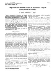
The structure of a hybrid stepper motor is depicted <strong>in</strong> Fig.<br />
1. The rotor consists of a cyl<strong>in</strong>drically shaped permanent<br />
magnet core magnetized along the cyl<strong>in</strong>der axis, whose<br />
poles are covered by two lam<strong>in</strong>ated soft steel toothed<br />
end-caps. Teeth <strong>in</strong> the two end-caps are misaligned with<br />
respect to each other by half a tooth pitch. The stator<br />
has typically eight poles, and each pole has between two<br />
and six teeth. The stator tooth pitch is usually equal<br />
to the rotor tooth pitch, but <strong>in</strong> some motors is a little<br />
larger to improve the position<strong>in</strong>g accuracy and reduce<br />
the detent torque. In a bipolar two-phase hybrid stepper<br />
motor (as considered <strong>in</strong> Sec. 2), two w<strong>in</strong>d<strong>in</strong>gs (phases)<br />
are alternatively arranged on the stator poles to form<br />
⋆ This work has been partially supported by the Programma<br />
Operativo F.S.E. 2007-2013 Regione Veneto, Codice Progetto<br />
2105/101/17/2214/2009 (”Modellizzazione Orientata al Controllo di<br />
Sistemi Meccatronici”).<br />
coils through which the flow of the permanent magnet<br />
flux can be enhanced or reduced. Successive coils of each<br />
phase are wound <strong>in</strong> opposite sense, so that the same phase<br />
current generates oppositely oriented magnetic fields <strong>in</strong><br />
opposite stator poles. Thanks to the skew arrangement<br />
of the rotor end-caps, the rotor moves <strong>in</strong> steps of a<br />
quarter of rotor tooth pitch when the two phases are<br />
excited with a conventional one-phase-on scheme (i.e. each<br />
phase is excited <strong>in</strong> turn with a positive or negative rated<br />
Fig. 1. Electromechanical structure of a hybrid stepper<br />
motor (after [Kenjo, 1984]).
current): hence, a f<strong>in</strong>e angular position<strong>in</strong>g resolution can<br />
be achieved with a sufficiently high number of rotor teeth.<br />
For example, <strong>in</strong> a motor with 50 rotor teeth (typical<br />
specification for several commercial products), the step<br />
length is 1.8 ◦ . Unfortunately, the generated torque is not<br />
smooth, be<strong>in</strong>g affected by undesired pulsations (harmonic<br />
components) that produce an irregular motion of the<br />
load. Non-smoothness of the generated torque becomes<br />
even more problematic <strong>in</strong> case of a resonant load, where<br />
the torque ripple could excite the load resonances, thus<br />
produc<strong>in</strong>g unacceptably large oscillations. Therefore, the<br />
reduction of torque ripple is highly desirable <strong>in</strong> many<br />
motion control applications.<br />
The adoption of a s<strong>in</strong>e-cos<strong>in</strong>e microstepp<strong>in</strong>g excitation<br />
scheme, <strong>in</strong> which the two phases are excited with two<br />
s<strong>in</strong>usoidal quadrature currents, is perhaps the most conventional<br />
strategy used to alleviate (but not def<strong>in</strong>itely remove)<br />
the torque ripple. Several other methods have been<br />
proposed <strong>in</strong> literature for reduc<strong>in</strong>g or compensat<strong>in</strong>g the<br />
torque ripple <strong>in</strong> permanent magnet synchronous motors -<br />
see [Jahns and Soong, 1996] and the references there<strong>in</strong>.<br />
However, the majority of the proposed methods requires<br />
a high resolution encoder for measur<strong>in</strong>g the rotor angular<br />
position on the load side. This requirement is obviously<br />
counter<strong>in</strong>tuitive <strong>in</strong> stepper motor applications, because of<br />
the <strong>in</strong>tr<strong>in</strong>sic open-loop nature of the actuator.<br />
In this paper, the problem of m<strong>in</strong>imiz<strong>in</strong>g the torque ripple<br />
<strong>in</strong>duced by uncalibrated offsets and amplitudes of the<br />
phase currents <strong>in</strong> a microstepp<strong>in</strong>g excitation scheme is considered.<br />
The proposed procedure is specifically conceived<br />
for f<strong>in</strong>d<strong>in</strong>g the optimal offset and amplitude compensation<br />
values by rely<strong>in</strong>g only on the acceleration measurements<br />
provided by a low–cost MEMS accelerometer placed on the<br />
load side. Compared to other exist<strong>in</strong>g solutions, the one<br />
proposed <strong>in</strong> this paper has the advantage of be<strong>in</strong>g <strong>in</strong>expensive<br />
and easily adaptable to exist<strong>in</strong>g systems. The paper is<br />
organized as follows. In Sec. 2 a model of the torque ripple<br />
generated by an HSM excited with a (unideal) microstepp<strong>in</strong>g<br />
scheme is presented; such model is then used <strong>in</strong> Sec.<br />
3 to describe the proposed m<strong>in</strong>imization procedure. The<br />
experimental results obta<strong>in</strong>ed with both an <strong>in</strong>ertial and a<br />
resonant load are reported <strong>in</strong> Sec. 4. F<strong>in</strong>ally, conclusions<br />
and future research directions are reported <strong>in</strong> Sec. 5.<br />
2. HSM TORQUE RIPPLE<br />
A bipolar two-phase permanent magnet (PM) hybrid stepper<br />
motor (HSM) is considered <strong>in</strong> the follow<strong>in</strong>g. An analytical<br />
expression of the generated torque can be obta<strong>in</strong>ed<br />
by apply<strong>in</strong>g the pr<strong>in</strong>ciple of energy conservation; under<br />
the simplify<strong>in</strong>g assumption that no magnetic saturation<br />
occurs <strong>in</strong> the magnetic circuit (i.e. the magnetic flux is<br />
proportional to the stator currents and <strong>in</strong>dependent of the<br />
<strong>in</strong>ternal magnet), it can be proved [Khorrami et al., 2003]<br />
that the motor torque τm, w.r.t. the rotor position θ, is<br />
equal to<br />
τm = 1<br />
2 iT ∂L<br />
i (1)<br />
∂θ<br />
where L is a 3 × 3 symmetric positive def<strong>in</strong>ite <strong>in</strong>ductance<br />
matrix<br />
<br />
L =<br />
L11 L12 L1f<br />
L12 L22 L2f<br />
L1f L2f Lff<br />
(2)<br />
and i = [i1, i2, if ] T , with i1, i2 the the w<strong>in</strong>d<strong>in</strong>g currents <strong>in</strong>,<br />
respectively, phase 1 and phase 2, and if is the constant<br />
fictitious field current used to describe the magnetic field<br />
produced by the permanent magnet. In the <strong>in</strong>ductance<br />
matrix, L11 and L22 are the self-<strong>in</strong>ductances of w<strong>in</strong>d<strong>in</strong>gs<br />
1 and 2, L12 is the mutual <strong>in</strong>ductance between the two<br />
w<strong>in</strong>d<strong>in</strong>gs, L1f and L2f are the mutual <strong>in</strong>ductances between<br />
the two w<strong>in</strong>d<strong>in</strong>gs and the fictitious rotor w<strong>in</strong>d<strong>in</strong>g, and Lff<br />
is the self-<strong>in</strong>ductance of the fictitious rotor w<strong>in</strong>d<strong>in</strong>g.<br />
The torque expression (1) can be expanded as follows<br />
<br />
∂L1f<br />
τm =τpm + τvr + τcg =<br />
∂θ i1if + ∂L2f<br />
∂θ i2if<br />
<br />
<br />
1 ∂L11<br />
+<br />
2 ∂θ i21 + 1 ∂L22<br />
2 ∂θ i22 + ∂L12<br />
∂θ i1i2<br />
<br />
+ 1 ∂Lff<br />
2 ∂θ i2f (3)<br />
The first term <strong>in</strong> round brackets is the torque component<br />
generated by the <strong>in</strong>teraction of the magnetic fields produced<br />
by the stator w<strong>in</strong>d<strong>in</strong>gs and the permanent magnet.<br />
The second term is the reluctance torque and depends<br />
on the variations <strong>in</strong> self and mutual <strong>in</strong>ductance of the<br />
w<strong>in</strong>d<strong>in</strong>gs (ma<strong>in</strong>ly due to geometric imperfections and rotor<br />
anisotropy). The last term is the cogg<strong>in</strong>g (or detent) torque<br />
and is ma<strong>in</strong>ly due to variations <strong>in</strong> self-<strong>in</strong>ductance of the<br />
fictitious rotor w<strong>in</strong>d<strong>in</strong>g caused by the presence of slots<br />
<strong>in</strong> the stator (m<strong>in</strong>imum reluctance path). The cogg<strong>in</strong>g<br />
torque is present even <strong>in</strong> absence of w<strong>in</strong>d<strong>in</strong>g currents; its<br />
periodicity with respect to the rotor position is equal to<br />
the periodicity at which the slots are located along the<br />
stator.<br />
All the entries of the <strong>in</strong>ductance matrix are periodic functions<br />
of the rotor position θ, and their basic frequencies can<br />
be deduced from the symmetries of the motor. Denot<strong>in</strong>g<br />
with Nr the number of rotor teeth, it holds that<br />
L11(θ) = L0 + L1 cos(2Nrθ) (4)<br />
L22(θ) = L0 − L1 cos(2Nrθ) (5)<br />
L12(θ) = − L0<br />
2 + L1 s<strong>in</strong>(2Nrθ) (6)<br />
n<br />
L1f (θ) = Lm0 + Lmj cos(jNrθ) (7)<br />
L2f (θ) = Lm0 +<br />
Lff (θ) = Lf0 +<br />
j=1<br />
n<br />
Lmj s<strong>in</strong>(jNrθ) (8)<br />
j=1<br />
n<br />
Lfj cos(jNrθ) (9)<br />
j=4<br />
where n is the number of harmonics considered <strong>in</strong> the<br />
expression of the motor torque. Higher order harmonics<br />
(n ≥ 2) <strong>in</strong> the mutual <strong>in</strong>ductance terms L1f and L2f<br />
model the nons<strong>in</strong>usoidal (with respect to the rotor angle)<br />
flux distribution <strong>in</strong> the airgap.<br />
In a typical (ideal) hybrid stepper motor, the variation<br />
of phase <strong>in</strong>ductance is as small as a few percent, and its<br />
contribution to the total torque is negligible; moreover, the<br />
surfaces of the rotor and stator teeth are shaped so that<br />
the magnetic flux <strong>in</strong> the airgap is almost s<strong>in</strong>usoidal.<br />
By sett<strong>in</strong>g<br />
L11 = L22 = L0, L12 = 0, Lmj = 0 j ≥ 2 (10)
<strong>in</strong> the self and mutual <strong>in</strong>ductances (4)−(9), and replac<strong>in</strong>g<br />
them <strong>in</strong> the torque components, (3) yields<br />
τpm = −i1if Lm1Nr s<strong>in</strong>(Nrθ) + i2if Lm1Nr cos(Nrθ) (11)<br />
τcg = − 1<br />
2<br />
and τvr = 0.<br />
n<br />
j=4<br />
LfjjNr s<strong>in</strong>(jNrθ)i 2 f<br />
(12)<br />
One way to generate an ideally constant torque consists of<br />
adopt<strong>in</strong>g a microstepp<strong>in</strong>g driv<strong>in</strong>g technique, <strong>in</strong> which two<br />
s<strong>in</strong>usoidal quadrature currents are imposed <strong>in</strong>to the stator<br />
w<strong>in</strong>d<strong>in</strong>gs:<br />
i1 = I cos(Nrθu) , i2 = I s<strong>in</strong>(Nrθu) (13)<br />
where θu is the angular position of the stator flux. In fact,<br />
replac<strong>in</strong>g (13) <strong>in</strong> (11) yields:<br />
τpm = if Lm1Nr I s<strong>in</strong> [Nr(θu − θ)] . (14)<br />
Hence, the torque τpm is constant whenever the angle<br />
ρ = θu − θ, called torque (or load) angle, is constant.<br />
In practice, due to unbalanc<strong>in</strong>g and imperfections of the<br />
driv<strong>in</strong>g amplifiers, the phase currents will always be affected<br />
by some offset, and their amplitude will be unmatched.<br />
By tak<strong>in</strong>g <strong>in</strong>to account the offsets and ga<strong>in</strong><br />
unbalanc<strong>in</strong>g <strong>in</strong> the expressions of phase currents, i.e.<br />
i1 = I10 + I11 cos(Nrθu) , i2 = I20 + I21 s<strong>in</strong>(Nrθu) (15)<br />
and replac<strong>in</strong>g them <strong>in</strong> (11) yields:<br />
<br />
1<br />
τpm = if Lm1Nr<br />
2 (I11 + I21) s<strong>in</strong>[Nr(θu − θ)]<br />
− I10 s<strong>in</strong>(Nrθ) + I20 cos(Nrθ)<br />
− 1<br />
2 (I11<br />
<br />
− I21) s<strong>in</strong>[Nr(θ + θu)]<br />
(16)<br />
For a constant torque angle ρ = θu − θ, two harmonic<br />
components show up <strong>in</strong> the torque τpm, <strong>in</strong> addition to a<br />
constant term. The first harmonic component of the torque<br />
ripple <strong>in</strong> τpm has the same frequency of the phase currents<br />
and an amplitude depend<strong>in</strong>g on the current offsets I10<br />
and I20; the second component has twice the frequency<br />
of the phase currents and an amplitude depend<strong>in</strong>g on the<br />
unbalanc<strong>in</strong>g of the phase current amplitudes I11 and I21.<br />
3. TORQUE RIPPLE MINIMIZATION IN HSMS<br />
Several methods have been proposed <strong>in</strong> literature for reduc<strong>in</strong>g<br />
or compensat<strong>in</strong>g the torque ripple <strong>in</strong> permanent<br />
magnet synchronous motors; a rather complete review is<br />
reported <strong>in</strong> [Jahns and Soong, 1996]. The methods can<br />
be broadly classified <strong>in</strong> two major categories: 1) methods<br />
based on the improvement of the mach<strong>in</strong>e design and<br />
the torque generation mechanism, and 2) methods based<br />
on the improvement of the excitation scheme, possibly<br />
exploit<strong>in</strong>g open or closed control loop schemes for compensat<strong>in</strong>g<br />
the nonideal characteristics of the mach<strong>in</strong>e.<br />
A well known design expedient to reduce the torque ripple<br />
<strong>in</strong> hybrid stepper motors consists of skew<strong>in</strong>g the two endcaps<br />
of the rotor by half the rotor tooth pitch. A review<br />
of many classical and <strong>in</strong>novative design techniques for<br />
smooth torque generation <strong>in</strong> PM motors are reported <strong>in</strong><br />
[Bianchi and Bolognani, 2002].<br />
Regard<strong>in</strong>g the second category of torque ripple m<strong>in</strong>imization<br />
methods, the most typical example is perhaps the<br />
so-called s<strong>in</strong>e-cos<strong>in</strong>e microstepp<strong>in</strong>g excitation scheme, <strong>in</strong><br />
which two s<strong>in</strong>usoidal quadrature currents are imposed to<br />
the stator w<strong>in</strong>d<strong>in</strong>gs. With such method, the magnetic<br />
flux generated by the stator rotates smoothly, thus reduc<strong>in</strong>g<br />
torque ripple and rotor oscillations. Nevertheless, the<br />
residual torque ripple could be still too large, especially <strong>in</strong><br />
presence of large cogg<strong>in</strong>g torque. In order to further reduce<br />
the torque ripple, a broad range of alternative techniques,<br />
based either on feedforward or feedback compensation<br />
schemes, have been proposed so far <strong>in</strong> literature.<br />
The usual feedforward compensation scheme consists of<br />
us<strong>in</strong>g programmed excitation waveforms for the phase<br />
currents to cancel the pulsat<strong>in</strong>g torque components. In the<br />
majority of the cases, the phase current profiles are shaped<br />
by <strong>in</strong>ject<strong>in</strong>g suitable harmonic components that selectively<br />
elim<strong>in</strong>ate the torque ripple components, similarly to what<br />
orig<strong>in</strong>ally proposed <strong>in</strong> [Le-Huy et al., 1986]. In [Favre<br />
et al., 1993], the compensat<strong>in</strong>g harmonics are determ<strong>in</strong>ed<br />
by employ<strong>in</strong>g an iterative procedure; <strong>in</strong> [Hung and D<strong>in</strong>g,<br />
1993], [Hanselman, 1994] and, more recently [Wu and<br />
Chapman, 2005], the current profiles for elim<strong>in</strong>at<strong>in</strong>g the<br />
torque ripple components up to a given harmonic order are<br />
computed <strong>in</strong> closed form by employ<strong>in</strong>g numerical optimization<br />
techniques, once the back emf waveforms are known.<br />
In [Ferretti et al., 1998], a compact model for the pulsat<strong>in</strong>g<br />
torque <strong>in</strong> PM motors is used to perform a feedforward<br />
compensation on the position controller output; the unknown<br />
parameters of the model are identified by perform<strong>in</strong>g<br />
simple closed-loop motion experiments. More advanced<br />
compensation schemes exploit adaptive [Chen and Paden,<br />
1993] or nonl<strong>in</strong>ear [Taylor, 1994], [Bodson et al., 1993]<br />
feedback control techniques to generate smoother torques.<br />
In any case, all the aforementioned solutions share the<br />
common drawback of requir<strong>in</strong>g the measurement of the<br />
rotor position: this is a rather restrictive assumption for<br />
stepper motor applications, where the actuator is specifically<br />
chosen to perform accurate position<strong>in</strong>g <strong>in</strong> open-loop,<br />
without requir<strong>in</strong>g any load-side position sensor (e.g. a high<br />
resolution encoder).<br />
3.1 Proposed scheme<br />
Differently from most of the solutions available <strong>in</strong> literature,<br />
the procedure for torque ripple reduction proposed <strong>in</strong><br />
this paper does not require any expensive high-resolution<br />
encoder for measur<strong>in</strong>g the rotor angular position; <strong>in</strong>stead,<br />
it makes use of a low-cost MEMS accelerometer to detect<br />
the vibration <strong>in</strong>duced by the torque ripple on the load-side.<br />
Apart from cost considerations, another advantage of the<br />
proposed solution is that it can be easily fitted <strong>in</strong> exist<strong>in</strong>g<br />
equipments, without requir<strong>in</strong>g substantial <strong>in</strong>terventions.<br />
The proposed procedure is conceived to m<strong>in</strong>imize the<br />
torque ripple contribution <strong>in</strong>duced by imperfections <strong>in</strong><br />
the generation of the current profiles when us<strong>in</strong>g a microstepp<strong>in</strong>g<br />
excitation scheme. As already mentioned <strong>in</strong><br />
Sec. 2, two imperfections are considered, namely undesired<br />
nonzero offsets <strong>in</strong> phase currents and unbalanced<br />
ga<strong>in</strong>s <strong>in</strong> the driv<strong>in</strong>g amplifiers of the two phases. The<br />
compensation scheme is based on the observation that,<br />
under the assumption made <strong>in</strong> Sec. 2, the nonzero current<br />
offsets produce a torque harmonic disturbance component<br />
at the same frequency of the driv<strong>in</strong>g currents, while the
amplitude unbalanc<strong>in</strong>g between the two current phases<br />
generates a second harmonic at twice the frequency of the<br />
driv<strong>in</strong>g currents.<br />
With reference to (16), it can be noted that the two torque<br />
ripple harmonics have magnitudes<br />
|τpm,1| = if Lm1Nr<br />
|τpm,2| = if Lm1Nr<br />
<br />
I 2 10 + I2 20<br />
(17)<br />
1<br />
4 |I11 − I21| (18)<br />
i.e. the squared magnitude of the first harmonic depends<br />
quadratically on the current offsets I10 and I20, while<br />
the squared magnitude of the second harmonic depends<br />
quadratically on the amplitude unbalanc<strong>in</strong>g I11 −I21. This<br />
observation allows to formulate a multi-step m<strong>in</strong>imization<br />
procedure, <strong>in</strong> which some current offsets and ga<strong>in</strong> unbalanc<strong>in</strong>g<br />
are deliberately <strong>in</strong>troduced <strong>in</strong> the phase currents,<br />
and then varied to seek for a m<strong>in</strong>imum of the amplitude of<br />
the first two harmonics of the acceleration ripple measured<br />
by the MEMS accelerometer.<br />
The procedure can be summarized <strong>in</strong> the follow<strong>in</strong>g steps:<br />
(1) do a first experiment <strong>in</strong> which the ideal microstepp<strong>in</strong>g<br />
excitation scheme (15) is modified as follows<br />
i1 = Î10 + I cos(Nrθu) , i2 = I s<strong>in</strong>(Nrθu) (19)<br />
where the offset Î10 is slowly varied over a specified<br />
range (fraction of the rated current I), while the rotor<br />
moves with almost constant velocity (i.e. while θu is<br />
slowly l<strong>in</strong>early <strong>in</strong>creased).<br />
By us<strong>in</strong>g a conventional synchronous amplitude demodulation<br />
scheme, extract the amplitude of the first<br />
harmonic of the acceleration ripple measured by the<br />
MEMS accelerometer.<br />
Then, use the (weighted) least squares method to<br />
fit a parabola to the data consist<strong>in</strong>g of the squared<br />
magnitude of the first harmonic vs. the values of the<br />
offset Î10: the m<strong>in</strong>imum of the parabolic fit gives the<br />
optimal offset compensation value Î∗ 10 for the phase<br />
current i1.<br />
(2) do a second experiment <strong>in</strong> which the previous step<br />
is repeated for the second phase current. Use the<br />
modified microstepp<strong>in</strong>g excitation scheme<br />
i1 = Î∗ 10 + I cos(Nrθu) , i2 = Î20 + I s<strong>in</strong>(Nrθu) (20)<br />
where the offset Î20 is slowly varied over a specified<br />
range. Obta<strong>in</strong> the optimal offset compensation value<br />
Î ∗ 20 by repeat<strong>in</strong>g the procedure described <strong>in</strong> the previous<br />
step.<br />
(3) do a third experiment <strong>in</strong> which the ideal microstepp<strong>in</strong>g<br />
excitation scheme (15) is modified as follows<br />
i1 = Î∗ 10 + Î11 cos(Nrθu) (21)<br />
i2 = Î∗ 20 + Î21 s<strong>in</strong>(Nrθu) (22)<br />
where Î11 is slowly varied over a specified range<br />
(across the rated current I), while Î21 = 2 I − Î11.<br />
The last condition guarantees that the average torque<br />
provided to the load dur<strong>in</strong>g the whole experiment is<br />
kept constant, despite the unbalanc<strong>in</strong>g of the phase<br />
current amplitudes - see equation (16).<br />
By us<strong>in</strong>g a conventional synchronous amplitude demodulation<br />
scheme, extract the amplitude of the sec-<br />
ond harmonic of the acceleration ripple measured by<br />
the MEMS accelerometer.<br />
Then, use the (weighted) least squares method to<br />
fit a parabola to the data consist<strong>in</strong>g of the squared<br />
magnitude of the second harmonic vs. the values<br />
of the current amplitude Î11: the m<strong>in</strong>imum of the<br />
parabolic fit gives the optimal amplitude value Î∗ 11<br />
for the phase current i1 (and, <strong>in</strong>directly, the optimal<br />
amplitude value Î∗ 21 for the phase current i2).<br />
In pr<strong>in</strong>ciple, the three steps described above can be iterated<br />
many times to ref<strong>in</strong>e the estimation of the optimal<br />
compensation values; however, it has been noted that a<br />
s<strong>in</strong>gle iteration is generally sufficient for atta<strong>in</strong><strong>in</strong>g the<br />
optimal values with a satisfactory accuracy level.<br />
4. EXPERIMENTAL RESULTS<br />
The proposed procedure for m<strong>in</strong>imiz<strong>in</strong>g the torque ripple<br />
<strong>in</strong> hybrid stepper motors has been tested on a commercial<br />
bipolar, two-phase HSM with 1.8 ◦ step angle (50 rotor<br />
teeth) driv<strong>in</strong>g either an <strong>in</strong>ertial or a resonant load. The<br />
<strong>in</strong>ertial load has been chosen as a steel disk with relatively<br />
small <strong>in</strong>ertia, mounted directly on the motor shaft; as for<br />
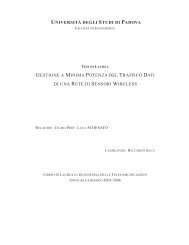
the resonant load, an elastic transmission system based on<br />
a pair of reduction gears (reduction ratio NG = 1/7) connected<br />
by a toothed belt has been considered (see Fig.2).<br />
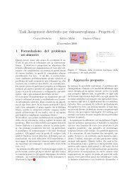
Such transmission system is part of the mechanism used<br />
for generat<strong>in</strong>g the pan and tilt motions <strong>in</strong> a position<strong>in</strong>g<br />
unit for surveillance cameras (see Fig.3).<br />
Fig. 2. Elastic transmission system composed of reduction<br />
gears and a toothed belt.<br />
S<strong>in</strong>ce the experimental results are similar for the <strong>in</strong>ertial<br />
and the resonant loads, only the latter are discussed <strong>in</strong> the<br />
rema<strong>in</strong><strong>in</strong>g part of this section, due to space constra<strong>in</strong>ts.<br />
The proposed procedure has been applied to reduce the<br />
vibration <strong>in</strong>duced by the motor torque ripple on the pan<br />
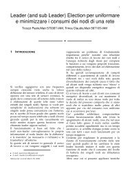
motion of the position<strong>in</strong>g unit. Therefore, a MEMS l<strong>in</strong>ear<br />
accelerometer has been placed on top of the camera, as<br />
shown <strong>in</strong> Fig. 4, to measure the tangential acceleration<br />
of the unit; then, the angular acceleration can be derived<br />
by measur<strong>in</strong>g the distance of the accelerometer from the<br />
rotation axis.<br />
Two s<strong>in</strong>usoidal phase currents with a nom<strong>in</strong>al amplitude<br />
of I = 1 A and a frequency of 20 Hz (correspond<strong>in</strong>g<br />
to an angular velocity of ≈ 21 ◦ /s for the pan motion)
Fig. 3. Position<strong>in</strong>g unit for surveillance cameras.<br />
Fig. 4. MEMS accelerometer placement on top of the<br />
camera case.<br />
have been used <strong>in</strong> the experiments. The driv<strong>in</strong>g frequency<br />
has been selected to avoid the excitation of the load<br />
resonances, thus generat<strong>in</strong>g a more regular motion <strong>in</strong><br />
which the acceleration variations produced by vary<strong>in</strong>g the<br />
current offsets/amplitudes can be highlighted more clearly.<br />
Due to an <strong>in</strong>accurate <strong>in</strong>itial calibration of the offsets and<br />
ga<strong>in</strong>s of the l<strong>in</strong>ear amplifiers used to drive the two motor<br />
phases, the phase currents are affected by some offset and<br />
ga<strong>in</strong> unbalanc<strong>in</strong>g, as shown <strong>in</strong> the top plot of Fig. 5.<br />
The application of the procedure described <strong>in</strong> the previous<br />
section yields the results collectively reported <strong>in</strong> Fig. 6.<br />
The two current offsets have been varied <strong>in</strong> the range<br />
−0.5 A ÷ 0.5 A (correspond<strong>in</strong>g to ±50% of the nom<strong>in</strong>al<br />
rated current I = 1 A); the m<strong>in</strong>imization of the first<br />
harmonic amplitude has been achieved with the offset<br />
values Î∗ 10 = −0.121 A and Î∗ 20 = −0.055 A (see the<br />
top plots of Fig. 6). The phase current amplitudes have<br />
been unbalanced up to 30 % of the nom<strong>in</strong>al rated current<br />
(i.e. the amplitude of one phase current has been varied<br />
<strong>in</strong> the range 0.7 A ÷ 1.3 A, while the rema<strong>in</strong><strong>in</strong>g one has<br />
been adjusted to keep the sum constant to 2 I = 2 A).<br />
The m<strong>in</strong>imization of the second harmonic amplitude is<br />
obta<strong>in</strong>ed with the amplitude values Î∗ 11 = 0.847 A and<br />
Î ∗ 21 = 2 I − Î∗ 11 = 1.153 A.<br />
It is worth notic<strong>in</strong>g that the measured square magnitudes<br />
of the first two acceleration harmonics depend quadratically<br />
on the two current offsets and the amplitude unbalanc<strong>in</strong>g,<br />
thus legitimat<strong>in</strong>g the assumptions made <strong>in</strong> Sec. 2<br />
for deriv<strong>in</strong>g the torque expression (16). However, differently<br />
from what could be argued by us<strong>in</strong>g (17) and (18),<br />
the measurements of the compensated currents reported<br />
<strong>in</strong> the bottom plot of Fig. 6 show that the torque ripple<br />
m<strong>in</strong>imization is atta<strong>in</strong>ed with some residual small offsets<br />
and ga<strong>in</strong> unbalanc<strong>in</strong>g.<br />
This discrepancy between the predicted and experimental<br />
results is expla<strong>in</strong>ed by the <strong>in</strong>ductance terms neglected<br />
<strong>in</strong> the derivation of (16), especially those describ<strong>in</strong>g the<br />
nons<strong>in</strong>usoidal flux distribution <strong>in</strong> the airgap (higher order<br />
harmonics <strong>in</strong> the mutual <strong>in</strong>ductance terms L1f and L2f ).<br />
The benefits of the proposed compensation procedure <strong>in</strong><br />
m<strong>in</strong>imiz<strong>in</strong>g the first two harmonics of the torque ripple<br />
Currents [A]<br />
Currents [A]<br />
Currents [A]<br />
Before compensation<br />
2<br />
1<br />
0<br />
-1<br />
-2<br />
0 0.2 0.4 0.6 0.8 1<br />
After offset compensation<br />
2<br />
1<br />
0<br />
-1<br />
-2<br />
0 0.2 0.4 0.6 0.8 1<br />
After offset and ga<strong>in</strong> compensations<br />
2<br />
1<br />
0<br />
-1<br />
-2<br />
0 0.2 0.4 0.6 0.8 1<br />
Time [s]<br />
Fig. 5. Phase currents measurements before and after the<br />
compensation procedure.<br />
Acceleration 2 [(rad/s 2 ) 2 ]<br />
0.8e6<br />
0.6e6<br />
0.4e6<br />
0.2e6<br />
Compensation offset: -0.121 A<br />
Measurement data<br />
Parabolic fitt<strong>in</strong>g<br />
Acceleration 2 [(rad/s 2 ) 2 ]<br />
Compensation offset: -0.055 A<br />
0.0e6<br />
-0.5 -0.25 0 0.25 0.5<br />
0.0e6<br />
-0.5 -0.25 0 0.25 0.5<br />
Current offset [A]<br />
Current offset [A]<br />
Compensation ga<strong>in</strong>: 0.847<br />
Acceleration 2 [(rad/s 2 ) 2 ]<br />
1.5e7<br />
1.0e7<br />
0.5e7<br />
0.0e7<br />
1.5e6<br />
1.0e6<br />
0.5e6<br />
0.8 1<br />
Ga<strong>in</strong><br />
1.2<br />
Fig. 6. Determ<strong>in</strong>ation of the optimal phase current offsets<br />
(top plots) and amplitude unbalanc<strong>in</strong>g (bottom plot).
Acceleration [rad/s 2 ]<br />
10000<br />
9000<br />
8000<br />
7000<br />
6000<br />
5000<br />
4000<br />
3000<br />
2000<br />
1000<br />
Acceleration FFT<br />
Initial situation<br />
After offset compensation<br />
After offset & ga<strong>in</strong> compensation<br />
0<br />
0 10 20 30 40 50 60 70 80 90<br />
Frequency [Hz]<br />
Fig. 7. Acceleration ripple (load-side) spectrum before and<br />
after the compensation procedure.<br />
can be also appreciated <strong>in</strong> the acceleration spectrum<br />
measurements reported <strong>in</strong> Fig. 7. The compensation of<br />
the current offsets drastically reduces the amplitude of the<br />
first harmonic (at 20 Hz); the m<strong>in</strong>imization of the second<br />
harmonic amplitude is less evident (at 40 Hz), perhaps due<br />
to the fact that the <strong>in</strong>itial ga<strong>in</strong>s of the driv<strong>in</strong>g amplifiers<br />
were almost balanced before apply<strong>in</strong>g the compensation<br />
procedure.<br />
5. CONCLUSIONS<br />
This paper has presented a procedure for m<strong>in</strong>imiz<strong>in</strong>g the<br />
torque ripple <strong>in</strong>duced <strong>in</strong> HSMs by uncalibrated offsets and<br />
amplitudes of the phase currents generated with a microstepp<strong>in</strong>g<br />
driver. The proposed method relies exclusively<br />
on the acceleration measurement provided by a low–cost<br />
MEMS accelerometer placed on the load–side: no highresolution,<br />
expensive encoders are needed for measur<strong>in</strong>g<br />
the rotor position, as usually required <strong>in</strong> many compensation<br />
schemes available <strong>in</strong> literature. The effectiveness of<br />
the proposed solution has been experimentally proved, <strong>in</strong><br />
both the cases of an <strong>in</strong>ertial and a resonant load.<br />
Some (experimentally validated) work<strong>in</strong>g assumptions<br />
have been considered for the def<strong>in</strong>ition of the compensation<br />
procedure: <strong>in</strong> particular, the effects of the reluctance<br />
torque and the nons<strong>in</strong>usoidal flux distribution <strong>in</strong> the airgaps<br />
have been almost neglected.<br />
A future development of the present work consists of<br />
understand<strong>in</strong>g how the neglected terms (such as the reluctance<br />
torque and high order harmonic components <strong>in</strong><br />
the cogg<strong>in</strong>g torque) affect the torque ripple, and how they<br />
can be effectively <strong>in</strong>cluded <strong>in</strong> the m<strong>in</strong>imization procedure.<br />
6. ACKNOWLEDGEMENTS<br />
The authors would like to thank Videotec (Schio, Vicenza,<br />
Italy) for provid<strong>in</strong>g (and allow us to hack) the camera<br />
position<strong>in</strong>g units, and Andrea Parisotto, Daniele Pellizzer,<br />
Marco Peruzzo and Mattia Schiesaro for their valuable<br />
contribution to the experimental activity.<br />
REFERENCES<br />
N. Bianchi and S. Bolognani. Design techniques for<br />
reduc<strong>in</strong>g the cogg<strong>in</strong>g torque <strong>in</strong> surface-mounted PM<br />
motors. Industry Applications, IEEE Transactions on,<br />
38(5):1259 – 1265, sep. 2002. ISSN 0093-9994. doi:<br />
10.1109/TIA.2002.802989.<br />
M. Bodson, J.N. Chiasson, R.T. Novotnak, and R.B.<br />
Rekowski. High-performance nonl<strong>in</strong>ear feedback control<br />
of a permanent magnet stepper motor. Control Systems<br />
Technology, IEEE Transactions on, 1(1):5 –14, mar.<br />
1993.<br />
D. Chen and B. Paden. Adaptive l<strong>in</strong>earization of hybrid<br />
step motors: stability analysis. Automatic Control,<br />
IEEE Transactions on, 38(6):874 –887, jun. 1993. ISSN<br />
0018-9286. doi: 10.1109/9.222300.<br />
E. Favre, L. Cardoletti, and M. Jufer. Permanent-magnet<br />
synchronous motors: a comprehensive approach to cogg<strong>in</strong>g<br />
torque suppression. Industry Applications, IEEE<br />
Transactions on, 29(6):1141 –1149, nov. 1993. ISSN<br />
0093-9994. doi: 10.1109/28.259725.<br />
G. Ferretti, G. Magnani, and P. Rocco. Model<strong>in</strong>g, identification,<br />
and compensation of pulsat<strong>in</strong>g torque <strong>in</strong> permanent<br />
magnet AC motors. Industrial Electronics, IEEE<br />
Transactions on, 45(6):912 –920, dec. 1998. ISSN 0278-<br />
0046. doi: 10.1109/41.735335.<br />
D.C. Hanselman. M<strong>in</strong>imum torque ripple, maximum efficiency<br />
excitation of brushless permanent magnet motors.<br />
Industrial Electronics, IEEE Transactions on,<br />
41(3):292 –300, jun. 1994. ISSN 0278-0046. doi:<br />
10.1109/41.293899.<br />
J.Y. Hung and Z. D<strong>in</strong>g. Design of currents to reduce torque<br />
ripple <strong>in</strong> brushless permanent magnet motors. Electric<br />
Power Applications, IEE Proceed<strong>in</strong>gs B, 140(4):260 –<br />
266, jul. 1993. ISSN 0143-7038.<br />
T.M. Jahns and W.L. Soong. Pulsat<strong>in</strong>g torque m<strong>in</strong>imization<br />
techniques for permanent magnet AC motor drivesa<br />
review. Industrial Electronics, IEEE Transactions<br />
on, 43(2):321 –330, apr. 1996. ISSN 0278-0046. doi:<br />
10.1109/41.491356.<br />
T. Kenjo. Stepp<strong>in</strong>g <strong>Motors</strong> and Their Microprocessor<br />
Controls. Clarendon Press, Oxford, 1984.<br />
F. Khorrami, P. Krishnamurthy, and H. Melkote. Model<strong>in</strong>g<br />
and adaptive nonl<strong>in</strong>ear control of electric motors.<br />
Spr<strong>in</strong>ger-Verlag, Berl<strong>in</strong>, 2003.<br />
Hoang Le-Huy, Robert Perret, and Rene Feuillet. <strong>M<strong>in</strong>imization</strong><br />
of <strong>Torque</strong> <strong>Ripple</strong> <strong>in</strong> Brushless DC Motor<br />
Drives. Industry Applications, IEEE Transactions on,<br />
IA-22(4):748 –755, jul. 1986. ISSN 0093-9994. doi:<br />
10.1109/TIA.1986.4504787.<br />
D.G. Taylor. Nonl<strong>in</strong>ear control of electric mach<strong>in</strong>es: an<br />
overview. Control Systems Magaz<strong>in</strong>e, IEEE, 14(6):41 –<br />
51, dec. 1994. ISSN 0272-1708. doi: 10.1109/37.334414.<br />
A.P. Wu and P.L. Chapman. Simple expressions for<br />
optimal current waveforms for permanent-magnet synchronous<br />
mach<strong>in</strong>e drives. Energy Conversion, IEEE<br />
Transactions on, 20(1):151 – 157, mar. 2005. ISSN 0885-<br />
8969. doi: 10.1109/TEC.2004.837299.