APTA RP-E-016-99 Recommended Practice for - APTAStandards.com
APTA RP-E-016-99 Recommended Practice for - APTAStandards.com
APTA RP-E-016-99 Recommended Practice for - APTAStandards.com
Create successful ePaper yourself
Turn your PDF publications into a flip-book with our unique Google optimized e-Paper software.
<strong>APTA</strong> <strong>RP</strong>-E-<strong>016</strong>-<strong>99</strong><br />
Edited 3-22-04<br />
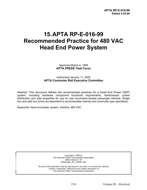
15. <strong>APTA</strong> <strong>RP</strong>-E-<strong>016</strong>-<strong>99</strong><br />
<strong>Re<strong>com</strong>mended</strong> <strong>Practice</strong> <strong>for</strong> 480 VAC<br />
Head End Power System<br />
Approved March 4, 1<strong>99</strong>9<br />
<strong>APTA</strong> PRESS Task Force<br />
Authorized January 11, 2000<br />
<strong>APTA</strong> Commuter Rail Executive Committee<br />
Abstract: This document defines the re<strong>com</strong>mended practices <strong>for</strong> a Head End Power (HEP)<br />
system, including hardware <strong>com</strong>ponent functional requirements, transmission, power<br />
distribution and load properties <strong>for</strong> use on new lo<strong>com</strong>otive-hauled passenger vehicles. Single<br />
bus and split bus <strong>for</strong>ms are described to ac<strong>com</strong>modate intercity and <strong>com</strong>muter type operations.<br />
Keywords: head end power system, trainline, 480 VAC<br />
Copyright © 1<strong>99</strong>9 by<br />
The American Public Transportation Association<br />
1666 K Street, N. W.<br />
Washington, DC, 20006, USA<br />
No part of this publication may be reproduced in any <strong>for</strong>m, in an electronic retrieval<br />
system or otherwise, without the prior written permission of<br />
The American Public Transportation Association.<br />
15.0<br />
Volume III – Electrical
Participants<br />
15.1<br />
<strong>APTA</strong> <strong>RP</strong>-E-<strong>016</strong>-<strong>99</strong><br />
Edited 3-22-04<br />
The American Public Transportation Association greatly appreciates the contributions of the<br />
following individual(s), who provided the primary ef<strong>for</strong>t in the drafting of the <strong>Re<strong>com</strong>mended</strong><br />
<strong>Practice</strong> <strong>for</strong> 480 VAC Head End Power System.<br />
Dick Bruss<br />
At the time that this re<strong>com</strong>mended practice was <strong>com</strong>pleted, the PRESS Electrical Committee<br />
included the following members:<br />
Gilbert L. Bailey<br />
Brad Barkman<br />
Ronald Bartels<br />
Richard Benjamin<br />
Dick Bruss<br />
Daniel L. Davis<br />
James Dietz<br />
Dave Elliott<br />
Hassan A. Fazli<br />
Bert Gagne<br />
Peter Hale<br />
Carl C. Herrmann<br />
Doug Warner, Chair<br />
Stephen Hilbert<br />
LeRoy D. Jones<br />
Brian Ley<br />
Otto Masek<br />
Rich Mazur<br />
Chuck Olson<br />
David Phelps<br />
Craig Prudian<br />
George Scerbo<br />
Ike Tingos<br />
Steve Zuiderveen<br />
Volume III – Electrical
Contents<br />
15.2<br />
<strong>APTA</strong> <strong>RP</strong>-E-<strong>016</strong>-<strong>99</strong><br />
Edited 3-22-04<br />
1. Overview..............................................................................................................................................15.4<br />
1.1 Scope .............................................................................................................................................15.4<br />
1.2 Purpose ..........................................................................................................................................15.4<br />
2. References............................................................................................................................................15.4<br />
3. Definitions abbreviations and acronyms..............................................................................................15.5<br />
3.1 Definitions .....................................................................................................................................15.5<br />
4. General.................................................................................................................................................15.7<br />
4.1 Purpose of HEP (Head End Power)...............................................................................................15.7<br />
4.2 Power sources................................................................................................................................15.7<br />
4.3 HEP trainline configurations .........................................................................................................15.7<br />
4.4 Single bus HEP system attributes..................................................................................................15.8<br />
4.5 Split bus HEP system attributes.....................................................................................................15.8<br />
4.6 Transmission capacity ...................................................................................................................15.9<br />
4.7 Environment ..................................................................................................................................15.9<br />
5. Application to vehicles ...................................................................................................................... 15.10<br />
5.1 End location (left/right) ............................................................................................................... 15.10<br />
5.2 Mounting ..................................................................................................................................... 15.10<br />
5.3 Identification................................................................................................................................ 15.10<br />
5.4 Control junction boxes................................................................................................................. 15.11<br />
5.5 Power junction boxes................................................................................................................... 15.11<br />
5.6 Wire routing................................................................................................................................. 15.11<br />
6. Transmission system <strong>com</strong>ponents...................................................................................................... 15.12<br />
6.1 Receptacle and jumper cable re<strong>com</strong>mended practices ................................................................ 15.12<br />
6.2 Car cabling................................................................................................................................... 15.12<br />
6.3 HEP power junction box.............................................................................................................. 15.13<br />
6.4 Control junction box.................................................................................................................... 15.13<br />
7. Trainline <strong>com</strong>plete control (TLC)...................................................................................................... 15.14<br />
7.1 General ........................................................................................................................................ 15.14<br />
7.2 TLC trainline function of a train.................................................................................................. 15.14<br />
7.3 Active sources.............................................................................................................................. 15.14<br />
7.4 Indicator lights............................................................................................................................. 15.15<br />
7.5 TLC trainline function from wayside ..........................................................................................15.15<br />
8. Load characteristics ........................................................................................................................... 15.15<br />
8.1 Load type ..................................................................................................................................... 15.15<br />
8.2 Maximum load............................................................................................................................. 15.15<br />
8.3 Phase rotation .............................................................................................................................. 15.15<br />
8.4 Phase balance............................................................................................................................... 15.15<br />
Volume III – Electrical
<strong>APTA</strong> <strong>RP</strong>-E-<strong>016</strong>-<strong>99</strong><br />
Edited 3-22-04<br />
8.5 Voltage range............................................................................................................................... 15.15<br />
8.6 Frequency range .......................................................................................................................... 15.16<br />
8.7 Primary loads............................................................................................................................... 15.16<br />
8.8 Secondary loads........................................................................................................................... 15.16<br />
8.9 Staggered start ............................................................................................................................. 15.16<br />
8.10 Power interruption ..................................................................................................................... 15.16<br />
8.11 Isolation from HEP bus ............................................................................................................. 15.17<br />
8.12 Primary power distribution........................................................................................................ 15.17<br />
8.13 Branch circuit breakers.............................................................................................................. 15.17<br />
9. Testing ............................................................................................................................................... 15.17<br />
9.1 Wiring.......................................................................................................................................... 15.17<br />
9.2 Proof-of-design............................................................................................................................ 15.18<br />
10. List of diagrams and illustrations..................................................................................................... 15.18<br />
15.3<br />
Volume III – Electrical
<strong>APTA</strong> <strong>RP</strong>-E-<strong>016</strong>-<strong>99</strong><br />
Edited 3-22-04<br />
<strong>APTA</strong> <strong>RP</strong>-E-<strong>016</strong>-<strong>99</strong><br />
<strong>Re<strong>com</strong>mended</strong> <strong>Practice</strong> <strong>for</strong> 480 VAC Head End Power<br />
System<br />
1. Overview<br />
1.1 Scope<br />
This document defines the re<strong>com</strong>mended practices <strong>for</strong> a Head End Power (HEP) system,<br />
including hardware <strong>com</strong>ponent functional requirements, transmission, power distribution and<br />
load properties <strong>for</strong> use on new lo<strong>com</strong>otive-hauled passenger vehicles. Single bus and split bus<br />
<strong>for</strong>ms are described to ac<strong>com</strong>modate intercity and <strong>com</strong>muter type operations.<br />
This document covers HEP Vehicle <strong>Re<strong>com</strong>mended</strong> <strong>Practice</strong>s; document <strong>APTA</strong> <strong>RP</strong>-E-018-<strong>99</strong><br />
covers associated HEP Jumper and Receptacle Hardware <strong>Re<strong>com</strong>mended</strong> <strong>Practice</strong>s.<br />
1.2 Purpose<br />
The purpose of this document is to define the re<strong>com</strong>mended practices <strong>for</strong> HEP systems,<br />
including vehicle interface and the electrical source, transmission and load characteristics<br />
required to allow intermixing of cars and lo<strong>com</strong>otives of varying designs. In addition, it defines<br />
minimum HEP system construction re<strong>com</strong>mended practices <strong>for</strong> new equipment.<br />
Equipment con<strong>for</strong>ming to this re<strong>com</strong>mended practice should be mutually <strong>com</strong>patible <strong>for</strong> HEP<br />
operation (with some limitations, as described in section 4.3).<br />
For special functions not already in general use, it is re<strong>com</strong>mended that the specifying entity, be<br />
it an authority or railroad, approach <strong>APTA</strong> <strong>for</strong> a re<strong>com</strong>mendation as to how to address the<br />
property-specific functions.<br />
When new equipment specifications are under development, it is highly advisable that the<br />
writer(s) carefully review the trainline control system requirements (both electrical and<br />
mechanical) with the specifying entity (which will <strong>for</strong> convenience herein be called an<br />
“authority”; “railroad” will be used to indicate the operating, as opposed to specifying, entity) to<br />
identify any subtle issues that may not be contained in this document.<br />
2. References<br />
<strong>APTA</strong> SS-E-001-98, Standard <strong>for</strong> Insulation Integrity<br />
<strong>APTA</strong> <strong>RP</strong>-E-002-98, <strong>Re<strong>com</strong>mended</strong> <strong>Practice</strong> <strong>for</strong> Wiring of Passenger Equipment<br />
<strong>APTA</strong> <strong>RP</strong>-E-009-98, <strong>Re<strong>com</strong>mended</strong> <strong>Practice</strong> <strong>for</strong> Wire Used on Passenger Rolling Stock<br />
<strong>APTA</strong> <strong>RP</strong>-E-011-98, <strong>Re<strong>com</strong>mended</strong> <strong>Practice</strong> <strong>for</strong> Head End Power Load Testing<br />
<strong>APTA</strong> <strong>RP</strong>-E-015-<strong>99</strong>, <strong>Re<strong>com</strong>mended</strong> <strong>Practice</strong> <strong>for</strong> Head End Power Source Characteristics<br />
15.4<br />
Volume III – Electrical
<strong>APTA</strong> <strong>RP</strong>-E-<strong>016</strong>-<strong>99</strong><br />
Edited 3-22-04<br />
<strong>APTA</strong> <strong>RP</strong>-E-018-00, <strong>Re<strong>com</strong>mended</strong> <strong>Practice</strong> <strong>for</strong> 480 VAC Head End Power Jumper and<br />
Receptacle Hardware.<br />
49 CFR 229.85 Doors and cover plates marked “Danger”<br />
49 CFR 238.303.12 Marking of door and cover plate guarding High Voltage Equipment.<br />
3. Definitions abbreviations and acronyms<br />
3.1 Definitions<br />
For the purpose of this re<strong>com</strong>mended practice the following definitions apply.<br />
3.1.1 car control: For the purposes of this re<strong>com</strong>mended practice, car control is those trainlined<br />
<strong>com</strong>munication functions associated with lo<strong>com</strong>otive-hauled passenger cars, e.g. door control,<br />
public address, etc.<br />
3.1.2 dead bus protection: Dead bus protection is a control system feature that confirms that<br />
the HEP bus is not energized (dead bus) be<strong>for</strong>e allowing the local HEP output contactor to close.<br />
This prevents inadvertently connecting two HEP sources to the same bus.<br />
3.1.3 fixed jumper: A fixed jumper is a variation of a HEP jumper cable in which only one end<br />
is provided with a plug, while the remaining end is provided with a flange <strong>for</strong> mounting on a<br />
vehicle. This approach is taken to permanently affix the jumper to the vehicle and reduce the<br />
number of contacts, since they are only present on one end rather than two.<br />
3.1.4 head end power (HEP): A system by which 480 VAC 3-phase electrical power, to<br />
operate auxiliaries, is provided to railroad vehicles from a central source via a trainline system.<br />
The power source can be lo<strong>com</strong>otive (hence "Head End"), power car, or wayside source.<br />
3.1.5 HEP jumper cable: A HEP jumper cable is a cable assembly, having the necessary power<br />
and control conductors and equipped with a plug on one or both ends, which is used to provide a<br />
flexible electrical connection between two cars and/or lo<strong>com</strong>otives or wayside equipment.<br />
3.1.6 HEP receptacles: The receptacles mounted on the ends of rail vehicles and wayside<br />
equipment into which the HEP jumper cables mate.<br />
3.1.7 HEP source: A source of Head End Power, contained in a lo<strong>com</strong>otive, power car or from<br />
a wayside power connection.<br />
3.1.8 HEP switchgear: The contractors, circuit breakers, power switches, overload protection<br />
and associated control <strong>com</strong>ponents used to connect the HEP power source to the trainline<br />
system.<br />
3.1.9 HEP system, single bus: A <strong>for</strong>m of HEP transmission system in which there is a single<br />
electrical bus running the length of the train. All four jumpers connecting adjacent vehicles are<br />
wired in parallel.<br />
3.1.10 HEP system, split bus: Split bus is a <strong>for</strong>m of HEP transmission system in which there<br />
are two independent electrical buses running the length of the train, a train left and train right<br />
(relative to the <strong>for</strong>ward direction of the train). The buses may be fed HEP independently from<br />
15.5<br />
Volume III – Electrical
<strong>APTA</strong> <strong>RP</strong>-E-<strong>016</strong>-<strong>99</strong><br />
Edited 3-22-04<br />
separate sources, such as two lo<strong>com</strong>otives. Two of the jumpers connecting vehicles are wired in<br />
parallel to the left bus, and two to the right bus. Vehicle loads may be divided and isolated from<br />
each other so as to take some power from each bus.<br />
3.1.11 HEP trainline: The HEP trainline is an electrical cable system which allows HEP to be<br />
transmitted over the entire length of a train. It includes both power and control conductors. The<br />
trainline may provide power to equipment in each vehicle, or may simply pass straight through,<br />
providing a power path between vehicles on opposite ends of that vehicle.<br />
3.1.12 load box: A load box is a piece of wayside equipment used to provide a test load <strong>for</strong> an<br />
HEP source to allow its per<strong>for</strong>mance to be measured. The equipment consists of a variable<br />
resistance load, cooling fan, load control switching, control panel and instrumentation.<br />
3.1.13 looping: Looping is the process of connecting a jumper cable between two adjacent<br />
receptacles (or a fixed jumper and an adjacent receptacle) on the same vehicle. This is normally<br />
done on the exposed end of the first and last vehicles of a train and establishes the trainline<br />
<strong>com</strong>plete circuit. Lo<strong>com</strong>otives having the F-end HEP receptacles disconnected through the use<br />
of an isolation switch use an internal loop circuit and do not require an F-end loop.<br />
When wayside power is applied via the end of the consist, the opposite, far end of the train is<br />
looped in the normal fashion. At the near end, a loop is put between left and right sides of the<br />
train and the wayside power is connected with one jumper to the right and one jumper to the left<br />
side of the train.<br />
3.1.14 MU (multiple unit): A system of simultaneous control of all lo<strong>com</strong>otive units in a<br />
consist from one master controller through the means of trainlines.<br />
3.1.15 portable jumper: A portable jumper is a <strong>for</strong>m of a HEP jumper cable in which both ends<br />
are provided with plugs. This approach is taken to allow the jumper cable to be easily removed<br />
from the vehicle and moved elsewhere.<br />
3.1.16 power car: For purposes of this document, a power car is a rail vehicle, other than a<br />
lo<strong>com</strong>otive, containing a HEP source and control system. This generally takes the <strong>for</strong>m of a<br />
baggage car or a car converted from a lo<strong>com</strong>otive that has had the traction system removed.<br />
3.1.17 short looping: Short looping is the process of looping the HEP jumpers at points other<br />
than the ends of the train. This is used in an emergency situation such as over<strong>com</strong>ing a damaged<br />
jumper on the road, to bypass an open trainline <strong>com</strong>plete circuit on one side of the train.<br />
CAUTION - When short looped, vehicles behind the short loop site do not have the TLC indication or control<br />
interlock at the HEP controls, even though the 480 volt circuits may be live.<br />
3.1.18 trainline <strong>com</strong>plete (TLC): The trainline <strong>com</strong>plete circuit is a series continuity check,<br />
originating at the HEP control system, used to determine that all HEP trainline jumper cables<br />
throughout the entire length of the consist are plugged in correctly. The circuit provides an<br />
indication at the HEP control panel and is interlocked with the HEP main contactor/circuit<br />
breaker to allow the trainlines to be energized only when the TLC circuit is established.<br />
CAUTION The practice of short looping will negate the TLC protection and is generally prohibited except<br />
when absolutely necessary to protect the health and well being of passengers.<br />
15.6<br />
Volume III – Electrical
<strong>APTA</strong> <strong>RP</strong>-E-<strong>016</strong>-<strong>99</strong><br />
Edited 3-22-04<br />
3.1.19 wayside power: Wayside power is an installation which provides HEP from a groundbased<br />
source, used to provide power to the consist when the on-board source is unavailable, such<br />
as in a yard. Generally, utility power is used, though sometimes a diesel generator is provided.<br />
4. General<br />
4.1 Purpose of HEP (Head End Power)<br />
The concept of HEP provides a convenient means by which electrical power (up to about 1<br />
Megawatt) can be generated by a central source and transmitted to each car throughout a train<br />
consist to operate auxiliary equipment. Typical HEP loads consist of HVAC, lighting, battery<br />
charging/low voltage power supply, food service equipment and water heating equipment.<br />
4.2 Power sources<br />
There are four source configurations <strong>for</strong> HEP:<br />
– Alternator driven from lo<strong>com</strong>otive traction prime mover<br />
– Alternator driven from dedicated engine<br />
– Lo<strong>com</strong>otive inverter<br />
– Wayside power (stationary utility)<br />
The HEP system source should be <strong>com</strong>prised of:<br />
– Power source<br />
– Switchgear (on-off as well as overload and other protection)<br />
– Control system incorporating Trainline Complete (TLC) functions<br />
– Connections to vehicle HEP trainline<br />
Refer to <strong>APTA</strong> <strong>RP</strong>-E-015-<strong>99</strong>, Head End Power Source Characteristics, <strong>for</strong> HEP source details.<br />
4.3 HEP trainline configurations<br />
Two alternative approaches <strong>for</strong> the HEP trainline system are available: Single and Split Bus.<br />
4.3.1 Single bus<br />
Single Bus is used on some <strong>com</strong>muter equipment and all intercity equipment. (Except on VIA<br />
which uses Split Bus.) The single bus system is re<strong>com</strong>mended, primarily on considerations of<br />
lower first cost, less <strong>com</strong>plexity, more widespread usage, and increased operational flexibility.<br />
4.3.2 Split bus<br />
Split Bus allows the train to be fed from two independent HEP sources simultaneously, which<br />
may allow larger consist power demand. Split bus is used on some <strong>com</strong>muter equipment.<br />
15.7<br />
Volume III – Electrical
4.3.3 Intermixing<br />
15.8<br />
<strong>APTA</strong> <strong>RP</strong>-E-<strong>016</strong>-<strong>99</strong><br />
Edited 3-22-04<br />
Individual railroad rules and operating practices govern the intermixing of single and split bus<br />
equipment. However, <strong>for</strong> purposes of this document, the alternative approaches are semi<strong>com</strong>patible<br />
as follows:<br />
– Single Bus source can feed a consist containing either Single Bus, Split Bus, or a mix of<br />
both bus arrangements<br />
– Split Bus source can only feed a Split bus consist<br />
– Single Bus and Split Bus equipment can be intermixed within a consist provided the HEP<br />
source is Single Bus and both Split Buses are utilized throughout the length of the<br />
consist.<br />
4.4 Single bus HEP system attributes<br />
– One HEP bus the length of the train<br />
– 480 VAC, 3 Phase, 3-wire, ungrounded system, 60 Hz operation<br />
– (The source may have a neutral ground reference, but the distribution system and load do<br />
not.)<br />
– 1600 Amp continuous rating<br />
– 4 jumpers across each car-car-lo<strong>com</strong>otive connection (see Figure 1)<br />
– All 4 jumpers in parallel<br />
– Power schematic (see Figures 2 and 3)<br />
– Control schematic (see Figures 6 and 7)<br />
– Jumper cable end arrangement on vehicle (see Figures 8 through 11)<br />
– Single HEP power junction box<br />
– Single HEP tap to feed each car<br />
4.5 Split bus HEP system attributes<br />
– Two HEP buses the length of the train, one on each side<br />
– 480 VAC, 3 Phase, 3-wire, ungrounded system, 60 Hz operation<br />
– (The source may have a neutral ground reference, but the distribution system and load do<br />
not.)<br />
– 800 Amp continuous rating per bus<br />
– 4 jumpers across each car-car-lo<strong>com</strong>otive connection (see Figure 1)<br />
Volume III – Electrical
– 2 jumpers in parallel <strong>for</strong> left bus, 2 jumpers in parallel <strong>for</strong> right bus<br />
– Power schematic (see Figures 4 and 5)<br />
– Control schematic (see Figures 6 and 7)<br />
– Jumper cable end arrangement on vehicle (see Figures 8 through 11)<br />
– Two HEP power junction boxes<br />
– Two HEP taps to feed each car, one from each bus<br />
4.6 Transmission capacity<br />
15.9<br />
<strong>APTA</strong> <strong>RP</strong>-E-<strong>016</strong>-<strong>99</strong><br />
Edited 3-22-04<br />
The entire HEP trainline system should be rated <strong>for</strong> continuous service over the outside ambient<br />
of –40 to +110 degrees F (-40 to +43 degrees C), unless otherwise specified by the authority.<br />
Single bus: 1600 Amps<br />
Split bus: 800 Amps per each bus<br />
To minimize voltage drop, cable resistance, including jumper cables and no more than four (4)<br />
bolted connections, should not exceed:<br />
Single bus: equivalent to 125% of car length of 12-4/0 cables, 4 per phase<br />
Split bus: equivalent to 125% of car length of 6-4/0 cables, 2 per phase.<br />
4.7 Environment<br />
The equipment should be suitably rated <strong>for</strong> the mechanical conditions experienced on the<br />
vehicle, especially shock, vibration and ambient temperatures. As these conditions are site and<br />
vehicle specific, they should be specified by the authority in contract specification documents.<br />
The following are examples of conditions which may occur and should be the subject of such<br />
detailed specifications:<br />
– Heavy rain, driven by wind or water from a hose<br />
– Hail, ice, powdered snow<br />
– Blown sand, dust, ballast and rocks<br />
– Vehicle speeds to 125 mph (200 km/hr)<br />
– Wind gusts to 90 mph (145 km/hr)<br />
– Salt (sea spray or from roads during winter months)<br />
– Impact from airborne road debris<br />
– Car washing chemicals and wash rack operations<br />
Volume III – Electrical
5. Application to vehicles<br />
5.1 End location (left/right)<br />
15.10<br />
<strong>APTA</strong> <strong>RP</strong>-E-<strong>016</strong>-<strong>99</strong><br />
Edited 3-22-04<br />
The location of the receptacles on the end of the vehicle should con<strong>for</strong>m to Figures 8 through 11.<br />
5.1.1 Lo<strong>com</strong>otives<br />
Receptacles or fixed jumpers with receptacles should be provided on all four corners of each<br />
vehicle. Fixed jumpers should be provided at the non-cab end.<br />
5.1.2 Power cars<br />
Receptacles or fixed jumpers with receptacles should be provided at all four corners of each<br />
vehicle. Fixed jumpers should be provided at the non-cab end.<br />
5.1.3 Cars<br />
Receptacles and fixed jumpers should be provided at all four corners of each vehicle, with fixed<br />
jumper cables installed in positions #1 and #3 at both ends.<br />
5.2 Mounting<br />
The plate to which the receptacles (and fixed jumper flanges, if used) are mounted should be<br />
rein<strong>for</strong>ced to resist, without bending, <strong>for</strong>ces produced from pulling the locked jumper out of the<br />
receptacle, such as by an unintended uncoupling. The jumper cable should be sacrificial relative<br />
to the carbody <strong>com</strong>ponents.<br />
Receptacle mounting should be such that there is adequate clearance between jumpers,<br />
receptacles and uncoupling rods, diaphragm/ buffer, coupler, air hoses, etc. Variables include:<br />
• Coupler motion horizontally and vertically<br />
• Relative motion to adjacent vehicle, in curve, passing through crossover, in buff and<br />
draft, etc.<br />
• Whether jumper is inserted into receptacle or not<br />
There should be no interference that restricts opening the receptacle cover fully to allow insertion<br />
or withdrawal of jumpers.<br />
5.3 Identification<br />
As an identification aid, receptacle housings should be color-coded red and labeled as follows:<br />
"Danger 480 V"<br />
Warning labels should be provided, consistent with FRA regulations 49 CFR 229.085 and 49<br />
CFR 238.303.12 1 .<br />
1 For references in Italics, see Section 2.<br />
Volume III – Electrical
5.4 Control junction boxes<br />
15.11<br />
<strong>APTA</strong> <strong>RP</strong>-E-<strong>016</strong>-<strong>99</strong><br />
Edited 3-22-04<br />
A junction box should be provided near each end of the vehicle to provide <strong>for</strong> the connecting of<br />
the receptacle and fixed jumper control wire pigtails with the vehicle carbody wiring.<br />
5.5 Power junction boxes<br />
A power junction box should be provided near the center of the vehicle to provide a point <strong>for</strong> the<br />
trainline cables of each phase to be connected to a <strong>com</strong>mon bus bar (one per phase). In addition,<br />
the box provides a point <strong>for</strong> the car wiring to connect to the trainline wiring, either as a tap to<br />
feed power to the car loads or from the HEP source to the trainline. A vehicle with split bus<br />
trainline system may have two such boxes, or a single box having both sets of bus bars.<br />
5.6 Wire routing<br />
Wire routing should <strong>com</strong>ply with <strong>APTA</strong> <strong>RP</strong>-E-002-98, <strong>Re<strong>com</strong>mended</strong> <strong>Practice</strong> <strong>for</strong> Wiring of<br />
Passenger Equipment, with additional re<strong>com</strong>mended practices as follows:<br />
5.6.1 Mechanical separation<br />
The power wiring <strong>for</strong> the HEP trainline system should be mechanically separated from other<br />
sensitive vehicle wiring so as to minimize the risk to other equipment from EMI.<br />
5.6.2 Phases grouped<br />
The power wiring should be run with all three (3) phases grouped together at all times.<br />
Conductors should be located to avoid local induction heating, which includes but is not limited<br />
to avoiding resting cables on magnetic materials such as undercar equipment enclosures.<br />
5.6.3 Undercar routing<br />
Beneath the carbody, trainline cables should be routed as high as possible to minimize exposure<br />
to road impact damage.<br />
5.6.4 Cable protection<br />
Guards should be provided to shield 480-volt undercar power cables from mechanical damage in<br />
exposed areas at a minimum, such as above the trucks, the transition between areas over the<br />
truck and the low floor area on a bi-level car. If conduit is used <strong>for</strong> this purpose, it is necessary<br />
<strong>for</strong> cables to be grouped with the 3 phases from a given receptacle/plug together as they pass<br />
through the conduit.<br />
5.6.5 Cable impedance<br />
Power cable lengths should be kept as equal as possible between the end of the vehicle and the<br />
HEP power junction box. This is to keep the impedance of each cable nearly equal in order to<br />
<strong>for</strong>ce current sharing among all jumpers.<br />
Volume III – Electrical
5.6.6 Cable support<br />
15.12<br />
<strong>APTA</strong> <strong>RP</strong>-E-<strong>016</strong>-<strong>99</strong><br />
Edited 3-22-04<br />
Insulated cable cleats should be provided every four (4) feet (1.22 meters) or closer <strong>for</strong> power<br />
cable support.<br />
5.6.7 TLC circuit<br />
The TLC circuit conductors should run in a separate conduit, terminating at each end of the<br />
vehicle in the control junction box. Only the TLC wires may occupy this conduit.<br />
6. Transmission system <strong>com</strong>ponents<br />
6.1 Receptacle and jumper cable re<strong>com</strong>mended practices<br />
Refer to <strong>APTA</strong> <strong>RP</strong>-E-018 <strong>for</strong> re<strong>com</strong>mended practices <strong>for</strong> 480VAC Head End Power Jumper and<br />
Receptacle Hardware. 2<br />
6.2 Car cabling<br />
6.2.1 End to end<br />
Cable installation should be in <strong>com</strong>pliance with <strong>APTA</strong> <strong>RP</strong>-E-002-98, <strong>Re<strong>com</strong>mended</strong> <strong>Practice</strong> <strong>for</strong><br />
Wiring of Passenger Equipment, with the following additional re<strong>com</strong>mended practices:<br />
The carbody wiring should be open (i.e., not in conduit) and should connect the<br />
receptacles/jumpers to the 480 volt power junction box(s). It is re<strong>com</strong>mended that 12-4/0 cables<br />
be used. This results in four (4) conductors per phase on single bus systems and two (2)<br />
conductors per phase on each trainline bus on the split bus system. Other cable arrangements<br />
may be used provided they meet or exceed the ampacity and meet or improve upon the<br />
impedance <strong>com</strong>pared to the 4/0 approach.<br />
6.2.2 Cable rating<br />
Cable should be per <strong>APTA</strong> <strong>RP</strong>-E-009-98, <strong>Re<strong>com</strong>mended</strong> <strong>Practice</strong> <strong>for</strong> Wire Used on Passenger<br />
Rolling Stock, however it should have a double wall, .055 + .050 in. (1.4 + 1.3 mm) insulation,<br />
with a rating of a minimum of 600 VAC.<br />
6.2.3 Cable cleats<br />
Neoprene cable cleats should be provided to support the trainline power cable. Cleat design<br />
should prevent crushing cables from over tightening the mounting hardware, such as by<br />
incorporating spacers within the mounting holes.<br />
6.2.4 Splices to receptacle wiring<br />
Hydraulically crimped, bolted joint lugs employing two bolts should be used to splice the pigtails<br />
of the 480 volt jumpers/receptacles to the carbody wiring. These splices should be kept<br />
waterproof either through the use of insulated boots over the joint, or by enclosing them in a nonmagnetic<br />
stainless steel junction box.<br />
2 For references in Italics, see Section 2.<br />
Volume III – Electrical
6.3 HEP power junction box<br />
6.3.1 Enclosure<br />
15.13<br />
<strong>APTA</strong> <strong>RP</strong>-E-<strong>016</strong>-<strong>99</strong><br />
Edited 3-22-04<br />
The waterproof enclosure should be constructed of heavy gauge, non-magnetic corrosionresistant<br />
material (stainless steel or approved equal), with a gasketed cover. Metallic, corrosion<br />
resistant, waterproof strain relief bushing should be installed to provide cable entry <strong>for</strong> the 480volt<br />
trainline conductors.<br />
6.3.2 Bus bars<br />
Three (3) copper bus bars should be provided, one per phase, to provide a connection point <strong>for</strong><br />
the busing of the trainline cables. The cables should be connected to the bus bars through the use<br />
of bolted, hydraulically crimped lugs. The bars should be of adequate cross sectional area <strong>for</strong> the<br />
trainline rating required: 1600 amp single bus, 800 amp split bus. The bus bars should be<br />
mounted via standoff insulators.<br />
6.3.3 HEP tap<br />
The bus bars should provide the connection point <strong>for</strong> any power tap to the car main HEP circuit<br />
breaker. These connections should also take the <strong>for</strong>m of bolted, crimped terminals. Since they<br />
are unfused, the power conductors connecting the bus bars to the main circuit breaker should be<br />
routed within galvanized steel rigid, dedicated conduit.<br />
6.4 Control junction box<br />
6.4.1 Construction<br />
A corrosion-resistant junction box constructed from stainless steel or approved equal, equipped<br />
with screw or stud type terminal blocks, should be provided near each end of the vehicle to<br />
provide <strong>for</strong> the connecting of the receptacle control and fixed jumper pigtails with the vehicle<br />
carbody wiring.<br />
6.4.2 Associated re<strong>com</strong>mended practice<br />
The installation should be consistent with <strong>APTA</strong> <strong>RP</strong>-E-002-98, <strong>Re<strong>com</strong>mended</strong> <strong>Practice</strong> <strong>for</strong><br />
Wiring of Passenger Equipment.<br />
6.4.3 Physical separation<br />
If the box is shared with 27-point receptacle wiring, the terminal blocks <strong>for</strong> different functions;<br />
HEP control, MU, car control, etc, should be physically separate.<br />
6.4.4 Terminations<br />
Individual terminals should be permanently labeled <strong>for</strong> each specific wire name. Termination<br />
should be with vibration-resistant, ring-tongue, crimp-type lugs.<br />
Volume III – Electrical
7. Trainline <strong>com</strong>plete control (TLC)<br />
7.1 General<br />
15.14<br />
<strong>APTA</strong> <strong>RP</strong>-E-<strong>016</strong>-<strong>99</strong><br />
Edited 3-22-04<br />
The 480 VAC HEP jumper cables/receptacles are <strong>com</strong>posed of three (3) power and three (3)<br />
control contacts; thus the control circuit is established in conjunction with the power circuit when<br />
plugs are mated.<br />
Trainline <strong>com</strong>plete (TLC) wiring should <strong>com</strong>ply with Figures 6 and 7. The #1 control contact is<br />
used <strong>for</strong> the trainline <strong>com</strong>plete continuity check, while #2 and #3 are used <strong>for</strong> electrically<br />
bonding the carbodies of adjacent vehicles. The #10 AWG wire size is used to ensure minimal<br />
voltage drop <strong>for</strong> TLC, since it can be several thousand feet long.<br />
The control contacts are the first-to-break and last-to-make relative to the power contacts of the<br />
jumper/ receptacle mating. Accordingly, this approach is used to provide the TLC function,<br />
where all HEP trainline jumper cables throughout the entire length of the consist must be<br />
plugged in fully and correctly be<strong>for</strong>e TLC is established and HEP can be energized.<br />
Loss of the trainline-<strong>com</strong>plete signal should result in disconnection of the HEP source from the<br />
trainlines.<br />
7.2 TLC trainline function of a train<br />
The TLC control functions as follows: (Refer to Figure 12.)<br />
The control system of the active (see below) HEP source applies control voltage to 480 volt<br />
trainline "A" control contact #1. The resulting current flows rearward along the "A" trainline to<br />
the rear of the consist, where the looped jumper connects control contact #1 of trainline "A" to<br />
control contact #1 of trainline "B". The current now travels <strong>for</strong>ward on trainline "B" all the way<br />
to the front of the train, where it is similarly looped to trainline "A". Finally, the current again<br />
flows rearward back to the active HEP control system where it energizes the left TLC relay. This<br />
relay provides an indication to the operator of consist TLC status and establishes one of the<br />
prerequisites <strong>for</strong> closing the HEP power contactor. (Refer to <strong>APTA</strong>-<strong>RP</strong>-E-015-<strong>99</strong>, HEP Source<br />
Characteristics 3 , <strong>for</strong> further details.)<br />
An identical circuit on the right hand side of the consist is established via HEP trainlines "C" and<br />
"D", with a corresponding TLC relay.<br />
Should a lo<strong>com</strong>otive be turned end-<strong>for</strong>-end in the train, as in an MU arrangement, the basic TLC<br />
function is maintained, although current routing rearward/ <strong>for</strong>ward may be altered.<br />
7.3 Active sources<br />
Since several HEP sources (lo<strong>com</strong>otives and or power cars) could be present in a consist at the<br />
same time, switching must be provided so that only the "active" HEP source (the one actually<br />
supplying HEP) is connected to the TLC trainlines. The TLC circuits revert to "pass through" on<br />
inactive HEP source vehicles. Refer to Figure 7. This is essential to prevent false TLC<br />
indication that could otherwise result from the interaction of the HEP control systems of two<br />
separate HEP sources.<br />
3 For references in Italics, see Section 2.<br />
Volume III – Electrical
7.4 Indicator lights<br />
15.15<br />
<strong>APTA</strong> <strong>RP</strong>-E-<strong>016</strong>-<strong>99</strong><br />
Edited 3-22-04<br />
The separate left and right hand indicator lights are important to the operator, <strong>for</strong> if TLC is not<br />
established, it identifies which side of the consist has the problem, reducing the sites to inspect<br />
by one half.<br />
7.5 TLC trainline function from wayside<br />
The basic operation of TLC when HEP is fed from a wayside source is similar to that of a train<br />
as described in 7.2, above, with a few differences. Refer to Figure 13.<br />
a) Only one TLC circuit is provided <strong>for</strong> both sides of the consist, rather than two.<br />
b) The HEP feed end of the consist is also looped, between left and right sides of the<br />
consist. This results in the TLC current path through control trainlines "A" to "B" to "C"<br />
to "D" and then to the TLC relay.<br />
c) No "through" trainline feed switching is provided, since the wayside is always the only<br />
active HEP source <strong>for</strong> the consist.<br />
8. Load characteristics<br />
Loads fed from an HEP source should meet the following re<strong>com</strong>mended practices:<br />
8.1 Load type<br />
480 VAC, 3 phase, ungrounded, 60 Hz<br />
8.2 Maximum load<br />
The maximum load imposed by a ten-car train should not exceed 1 megawatt, based on a power<br />
factor of at least 0.8. Individual railroads may limit this to a lower value.<br />
8.3 Phase rotation<br />
Phase rotation should be A, B, C with HEP power pins designated: 1=A, 2=B, 3=C.<br />
8.4 Phase balance<br />
Loads should be balanced to within 5% per car. This is at full rated load, however, all major car<br />
loads should each be balanced 3-phase, such as floor heat, overhead heat, etc. All loads should<br />
be configured so that the phase balance remains within 5% even during partial load conditions.<br />
8.5 Voltage range<br />
Loads should operate continuously without damage or shortening of life over a 480 VAC +/-<br />
10% range.<br />
Volume III – Electrical
8.6 Frequency range<br />
15.16<br />
<strong>APTA</strong> <strong>RP</strong>-E-<strong>016</strong>-<strong>99</strong><br />
Edited 3-22-04<br />
Loads should operate continuously without damage or shortening of life over a 60 Hz +/- 5 %<br />
range.<br />
8.7 Primary loads<br />
All motor loads above 1/2 HP and loads fed directly from the HEP voltage should be balanced 3phase<br />
loads. The load on each branch circuit breaker exceeding 5 kW should be balanced within<br />
5%.<br />
8.8 Secondary loads<br />
Secondary loads should be isolated and derived from the 480VAC through the use of a 3-phase<br />
trans<strong>for</strong>mer arrangement with a delta-connected primary and ungrounded secondary. For<br />
equipment employing food-service appliances, a 120/ 208-volt service with grounded neutral is<br />
acceptable. Typical voltages include 120, 240 and 120/208. Low voltage power supply/ battery<br />
charger voltages are typically 75 or 37.5 VDC.<br />
8.9 Staggered start<br />
To avoid excessive step loads being applied to the HEP source when power is first applied, a<br />
time delay should be imposed on the starting of large car loads. This delay should include<br />
heating and HVAC condensing unit motors. Other car loads, such as lighting, battery charging,<br />
ventilation are not subject to this delay.<br />
The time delay should be imposed on a per car basis, with the delay on each car randomly set at<br />
a fixed value ranging from zero to three (3) minutes. It is re<strong>com</strong>mended that the delay be<br />
provided through the car temperature control system.<br />
8.10 Power interruption<br />
During normal operation of a car, power is often interrupted as follows:<br />
8.10.1 Momentary interruption<br />
Momentary (0 to 10 seconds typical), such as those caused by pantograph bounce, phase breaks,<br />
3rd rail gaps, etc when operating with an electric or dual-mode lo<strong>com</strong>otive.<br />
8.10.2 Short term interruption<br />
Short Term (up to ½ hour typical), such as those experienced during the transfer between<br />
wayside and lo<strong>com</strong>otive power, during lo<strong>com</strong>otive changes or when adding cars to a train en<br />
route.<br />
8.10.3 Long term interruption<br />
Long Term (several hours to several days), such as those experienced in yard switching, train<br />
spotting and yard storage and service.<br />
Volume III – Electrical
<strong>APTA</strong> <strong>RP</strong>-E-<strong>016</strong>-<strong>99</strong><br />
Edited 3-22-04<br />
Electrical equipment should not be damaged in any way by HEP power interruptions of these<br />
types.<br />
8.11 Isolation from HEP bus<br />
Each car should be provided with a 3-phase main HEP circuit breaker to provide isolation from<br />
the HEP bus.<br />
Split Bus equipment should have two main circuit breakers, one <strong>for</strong> each HEP bus.<br />
Main circuit breakers should be the lockable molded case type so as to provide isolation from the<br />
HEP bus to protect it from faults on the car, as well as allowing car equipment to be isolated and<br />
tagged <strong>for</strong> servicing or other reasons.<br />
The main circuit breaker should have an interrupting capacity of at least 14,000 Amps<br />
symmetrical, 15,000 amps asymmetrical at 480 volts.<br />
Cars equipped with split bus HEP trainline should be configured in such as way as to prevent any<br />
possibility of bridging between the two split bus systems in the switchgear which connects the<br />
trainline feeds to the car loads.<br />
8.12 Primary power distribution<br />
Car loads should be fed from the main circuit breaker through the use of branch circuit breakers,<br />
one <strong>for</strong> each major load (Refer to Figure 14). All phases should be interrupted by the circuit<br />
breaker.<br />
8.13 Branch circuit breakers<br />
Branch circuit breakers, opening all phases of the circuit, should be molded case types, mounted<br />
on a suitable switchboard with protective cover. Circuit breakers should use screw-type fasteners<br />
to attach to bus bars or discrete car wiring, via ring tongue lugs.<br />
9. Testing<br />
9.1 Wiring<br />
Continuity, insulation resistance and dielectric tests should be conducted in accordance with the<br />
requirements of <strong>APTA</strong> SS-E-001-98, Standard <strong>for</strong> Insulation Integrity, as well as the following,<br />
on each vehicle to ascertain that:<br />
– Continuity exists between all intended contacts of all receptacles<br />
– Continuity exists between trainlines and each vehicle connection to the trainline circuits<br />
– No wires are unintentionally grounded<br />
– No wires are shorted nor cross-connected to unintended circuits<br />
15.17<br />
Volume III – Electrical
9.2 Proof-of-design<br />
15.18<br />
<strong>APTA</strong> <strong>RP</strong>-E-<strong>016</strong>-<strong>99</strong><br />
Edited 3-22-04<br />
An engineering Proof-of-Design test should be conducted on the new vehicles. At a minimum, a<br />
pair of vehicles should be tested, but should there be more than one vehicle type, all types should<br />
be included in the test. This is in addition to testing with all types of existing vehicles with which<br />
the new equipment is to be operated.<br />
The testing should include:<br />
– Measurement of end-to-end voltage drop at full rated load<br />
– Current balance among jumper cables at full rated load (all should carry equal current)<br />
– Phase balance of loads at full load as well as "typical" load conditions.<br />
The test should include operating each trainline to demonstrate proper function. In addition,<br />
receptacle and jumper location and potential interference with coupler, uncoupling rods,<br />
diaphragm/ buffer, couplers, air hoses, etc. should be checked while:<br />
– Manipulating jumpers into and out of receptacles<br />
– Swinging coupler<br />
– Curve test of two (or more) coupled vehicles through minimum radius curve and sharpest<br />
crossovers in both buff and draft.<br />
10. List of diagrams and illustrations<br />
Figure: Subject<br />
1 Typical Consist HEP Jumper Cable Arrangement<br />
2 Car 480 VAC Trainline Power Schematic - Single Bus System<br />
3 Lo<strong>com</strong>otive 480 VAC Trainline Power Schematic - Single Bus System<br />
4 Car 480 VAC Trainline Power Schematic - Split Bus System<br />
5 Lo<strong>com</strong>otive 480 VAC Trainline Power Schematic - Split Bus System<br />
6 Car 480 VAC Trainline Control Schematic<br />
7 Simplified Lo<strong>com</strong>otive 480 VAC Trainline Control Schematic<br />
8 End Receptacle Location - Lo<strong>com</strong>otive F-end<br />
9 End Receptacle Location - Lo<strong>com</strong>otive B-end<br />
10 End Receptacle Location - Passenger Car – Low-Level Cars<br />
11 End Receptacle Location - Passenger Car – High-Level Cars<br />
12 Simplified Trainline Complete Operation - Train<br />
13 Simplified Trainline Complete Operation - Wayside<br />
14 Typical Power Car Distribution<br />
Volume III – Electrical
15.19<br />
<strong>APTA</strong> <strong>RP</strong>-E-<strong>016</strong>-<strong>99</strong><br />
Edited 3-22-04<br />
Volume III – Electrical
15.20<br />
<strong>APTA</strong> <strong>RP</strong>-E-<strong>016</strong>-<strong>99</strong><br />
Edited 3-22-04<br />
Volume III – Electrical
15.21<br />
<strong>APTA</strong> <strong>RP</strong>-E-<strong>016</strong>-<strong>99</strong><br />
Edited 3-22-04<br />
Volume III – Electrical
15.22<br />
<strong>APTA</strong> <strong>RP</strong>-E-<strong>016</strong>-<strong>99</strong><br />
Edited 3-22-04<br />
Volume III – Electrical
15.23<br />
<strong>APTA</strong> <strong>RP</strong>-E-<strong>016</strong>-<strong>99</strong><br />
Edited 3-22-04<br />
Volume III – Electrical
15.24<br />
<strong>APTA</strong> <strong>RP</strong>-E-<strong>016</strong>-<strong>99</strong><br />
Edited 3-22-04<br />
Volume III – Electrical
15.25<br />
<strong>APTA</strong> <strong>RP</strong>-E-<strong>016</strong>-<strong>99</strong><br />
Edited 3-22-04<br />
Volume III – Electrical
15.26<br />
<strong>APTA</strong> <strong>RP</strong>-E-<strong>016</strong>-<strong>99</strong><br />
Edited 3-22-04<br />
Volume III – Electrical
15.27<br />
<strong>APTA</strong> <strong>RP</strong>-E-<strong>016</strong>-<strong>99</strong><br />
Edited 3-22-04<br />
Volume III – Electrical
15.28<br />
<strong>APTA</strong> <strong>RP</strong>-E-<strong>016</strong>-<strong>99</strong><br />
Edited 3-22-04<br />
Volume III – Electrical
15.29<br />
<strong>APTA</strong> <strong>RP</strong>-E-<strong>016</strong>-<strong>99</strong><br />
Edited 3-22-04<br />
Volume III – Electrical
15.30<br />
<strong>APTA</strong> <strong>RP</strong>-E-<strong>016</strong>-<strong>99</strong><br />
Edited 3-22-04<br />
Volume III – Electrical
15.31<br />
<strong>APTA</strong> <strong>RP</strong>-E-<strong>016</strong>-<strong>99</strong><br />
Edited 3-22-04<br />
Volume III – Electrical


