Proton Treatment Planning Issues
Proton Treatment Planning Issues
Proton Treatment Planning Issues

You also want an ePaper? Increase the reach of your titles
YUMPU automatically turns print PDFs into web optimized ePapers that Google loves.
<strong>Proton</strong> <strong>Treatment</strong><br />
<strong>Planning</strong> <strong>Issues</strong><br />
Brian Winey 1 , Judy Adams 1 , X. Ronald Zhu 2 and Stefan Both 3<br />
1 Massachusetts General Hospital, Boston MA<br />
2 MD Anderson Cancer Center, Houston, TX<br />
3 University of Pennsylvania, Philadelphia, PA
<strong>Issues</strong>?<br />
• <strong>Proton</strong> <strong>Treatment</strong> <strong>Planning</strong> is similar to photon<br />
treatment planning in many ways:<br />
– Goal: Physical dose (J/kg) in target with little to none in OAR<br />
– Entrance dose<br />
– Tissue Heterogeneities<br />
– Physical beam attributes<br />
– Dose delivery uncertainties: dosimetric, mechanical,<br />
electronic, IT, patient motion<br />
– Many More
<strong>Issues</strong>?<br />
• What are the dierences?<br />
• Many well-documented and many subtle issues<br />
– Range uncertainties<br />
• CT HU to proton energy deposition (Cross sections and SPR)<br />
• Heterogeneities<br />
– LET and RBE: energy, particle<br />
– Penumbra: air gap, range, particle<br />
– Scanning beam delivery: spot size, SFUD/MFO, many more<br />
– Interplay of motion and scanned beams; Robustness
Goals of this session<br />
• To understand how three centers have addressed,<br />
eliminated, or reduced the eects of some of these issues<br />
in clinical situations.<br />
• To ask: “How can we (physicists) improve proton<br />
treatment planning and delivery?”
<strong>Treatment</strong> <strong>Planning</strong> for <strong>Proton</strong> Radiotherapy<br />
July 2012<br />
Judy Adams<br />
Hanne Kooy<br />
Department of Radiation Oncology
Outline<br />
• <strong>Treatment</strong> <strong>Planning</strong> Considerations<br />
- double scattered protons<br />
Beam properties<br />
<strong>Treatment</strong> devices<br />
Accounting for uncertainties<br />
Techniques<br />
• Pencil Beam Scanning
The <strong>Proton</strong> Advantage – no exit dose<br />
X-ray <strong>Proton</strong>s
Modulator Wheel or<br />
Uniform Scanning<br />
Modulation<br />
Homogeneous Dose<br />
SOBP region
Penumbra and Airgap<br />
Source Size ~ 5 cm DS: Produces large virtual source size<br />
US: ~0.5-1.5 cm<br />
2.0cm 4.5cm<br />
Patient source size ~ Air Gap / (SAD – Air Gap)<br />
Airgap
<strong>Treatment</strong> Devices<br />
– Apertures<br />
• Penumbra and 2D<br />
Shaping<br />
– Range compensator<br />
• Depth – the 3d dimension<br />
unique to protons
R and M Uncertainty<br />
• Calculations require patient-specific stopping<br />
power in lieu of electron density available from<br />
patient CT<br />
• We only have a universal conversion curve for<br />
HU’s to S (rel water)<br />
• We use sampling of HU to “calibrate” curve to the<br />
patient<br />
• Considerable (~+/-3.5%) uncertainty<br />
• Account for by increasing range by 3.5% + 1 mm<br />
• Similar increase required for modulation
Setup Error<br />
Compensator smearing<br />
• Smearing considers the effect of nonsystematic<br />
uncertainties and effectively<br />
creates the “worst” case rangecompensator<br />
to ensure that the target is<br />
always covered.<br />
• Smearing results in more dose beyond the<br />
distal edge.<br />
• Very effective and necessary methodology<br />
BEAM<br />
90% is driven deeper
Range compensator: Isothickness lines<br />
Unsmeared Smeared<br />
minimum lucite<br />
=<br />
maximum range
Dose<br />
shortfall<br />
Range compensator and Dose<br />
Unsmeared RC Smeared RC<br />
100<br />
90<br />
50
Organ motion and smearing<br />
1.0 cm smear 1.5 cm smear<br />
Compensator ‘flattened’
Smearing and dose<br />
1cm smear 1.5cm smear<br />
104<br />
100<br />
90<br />
80<br />
50<br />
Dose flatter and<br />
slightly deeper
Range uncertainty and field arrangement<br />
Beams paired for range out plus aperture edge<br />
+<br />
+<br />
PSO<br />
SAO<br />
=<br />
=
Craniopharyngioma – 4 fields/2 per day
Matching Techniques<br />
• Large tumors<br />
• CSI<br />
• Head and Neck<br />
• Changing target geometries<br />
• Feathering matchlines minimizes dose<br />
uncertainties at matchlines
Field Matching<br />
Para Aortic Lymph Nodes<br />
Level 1 Level 2<br />
1cm<br />
1cm ‘feathered’ matchline – alternating daily
Field Matching<br />
Para Aortic Lymph Nodes<br />
100<br />
99<br />
90<br />
50<br />
Matchlines
Patching Technique<br />
• Unique to proton therapy<br />
• Target volume(s) segmented<br />
• Automated ‘patch volume’ generated<br />
• Manual or automated range compensator<br />
design
Field Patching<br />
•Patching is a hierarchical<br />
sequence of proton fields.<br />
– “THROUGH” Field A:<br />
Achieved distal conformation to<br />
TV with the Range<br />
Compensator.<br />
– PATCH Field B: Achieve<br />
matching of distal edge of B<br />
with the Range Compensator at<br />
the lateral (50%) field edge of A<br />
– Match at 50% isodose, lateral +<br />
distal, levels<br />
B<br />
50<br />
50<br />
PTV<br />
Critical<br />
Structure<br />
C<br />
A
Automatically generated patch volumes<br />
Patch Patch<br />
Thru beams
Thru Beam<br />
Patch Beam<br />
Patch Technique<br />
Cold triangle
Accounting for uncertainty<br />
• Multiple (2 or 3) patch<br />
combinations usually<br />
required<br />
- move around hot and cold<br />
regions<br />
(hot at patchline, but cold<br />
triangle at aperture<br />
intersections)
Patch combo 1 Patch combo 2<br />
PA ‘double-holed’ patch<br />
LAO thru RAO thru<br />
RPO patch
Composite to 78Gy(RBE)
Pencil-Beam Scanning<br />
• Control all parameters of narrow proton “pencil” beams<br />
– Position [X,Y] with magnets, depth [Z] with beam energy E<br />
– Dose in patient with total charge [Q] in the pencil-beam<br />
– Dose resolution proportional to pencil-beam width (3 - 12 mm)<br />
• Allows local dose modulation not possible in DS fields<br />
Magnets<br />
IC<br />
Compensator (optional)<br />
to sharpen distal edge)<br />
Aperture (optional) to<br />
sharpen penumbra<br />
Range-shifter needed<br />
in about 40% of<br />
fields to treat to skin<br />
Patient<br />
Spot(X,Y,Z,Q)
Pencil-Beam Scanning: Robustness<br />
Mitigate the greater sensitivity to uncertainties<br />
• Geometric:<br />
– “Appropriate” expansion of TV’s (Lomax: STV)<br />
• Optimization:<br />
– variable lateral and distal<br />
margins and SFUD<br />
non-uniformity index<br />
– Robustness: Incorporate uncertainties directly into the<br />
Astroid MCO optimizer to yield plans that are<br />
invariant, as quantified by constraints, to stated<br />
uncertainties
Osteosarcoma – 2 treatment fields (LA + PA)<br />
Prescription:<br />
• IMRT 36 Gy to CTV / 10 fractions<br />
• p PBS 36 Gy(RBE) to GTV and 14.4Gy(RBE) to CTV / 20 fractions<br />
p PBS, simultaneous boost (J. Adams)<br />
35 Gy
Retroperitoneal Sarcoma with Overlapping Fields<br />
Prescription:<br />
• IMRT 20 Gy to CTV /16 fractions<br />
• p PBS 36 Gy(RBE) to retroperitoneal margin /18 fractions<br />
p PBS plan with tapered dose distribution at matchline (N. Depauw)<br />
Full dose Field PA1 Field PA2<br />
=<br />
+
Overlap<br />
region<br />
Retroperitoneal Sarcoma with<br />
Overlapping fields<br />
[mGy]<br />
• Change in dose within overlap region for 5 mm relative<br />
shift between fields is < 0.2 Gy
PBS fields – no apertures or range compensators<br />
3 flds overlapping by 5.5cm<br />
3.5cm overlap volume<br />
Optimzer controls dose in overlap region
Double scattered protons:<br />
3 level moving matchline technique
Comparison: DS and PBS protons
Thank you
Spot Scanning <strong>Proton</strong> Therapy<br />
– <strong>Treatment</strong> <strong>Planning</strong><br />
AAPM Therapy Education Course<br />
<strong>Proton</strong> <strong>Treatment</strong> <strong>Planning</strong> <strong>Issues</strong><br />
MO-E-BRCD-1, July 30, 2012<br />
X. Ronald Zhu, PhD<br />
Professor<br />
Deputy Chief Clinical Physics, <strong>Proton</strong><br />
Department of Radiation Physics<br />
MD Anderson Cancer Center<br />
Houston, TX
Acronyms<br />
SFO - Single field optimization:<br />
• Each field is optimized to deliver the prescribed<br />
dose to target volume(s):<br />
volume(s):<br />
• SFUD - Single field uniform dose<br />
• SFIB - Single field integrated boost*<br />
MFO - Multi-field Multi field optimization or Intensity<br />
modulated proton therapy (IMPT ( IMPT): ):<br />
• All spots from all fields are optimized<br />
simultaneously<br />
• More flexible with more degrees of freedom –<br />
more conformal dose distribution<br />
• Complex dose distribution for each field<br />
*Zhu et al. PTCOG50 - 2011
SFO<br />
“Open Field” for<br />
simpler volumes<br />
Uniform or nonuniform<br />
dose<br />
distributions<br />
Less sensitive to<br />
uncertainties<br />
Use SFO plan if IMPT<br />
plan is not<br />
significantly better<br />
SFO vs. MFO<br />
MFO<br />
“Patch Field” for<br />
complex volumes<br />
More versatile to get a<br />
good plan<br />
More sensitive to<br />
uncertainties<br />
Robustness of MFO is<br />
important
SFO vs. MFO (IMPT)<br />
SFO<br />
Field One<br />
• 42 yr old male<br />
•BOS/Chordoma<br />
• Post resection<br />
MFO
SFO vs. MFO (IMPT)<br />
SFO<br />
Field Two<br />
• 42 yr old male<br />
•BOS/Chordoma<br />
• Post resection<br />
MFO
SFO vs. MFO (IMPT)<br />
SFO<br />
Field Three<br />
• 42 yr old male<br />
•BOS/Chordoma<br />
• Post resection<br />
MFO
BOS – SFO vs. MFO (IMPT)<br />
SFO<br />
All Fields<br />
• 42 yr old male<br />
•BOS/Chordoma<br />
• Post resection<br />
MFO
Spot Spacing & Lateral Margins<br />
Current TPS limits to:<br />
• Rectlinear spot positions<br />
• Lateral spot spacing, s is constant for each beam<br />
• Spot spacing in depth direction, depending on<br />
available proton beam energies (Δd = 0.1 ~ 0.6<br />
cm for MDACC)<br />
<strong>Proton</strong><br />
Beam<br />
s’<br />
Δd<br />
Lateral spot margins:<br />
• Allow one spot outside<br />
the planning target<br />
s volume, s’ = s.<br />
• For better penumbra,<br />
s’ can be slightly < s.<br />
• s’ is equivalent to<br />
block margin
Spot spacing<br />
Spot spacing<br />
s = α × FWHM air<br />
What α should be?<br />
α =0.8 α = 0.65<br />
s<br />
<strong>Proton</strong><br />
Beam<br />
Δd<br />
s
Delivery Constraints<br />
Spot spacing, s = α×FWHM, α
Impact of Spot spacing<br />
3 mm 7 mm
Impact of Spot spacing<br />
Squares -3 mm<br />
Triangles – 7 mm
Margins & Target Volumes<br />
There is no smearing (except spot size)<br />
Current TPS does not support proximal & distal<br />
margins for scanning beam<br />
For single or parallel opposed beam in major axis<br />
directions, an approximated bsPTV* bsPTV*<br />
may be used<br />
for SFO.<br />
For others, a conventional “PTV PTV” is used<br />
bsPTV does not applicable to MFO*.<br />
Plan robustness should be evaluated.<br />
*Park et al. IJRBP 2011
Approximated bsPTV –Example<br />
STV<br />
STV = CTV + Margins<br />
Margins:<br />
• Lateral: Distal margin<br />
~ 1.1 cm<br />
• Posterior: ~ 0.5 cm<br />
• Else where: ~ 0.6 cm
SFUD<br />
Two lateral fields
Head & Neck - SFIB<br />
• 26-year-old male<br />
• Right parotid<br />
• Acinic cell carcinoma<br />
• CTV1 64 Gy(RBE)<br />
• CTV2 60 Gy(RBE)<br />
• CTV3 54 Gy(RBE)
Head & Neck – SFIB – Field 1<br />
• 26-year-old male<br />
• Right parotid<br />
• Acinic cell carcinoma<br />
• CTV1 64 Gy(RBE)<br />
• CTV2 60 Gy(RBE)<br />
• CTV3 54 Gy(RBE)
Head & Neck – SFIB – Field 2<br />
• 26-year-old male<br />
• Right parotid<br />
• Acinic cell carcinoma<br />
• CTV1 64 Gy(RBE)<br />
• CTV2 60 Gy(RBE)<br />
• CTV3 54 Gy(RBE)
Head & Neck - SFIB<br />
• 26-year-old male<br />
• Right parotid<br />
• Acinic cell carcinoma<br />
• CTV1 64 Gy(RBE)<br />
• CTV2 60 Gy(RBE)<br />
• CTV3 54 Gy(RBE)
Head & Neck – SFIB DVH<br />
Oral<br />
Cavity<br />
Larynx<br />
CTV60<br />
CTV54<br />
CTV66
Head & Neck - SFIB<br />
•Problem<br />
– Larger penumbra<br />
• Solutions<br />
– Smaller spot size<br />
–Aperture
Head & Neck – MFO<br />
Field 1 Field 2<br />
Field 1 Field 2<br />
• 67 yo male<br />
• Squamous cell carcinoma<br />
• Right base of tongue<br />
• CTV66, CTV60 & CTV54<br />
• 3 fields: G280°/C15°,<br />
G80°/C345° & G180° /C0°<br />
Field 3
Head & Neck – MFO<br />
Field 1 Field 2<br />
Field 1 Field 2<br />
• Simultaneous spot optimization<br />
• Spot spacing = 1 cm<br />
• Distal & prox. margins = 0 cm<br />
• Lateral margin = 0.8 cm<br />
Field 3
Head & Neck – MFO DVH<br />
Brain<br />
Stem<br />
Lt Parotid<br />
Spinal<br />
cord<br />
Rt Parotid<br />
Larynx<br />
Mandible<br />
CTV54<br />
Oral<br />
Cavity<br />
CTV60<br />
CTV66
Robust evaluation<br />
Is the plan robust with respect to<br />
the range & setup uncertainties?<br />
Robust Evaluation<br />
• Assuming isocenter moved ±3 3 mm<br />
• Range uncertainties: ± 3.5% of the range<br />
• Total 9 plans including the nominal plan<br />
• DVH band for each volume<br />
• Maximum dose or minimum dose to each<br />
volume to see the worst case scenarios
Field 1<br />
Robustness Evaluation<br />
– H&N MFO IMPT with EA<br />
Field 2<br />
Field 1 Field 2<br />
• 57 yo male<br />
• Squamous cell carcinoma<br />
•Right tonsil<br />
• CTV66, CTV60 & CTV54<br />
• 3 fields: G310°/C30°<br />
G70°/C340°<br />
G180° /C90°<br />
Field 3
Volume (normalized)<br />
Volume (normalized)<br />
100<br />
80<br />
60<br />
40<br />
20<br />
100<br />
80<br />
60<br />
40<br />
20<br />
CTV 66<br />
0<br />
0 20 40 60 80 100<br />
Dose (Gy)<br />
CTV 54<br />
0<br />
0 20 40 60 80 100<br />
Dose (Gy)<br />
Volume (normalized)<br />
Volume (normalized)<br />
100<br />
80<br />
60<br />
40<br />
20<br />
100<br />
80<br />
60<br />
40<br />
20<br />
CTV 60<br />
0<br />
0 20 40 60 80 100<br />
Dose (Gy)<br />
Spinal Canal<br />
0<br />
0 20 40 60 80 100<br />
Dose (Gy)
Summary<br />
Spot scanning proton therapy is<br />
challenging, exciting, and rewarding:<br />
• SFO (SFUD & SFIB) & MFO (IMPT)<br />
Further development/improvement:<br />
• Robust optimization for SFO & MFO<br />
• Better optimizer in general<br />
• Implementation of bsPTV for SFO by TPS<br />
• Aperture (TPS modeling) for scanning<br />
• Moving target with scanning beam<br />
• Patient QA program<br />
• Dose algorithm
Acknowledgements<br />
Falk Poenisch, PhD<br />
Narayan Sahoo, PhD<br />
Richard Wu, MS<br />
Jim Lii, MS<br />
Xiaodong Zhang, PhD<br />
Jennifer Johnson, MS<br />
Heng Li, PhD<br />
Richard Amos, MS<br />
Wei Liu, PhD<br />
Radhe Mohan, PhD<br />
Michael Gillin, PhD<br />
Others<br />
M. Brad Taylor, BS<br />
Charles Holmes, BS<br />
Matt Kerr, BS<br />
Others<br />
Seungtaek Choi, MD<br />
Steven Frank, MD<br />
David Grosshans, MD<br />
Andrew Lee, MD<br />
Anita Mahajan, MD<br />
Others<br />
Mayank Amin, CMD<br />
Matt Palmer, CMD<br />
Beverly Riley, CMD<br />
Others
Thank you!
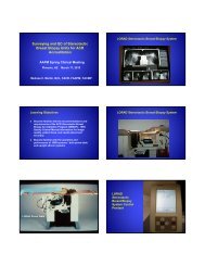
<strong>Proton</strong> <strong>Treatment</strong> <strong>Planning</strong><br />
Stefan Both<br />
University of Pennsylvania
OUTLINE<br />
<strong>Proton</strong> <strong>Treatment</strong> <strong>Planning</strong><br />
• <strong>Proton</strong> Technologies and <strong>Treatment</strong> Technique at UPenn<br />
• MLC Based Delivery and <strong>Treatment</strong> <strong>Planning</strong><br />
• Pencil Beam Scanning<br />
• Summary<br />
2
<strong>Proton</strong> Technologies and Techniques at UPenn<br />
Technologies:<br />
SS DS US PBS<br />
Techniques:<br />
SOBP SFUD IMPT<br />
3DCRT/IMRT IMRT<br />
3
<strong>Proton</strong> <strong>Treatment</strong> <strong>Planning</strong><br />
In PS, the integration of MLC allows for safer and more<br />
efficient automated processes.<br />
MLC redesigned based on the<br />
Varian MLC allows for:<br />
- Automated field shaping<br />
- Automated field matching<br />
patching (SOBP)<br />
- Automated delivery<br />
4
MLC Based Delivery and <strong>Treatment</strong> <strong>Planning</strong><br />
• Field Size: 22cm x 17cm<br />
• Neutron production<br />
“The neutron and combined proton plus gamma ray absorbed doses<br />
are nearly equivalent downstream from either a close tungsten alloy<br />
MLC or a solid brass block.”<br />
Diffenderfer et al. Med. Phys 11/2011; 38(11):6248-56<br />
• Penumbra characteristics:<br />
PDSMLC > PDSAP (~2mm)<br />
PUSMLC = PDSAP<br />
5
MLC Based Delivery and <strong>Treatment</strong> <strong>Planning</strong><br />
• MLC allows for automated field matching/patching based on<br />
volume segmentation techniques.<br />
• Facilitate the use of Half Beam Techniques.<br />
For example: Esophagus, Sarcoma.<br />
6
MLC Based Delivery and <strong>Treatment</strong> <strong>Planning</strong><br />
Esophagus<br />
7
MLC Based Delivery and <strong>Treatment</strong> <strong>Planning</strong><br />
Esophagus<br />
8
MLC Based Delivery and <strong>Treatment</strong> <strong>Planning</strong><br />
Sarcoma<br />
9
MLC Based Delivery and <strong>Treatment</strong> <strong>Planning</strong><br />
Sarcoma<br />
10
PBS Technology at UPenn<br />
• The Fix Beam Line Range (100 MEV to 235 MEV).<br />
• The Fix Beam Line Geometry allows for imaging at<br />
ISO & treatment AT &OFF ISO.<br />
• Targets
Spot size (mm)<br />
40<br />
35<br />
30<br />
25<br />
20<br />
15<br />
10<br />
5<br />
Spot Size<br />
100 120 140 160 180 200<br />
Beam Energy (MeV)<br />
X w/o RS<br />
X with RS<br />
Y w/o RS<br />
Y with RS
Spot Size Integrity<br />
• A Universal/Patient Specific Bolus was designed in order to be<br />
able to image and treat at the ISO while:<br />
- minimizing the air gap and the amount of material in the beam<br />
- maintain the size of the pencil beam<br />
13
Bolus Thickness
In TX Room Implementation<br />
15
Spot size (mm)<br />
35<br />
30<br />
25<br />
20<br />
15<br />
10<br />
5<br />
Spot Size (Bolus vs. Range Shifter)<br />
X direction<br />
No RS<br />
2cm Bolus<br />
8cm Bolus<br />
RS<br />
120 140 160 180 200<br />
Beam Energy (MeV)<br />
35<br />
30<br />
25<br />
20<br />
15<br />
10<br />
5<br />
Y direction<br />
No RS<br />
2cm Bolus<br />
8cm Bolus<br />
RS<br />
120 140 160 180 200<br />
Beam Energy (MeV)
The “Perfect” Clinical Example<br />
Base of Skull RT<br />
• Limited by proximity to the brainstem<br />
• Limited by proximity to optical structures<br />
• Limited by dose to the brain<br />
17
Bolus vs. Range Shifter
DVH comparison showing more uniform coverage and that the<br />
biggest differences in dose for the OARs are for the peripheral<br />
structures such as the cord and cochlea while the brainstem and<br />
chiasm are similar in the high dose region.
Prostate Motion and the Interplay Effect<br />
• PBS delivers a plan spots by spots; layers by layers.<br />
• Each Layer is delivered almost instantaneously.<br />
• The switch (beam energy tuning) between layers takes about<br />
10 seconds.<br />
• Prostate motion during beam energy tuning causes an<br />
interplay effect.
Considerations:<br />
Evaluating Interplay Effect<br />
• The lateral motion is negligible.*<br />
• AP and SI motions are significant.*<br />
• HUs of prostate and surrounding tissues are very close.<br />
• The prostate motion determined by the Calypso log file (0.5s).<br />
• The beam delivery log file determines the beam on and off time.<br />
• The dose to CTV is re-calculated by considering prostate drifting.<br />
*Wang, et. al. IJROBP, 11/2011
Motion in SI and AP for the Entire Course of<br />
<strong>Treatment</strong> (for One Patient)<br />
Best scenario<br />
Intermediate<br />
scenario<br />
Both, et. al. IJROBP, 12/2011<br />
Worst scenario
Prostate Drifting and Beam on Time<br />
Beam on time of Left Lateral Field Beam on time of Right Lateral Field
DVH of SFUD Plan
Prostate Drifting and Beam on Time<br />
Beam on time of Left Lateral Field Beam on time of Right Lateral Field
DVH of SFUD Plan
Interplay Effect on Dose Distribution
A-P Drift (mm)<br />
8<br />
7<br />
6<br />
5<br />
4<br />
3<br />
2<br />
The Worst Fraction<br />
During Right Lateral Beam Delivery During Left Lateral Beam Delivery<br />
11<br />
12<br />
8<br />
9<br />
10<br />
7<br />
6<br />
5<br />
3 4<br />
1<br />
1 2 3 4<br />
C-C Drift (mm)<br />
5 6 7<br />
2<br />
1<br />
A-P Drift (mm)<br />
8<br />
6<br />
4<br />
2<br />
10<br />
11<br />
12<br />
0 21<br />
4<br />
6 3<br />
7 5<br />
-2<br />
-2 0 2 4 6 8<br />
C-C Drift (mm)<br />
8<br />
9
DVH of IMPT Plan
Summary<br />
• Automated processes may improve proton therapy<br />
• MLC may be implemented for PBS and PS in TPS<br />
• PBS spot size may be preserved minimizing the air<br />
gap and the quantity of material in the beam<br />
• Motion effects may be addressed by quick delivery,<br />
rescanning, organ motion management, etc.
Acknowledgments<br />
Zelig Tochner<br />
Neha Vapiwala<br />
Paul James<br />
Maura Kirk<br />
Shikui Tang<br />
Christopher Ainsley<br />
Liyong Lin<br />
James McDonough<br />
Richard Maughan<br />
31
Thank you.<br />
32


![SBRT&StereoscopicIGRT_2012 [Compatibility Mode]](https://img.yumpu.com/16889220/1/184x260/sbrtstereoscopicigrt-2012-compatibility-mode.jpg?quality=85)