Nonlinear optical investigation of Gaussian laser beam propagating ...
Nonlinear optical investigation of Gaussian laser beam propagating ...
Nonlinear optical investigation of Gaussian laser beam propagating ...

You also want an ePaper? Increase the reach of your titles
YUMPU automatically turns print PDFs into web optimized ePapers that Google loves.
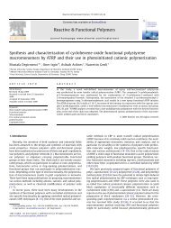
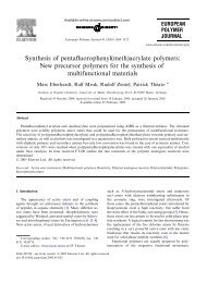
<strong>Nonlinear</strong> <strong>optical</strong> <strong>investigation</strong> <strong>of</strong> <strong>Gaussian</strong> <strong>laser</strong> <strong>beam</strong> <strong>propagating</strong> in a dye-doped<br />
nematic liquid crystal<br />
S.H. Mousavi a,d, ⁎, E. Koushki b,c , H. Haratizadeh a<br />
a Physics Department, Shahrood University <strong>of</strong> Technology, Shahrood, Iran<br />
b Photonic Laboratory, Physics Department, Tarbiat Moallem University, Tehran, Iran<br />
c Physics Department, Tarbiat Moallem University <strong>of</strong> Sabzevar, Sabzevar, Iran<br />
d Physics Department, Semnan University Semnan, Iran<br />
article info<br />
Article history:<br />
Received 13 September 2009<br />
Received in revised form 22 January 2010<br />
Accepted 25 January 2010<br />
Available online 1 February 2010<br />
Keywords:<br />
Curvature radius<br />
Beam radius<br />
<strong>Nonlinear</strong> <strong>optical</strong> material<br />
Liquid crystal<br />
1. Introduction<br />
abstract<br />
Liquid crystals are mesophases between crystalline solids and<br />
isotropic liquids. Recently, the nonlinear effects <strong>of</strong> azo-dye-doped<br />
liquid crystals (ADDLCs), such as photorefractive effect [1–3] and<br />
degenerate four-wave mixing [4], have attracted much interest due to<br />
their applications in <strong>optical</strong> devices such as liquid crystal displays<br />
which are used in electronic watches, calculators, laptop and desktop<br />
computers.<br />
In linear <strong>optical</strong> processes the physical properties <strong>of</strong> the liquid<br />
crystal, such as molecular structure, individual or collective molecular<br />
orientation, temperature, density, and population <strong>of</strong> electronic levels<br />
are not affected by the <strong>optical</strong> fields. However the direction,<br />
amplitude, intensity, and phase <strong>of</strong> the <strong>optical</strong> fields are affected in a<br />
unidirectional way. Liquid crystals are <strong>optical</strong>ly highly nonlinear<br />
materials and their physical properties i.e. temperature, molecular<br />
orientation, density and electronic structure can be easily perturbed<br />
by applied <strong>optical</strong> field [5–9]. Since liquid crystalline molecules are<br />
anisotropic hence a polarized light from a <strong>laser</strong> source can induce an<br />
alignment or order in the isotropic phase, or realign the molecules in<br />
the ordered phase.<br />
⁎ Corresponding author. Physics Department, Shahrood University <strong>of</strong> Technology,<br />
Shahrood 3619995161, Iran. Tel.: +98 912 1909450; fax: +98 273 3335270.<br />
E-mail addresses: hadi_mousavi@yahoo.com, mousavi@phys.tus.ac.ir<br />
(S.H. Mousavi).<br />
0167-7322/$ – see front matter © 2010 Elsevier B.V. All rights reserved.<br />
doi:10.1016/j.molliq.2010.01.008<br />
Journal <strong>of</strong> Molecular Liquids 153 (2010) 124–128<br />
Contents lists available at ScienceDirect<br />
Journal <strong>of</strong> Molecular Liquids<br />
journal homepage: www.elsevier.com/locate/molliq<br />
The <strong>laser</strong> <strong>beam</strong> shape and variation <strong>of</strong> the curvature radius <strong>of</strong> the wavefront have been simulated when the<br />
<strong>Gaussian</strong> <strong>laser</strong> <strong>beam</strong> passes through a dye-doped nematics liquid crystal. The effect <strong>of</strong> different dyes is<br />
investigated in the wavefront distortion as well as the <strong>beam</strong> shape due to its quality factor. We have reported<br />
the dependency <strong>of</strong> the curvature radius <strong>of</strong> the wavefront to the nonlinearity <strong>of</strong> the sample. Also we have<br />
obtained the <strong>beam</strong> shape <strong>of</strong> three dyes doped nematic liquid crystal as a nonlinear <strong>optical</strong> material compared<br />
with the experimental results.<br />
© 2010 Elsevier B.V. All rights reserved.<br />
The <strong>optical</strong> properties <strong>of</strong> liquid crystals can be controlled by<br />
external applied DC or low-frequency fields; which gives rise to a<br />
variety <strong>of</strong> electro-<strong>optical</strong> effects which are widely used in many<br />
electro-<strong>optical</strong> display and image-processing applications.<br />
There are several methods for nonlinear characterization <strong>of</strong><br />
materials such as z-scan which is a powerful technique to obtain both<br />
the sign and magnitude <strong>of</strong> the complex nonlinear refractive index <strong>of</strong><br />
some <strong>optical</strong> materials. This technique is based on the principle that<br />
spatial variations <strong>of</strong> the incident intensity distribution can photoinduce<br />
a lens in the nonlinear material which affects the posterior propagation<br />
<strong>of</strong> the <strong>beam</strong> and intensity changes at the far-field.<br />
During developing the z-scan technique [10,11], manyimprovements<br />
and modifications have been suggested due to its sensitivity and<br />
simplicity such as eclipsing [12],tophat<strong>beam</strong>s[13], two colours [14] and<br />
reflection [15]. Detailed analysis <strong>of</strong> the parameters affecting the z-scan<br />
measurements was reported by Chapple et al. [16]. In this <strong>investigation</strong>, a<br />
<strong>Gaussian</strong> <strong>beam</strong> incident to a thin Kerr nonlinear sample was considered<br />
to obtain simple analytical formulas relating the z-scan curve obtained<br />
from the on-axis intensity at the far-field. <strong>Gaussian</strong> decomposition<br />
method has been used to analyze the characteristics <strong>of</strong> the z-scan curves<br />
for thin samples with small or large nonlinear phase shifts.<br />
In this paper, we focus on nonlinear properties <strong>of</strong> dye-doped liquid<br />
crystal. Also, we have studied the <strong>laser</strong> <strong>beam</strong> propagation in a thin<br />
nonlinear material (dye-doped liquid crystal) and compared with<br />
experimental data. Furthermore, the radius <strong>of</strong> curvature <strong>of</strong> the<br />
wavefront was calculated and it is found that convergent (divergent)<br />
<strong>Gaussian</strong> <strong>beam</strong> passing through a self-focusing sample, the radius <strong>of</strong><br />
curvature <strong>of</strong> the wavefront becomes larger (smaller).
2. Theoretical approach<br />
A plane wave and a spherical wave represent two opposite<br />
extremes <strong>of</strong> angular and spatial confinement. Waves including<br />
wavefront normals which make small angles with the z-axis are<br />
called paraxial waves and they must satisfy the paraxial Helmholtz<br />
equation [17].<br />
An important solution <strong>of</strong> the mentioned equation which exhibits<br />
the characteristics <strong>of</strong> an <strong>optical</strong> <strong>beam</strong> is a wave called the <strong>Gaussian</strong><br />
<strong>beam</strong>. The electric field <strong>of</strong> a TEM00 <strong>Gaussian</strong> <strong>beam</strong> with <strong>beam</strong> waist<br />
radius w0 travelling in the z direction can be written as<br />
W 0<br />
Einðr; zÞ<br />
= A0 Wz ðÞ<br />
Wz ðÞ= W0 1+ z<br />
z0 Rz ðÞ= z 1+ z0 z<br />
ρ2<br />
exp −<br />
W2 !<br />
ðÞ z<br />
2<br />
2 1= 2<br />
exp −ikz−ik ρ2<br />
+ iζ z<br />
2RðÞ z<br />
ðÞ<br />
!<br />
where I 0, W(z), R(z) and z 0 are respectively the irradiance at <strong>beam</strong><br />
waist <strong>of</strong> the <strong>Gaussian</strong> <strong>beam</strong>, the <strong>beam</strong> radius at z, the radius <strong>of</strong><br />
curvature <strong>of</strong> the wavefront at z and the diffraction length <strong>of</strong> the <strong>beam</strong><br />
respectively and ζðÞ= z tan −1 z<br />
z ;W0 =<br />
0<br />
λz0 π<br />
1 = 2<br />
.<br />
In this study, first <strong>of</strong> all some <strong>of</strong> <strong>Gaussian</strong> <strong>beam</strong> parameters such<br />
as intensity, <strong>beam</strong> radius and curvature radius are introduced.<br />
Within any transverse plane, the <strong>beam</strong> intensity assumes its peak<br />
value on the <strong>beam</strong> axis, and drops by the factor l/e 2 at the radial<br />
distance ρ=W(z). Since 86% <strong>of</strong> the power is carried within a circle <strong>of</strong><br />
radius W(z), we regard W(z) as the <strong>beam</strong> radius. The phase <strong>of</strong> the<br />
<strong>Gaussian</strong> <strong>beam</strong> could be calculated from Eq. (1). It is given by<br />
φρ;z ð Þ = kz−ζðÞ+ z<br />
kρ2<br />
: ð4Þ<br />
2RðÞ z<br />
On the <strong>beam</strong> axis (ρ=0) the phase<br />
φρ;z ð Þ = kz−ζðÞ: z<br />
ð5Þ<br />
The first term <strong>of</strong> Eq. (4), kz, is the phase <strong>of</strong> a plane wave and the<br />
second represents a phase retardation E(z) given which ranges from<br />
−π/2atz=−∞ to +π/2atz=∞. This phase retardation corresponds<br />
to an excess delay <strong>of</strong> the wavefront in comparison with a plane wave<br />
or a spherical wave. The total accumulated excess retardation as the<br />
wave travels from z=−∞ to z=∞ is π. The last term is responsible for<br />
wavefront bending. It represents the deviation <strong>of</strong> the phase at <strong>of</strong>f-axis<br />
points in a given transverse plane from that at the axial point. Because<br />
the variations <strong>of</strong> tan −1 (z/z0) and R(z) are slow, the constant phase<br />
surfaces satisfy the following equation:<br />
z +<br />
2<br />
r<br />
2RðÞ z<br />
ζ z<br />
= m + ðÞ<br />
2π<br />
ð1Þ<br />
ð2Þ<br />
ð3Þ<br />
× λ≈constant: ð6Þ<br />
This is the equation <strong>of</strong> a paraboloidal surface <strong>of</strong> curvature radius<br />
R;whereR(z) is the radius <strong>of</strong> curvature <strong>of</strong> the wavefront at position z<br />
on the <strong>beam</strong> axis. The radius <strong>of</strong> curvature R(z) isinfinite at z =0,<br />
corresponding to plane wavefronts. It decreases to a minimum value<br />
<strong>of</strong> 2z0 at z = z0. The radius <strong>of</strong> curvature subsequently increases with<br />
further increase <strong>of</strong> z until R(z)=z for z ≫ z 0. The wavefront is then<br />
approximately the same as that <strong>of</strong> a spherical wave. For negative z<br />
the wavefronts follow an identical pattern, except for a change in<br />
sign.<br />
S.H. Mousavi et al. / Journal <strong>of</strong> Molecular Liquids 153 (2010) 124–128<br />
If the <strong>Gaussian</strong> <strong>beam</strong> passes through a thin third-order nonlinear<br />
<strong>optical</strong> sample with nonlinear refraction c (MKS) located at z, the<br />
phase shift <strong>of</strong> the <strong>Gaussian</strong> <strong>beam</strong> is given by:<br />
Δφ0 Δφ0ðz;rÞ =<br />
1+ z<br />
z 0<br />
2<br />
2 r<br />
2<br />
e−w 2 ðÞ z<br />
ð7Þ<br />
where Δφ0=kγI0Leff=kΔnI0 and Leff = 1−e−αL ð Þ .<br />
. The electric field<br />
α<br />
at the exit plane <strong>of</strong> the sample is obtained [10], and the far-field at a<br />
vertical plane in the far-field is given by:<br />
Er;z ð Þ = Ein z;r<br />
ð Þe −αL= ∞<br />
2 ∑<br />
m =0<br />
½iΔφ0ðÞ z Š m<br />
wm0 exp −<br />
m! wm r 2<br />
w 2 m<br />
− ikr2<br />
!<br />
+ iθ m<br />
2R m<br />
where the term E in(r=0, z) is the input electric field <strong>of</strong> the incident<br />
<strong>Gaussian</strong> <strong>beam</strong> at the sample plane. Defining d as the propagation<br />
distance in free space from the sample to the plane <strong>of</strong> the far-field and<br />
g=1+d/R(z), the remaining parameters in Eq. (8) are expressed as:<br />
w 2<br />
m 0 = w 2 ðÞ z<br />
2m +1<br />
dm = kw2 m 0<br />
2<br />
w 2 2<br />
m = wm 0 g 2 + d2<br />
d2 " #<br />
m<br />
R m = d½1−<br />
g<br />
g 2 2<br />
d<br />
+<br />
θm = tan −1 d " #<br />
dm<br />
g<br />
:<br />
d 2<br />
−1<br />
mŠ<br />
The electric field <strong>of</strong> the <strong>beam</strong> is now a summation <strong>of</strong> some<br />
sub<strong>beam</strong>s having individually own wavefront curvature radius at<br />
position z. The parameter W(z) guides us to stimulate the <strong>beam</strong> pr<strong>of</strong>ile<br />
before and after transmitting the <strong>beam</strong> from the sample.<br />
3. Discussion and experimental approach<br />
We used three azo-dyes (Sudan black b, Sudan III and Sudan IV)<br />
doped to a nematic liquid crystal (w1680) which their nonlinear<br />
<strong>optical</strong> properties have been investigated in recent works [18,19].<br />
Sudan dyes were obtained from Merck and used as the guest. A<br />
nematic mixture <strong>of</strong> w1680 was synthesized in the Institute <strong>of</strong><br />
Chemistry <strong>of</strong> the Military Technical Academy, Warsaw, Poland, and<br />
used as the host. The dyes are dissolved in a nematic liquid crystal<br />
with 1% concentration. The guest–host cell was made by sandwiching<br />
the solutions between two <strong>optical</strong> glass plates (2×1.2 cm 2 ). The<br />
homeotropic orientation <strong>of</strong> the guest and host molecules was<br />
achieved by depositing <strong>of</strong> a thin layer <strong>of</strong> lecithin on the clean glass<br />
surfaces and mylar film (12.5 μm) was used as the spacer. The plates<br />
were sealed together by epoxy resin glue. The liquid crystal cells were<br />
Table 1<br />
<strong>Nonlinear</strong> parameters <strong>of</strong> samples.<br />
Doped material Laser intensity I 0<br />
(W/cm 2 )<br />
Rayleigh range<br />
(cm)<br />
n 2<br />
(cm 2 /W)<br />
Sudan black b 641 0.31 1.01 ×10 −6<br />
Sudan III 794 3.12 2.1×10 −6<br />
Sudan IV 1440 3.12 8.04 ×10 −6<br />
125<br />
ð8Þ<br />
ð9Þ
126 S.H. Mousavi et al. / Journal <strong>of</strong> Molecular Liquids 153 (2010) 124–128<br />
Fig. 1. Curvature radius <strong>of</strong> wavefront as function <strong>of</strong> z when nematic liquid crystal doped<br />
with Sudan black b (solid line for sample at z=z 0=0.31 cm and Δφ 0=6.3×10 −3 ).<br />
checked under crossed polarizers and used in subsequent <strong>optical</strong><br />
studies.<br />
The nonlinear refraction indices have been measured using z-scan<br />
and moiré deflectometry methods. The results show positive<br />
nonlinear refractive indices being in order <strong>of</strong> 10 −6 or 10 −7 cm 2 /W<br />
for the corresponding dyes doped nematic liquid crystal, demonstrating<br />
self-focusing <strong>optical</strong> nonlinearity. These values are summarized<br />
in Table 1.<br />
From the standpoint <strong>of</strong> <strong>optical</strong> properties, the doping <strong>of</strong> liquid<br />
crystals by appropriately dissolved concentrations and types <strong>of</strong> dyes<br />
clearly deserves special attention. The most important effect <strong>of</strong> dye<br />
molecules on liquid crystals is the modification <strong>of</strong> their nonlinear<br />
<strong>optical</strong> properties. These molecules are generally elongated in shape<br />
and can be oriented and reoriented by the host nematic liquid crystals.<br />
Light propagation through a medium depends on whether the<br />
light–matter interaction is linear or nonlinear. In linear optics, the<br />
light fields are not intense enough to create appreciable changes in the<br />
<strong>optical</strong> properties <strong>of</strong> the medium (e.g., refractive index, absorption or<br />
scattering cross sections) and so its propagation through the medium<br />
is therefore dictated primarily by its properties. In nonlinear optics,<br />
the light–matter interactions are sufficiently intense so that the<br />
<strong>optical</strong> properties <strong>of</strong> the medium are affected by the <strong>optical</strong> fields. For<br />
example, the <strong>optical</strong> field is intense enough to cause director axis<br />
reorientations. Such interactions give rise to many so-called selfaction<br />
effects such as self-focusing.<br />
Fig. 2. Curvature radius <strong>of</strong> wavefront as function <strong>of</strong> z when nematic liquid crystal doped<br />
with Sudan III (solid line for sample at z=z 0=3.1 cm and Δφ 0=2.4×10 −3 ).<br />
Fig. 3. Curvature radius <strong>of</strong> wavefront as function <strong>of</strong> z when nematic liquid crystal doped<br />
with Sudan IV (solid line for sample at z=z0=3.1 cm and Δφ0=2.1 ×10 −3 ).<br />
The experiments for pure nematic crystal indicate that these dyes<br />
can enhance the <strong>optical</strong> nonlinearity. It can be inferred that the n2 for<br />
dye-doped liquid crystal is about two orders <strong>of</strong> magnitude greater<br />
than that for pure liquid crystals.<br />
In order to obtain the maximum deformation <strong>of</strong> <strong>laser</strong> <strong>beam</strong> we<br />
put the sample at z0. Using our numerical method we revealed that<br />
the transmitted <strong>beam</strong> is yet a <strong>Gaussian</strong> <strong>beam</strong>, it is expected that the<br />
shape <strong>of</strong> the wavefronts remains a paraboloidal surface and Eq. (6) is<br />
valid. In order to find the radius <strong>of</strong> the curvature <strong>of</strong> the wavefront at<br />
position z, the phase magnitude <strong>of</strong> the <strong>beam</strong> on the propagation axis<br />
at z was calculated. Figs. 1–3 show the radii <strong>of</strong> curvature <strong>of</strong> the<br />
wavefront as function <strong>of</strong> z for Sudan black b, Sudan III and Sudan IV<br />
respectively (assuming the sample is placed near z 0). The curves show<br />
that in small values <strong>of</strong> z (near z=0) the curvature radius is very large<br />
while R(z)≈z for z≫z 0 region which is in good agreement with<br />
Eq. (3). Also for different values <strong>of</strong> nonlinear refractions, the slopes <strong>of</strong><br />
lines are unique and don't depend on the position or quality <strong>of</strong> the<br />
sample (the position <strong>of</strong> the sample only affects the magnitude <strong>of</strong> the<br />
refractive nonlinearity according to Eq. (7)). The changes in refractive<br />
nonlinearity cause small shifts <strong>of</strong> lines in vertical direction while the<br />
slope remains constant. The maximum <strong>beam</strong> distortion from the<br />
original one appears in Sudan black b which has the greater<br />
Fig. 4. Laser <strong>beam</strong> shape (a) without sample and (b) with sample “Sudan black b”<br />
placed at z 0. (c) with sample by applying 0.5 (V) ac voltage. Squares and dots are<br />
experimental data for v=0 and v=0.5 (V) respectively.
Fig. 5. Laser <strong>beam</strong> shape (a) without sample and (b) with sample “Sudan III” placed at<br />
z 0. (c) with sample by applying 0.5 (V) ac voltage. Squares and dots are experimental<br />
data for v=0 and v=0.5 (V) respectively.<br />
nonlinearity properties and larger values <strong>of</strong> Δφ 0 while for Sudan IV<br />
the minimum distortion is observed because the curves in Fig. 3 tend<br />
to each other. These results revealed that the doping <strong>of</strong> liquid crystals<br />
by appropriately dissolved concentrations and types <strong>of</strong> dyes clearly<br />
deserves special attention. The most important effect <strong>of</strong> dye molecules<br />
on liquid crystals is modification <strong>of</strong> their nonlinear and <strong>optical</strong><br />
properties. These molecules are generally elongated in shape and can<br />
be oriented and reoriented by the host nematic liquid crystals.<br />
In the other simulation, we investigated the <strong>beam</strong> shape<br />
<strong>propagating</strong> through the mentioned samples. So that, the sample<br />
was put at a fixed point (z=z 0). The <strong>beam</strong> radius can be obtained by<br />
Eq. (8) at a far vertical plane located at z. This plane has been moved to<br />
the sample place in finite negligible stages and calculations were done<br />
for each stage. A series <strong>of</strong> continuous <strong>beam</strong> radii has been obtained<br />
and the asymptotic curve is the <strong>beam</strong> pr<strong>of</strong>ile. Experimentally the<br />
<strong>beam</strong> pr<strong>of</strong>iles are obtained by the edge-scan technique which can be<br />
compared with solid line in Figs. 4–6. InFig. 4, the dashed line is a<br />
Fig. 6. Laser <strong>beam</strong> shape (a) without sample and (b) with sample “Sudan IV” placed at<br />
z 0. (c) with sample by applying 0.5 (V) ac voltage (very similar to ideal <strong>Gaussian</strong> <strong>beam</strong><br />
shape). Squares and dots are experimental data for v=0 and v=0.5 (V) respectively.<br />
S.H. Mousavi et al. / Journal <strong>of</strong> Molecular Liquids 153 (2010) 124–128<br />
Table 2<br />
Δφ 0 and M 2 -factor <strong>of</strong> samples.<br />
Doped<br />
material<br />
theoretical curve when Sudan black b is placed at z=z 0. The squares<br />
are experimental data which are in good agreement with the<br />
theoretical curve. Also they are compared with the <strong>beam</strong> shape in<br />
the case that the sample does not exist. The <strong>beam</strong> shape before the<br />
sample is obtained from simple paraxial approximation. The results<br />
are compared with the condition that voltage is used. Using 0.5 (V) ac<br />
voltage, the nonlinearity decreases and the theoretical curve (solid<br />
line in Fig. 4) tends to the <strong>Gaussian</strong> <strong>beam</strong> shape. Also this curve is in<br />
good agreement with experimental data (dot points). Applied voltage<br />
in the direction <strong>of</strong> the NLC director on a homeotropic-aligned cell can<br />
affect both τ → em and τ → dye. The former is because <strong>of</strong> the fact that the<br />
induced polarization <strong>of</strong> the NLC molecules under interaction with the<br />
external field will fix at the initial alignment direction. By increasing<br />
the applied voltage, the voltage-induced torque finally overcomes the<br />
light-induced torque and the light-induced reorientation effect,<br />
consequently τ → em, will disappear. Therefore, by increasing the applied<br />
voltage the dye molecules can be aligned in the direction <strong>of</strong> the<br />
external field. In this case, all the dye molecules situated around the<br />
host NLC molecules will have the same excitation probabilities, hence<br />
→<br />
τ dye disappears due to this process so the nonlinearity decreases.<br />
Fig. 4 and Fig. 5 show these analyses for Sudan III and Sudan IV<br />
respectively.<br />
For Sudan IV with the smallest nonlinearity the curves are very<br />
similar with the case that the sample does not exist. The deviation from<br />
an ideal <strong>Gaussian</strong> <strong>beam</strong> shape is expressed by M 2 -factor parameter, this<br />
deviation is defined as the distortion <strong>of</strong> the <strong>Gaussian</strong> shape causes<br />
changes in the angle between the <strong>beam</strong> shape and the z-axes<br />
[20]. Table 2 shows the obtained values for Δφ0 and M 2 -factor.<br />
4. Conclusion<br />
The nonlinear properties <strong>of</strong> the <strong>Gaussian</strong> <strong>laser</strong> <strong>beam</strong> have been<br />
investigated for three different azo-dyes. A theoretical method to<br />
calculate the curvature radius <strong>of</strong> the wavefront <strong>of</strong> a <strong>Gaussian</strong> <strong>beam</strong><br />
passing through different dye-doped nematic liquid crystals is<br />
expressed. Also the effect <strong>of</strong> the nonlinearity on the <strong>laser</strong> <strong>beam</strong><br />
shape and deviation from ideal the <strong>beam</strong> pr<strong>of</strong>ile are calculated and<br />
compared with experimental data. The results show larger nonlinearity<br />
decreases curvature radius and distortion from the ideal<br />
<strong>Gaussian</strong> <strong>beam</strong> shape.<br />
References<br />
Δφ0 without<br />
voltage<br />
Sudan black b 6.3 ×10 −3<br />
Sudan III 2.4 ×10 −3<br />
Sudan IV 2.1 ×10 −3<br />
M 2 -factor<br />
without<br />
voltage<br />
Δφ0 by applying<br />
0.5 (V) ac voltage<br />
0.9 2.2×10 −3<br />
0.93 1.0×10 −3<br />
0.95 0.8×10 −4<br />
M 2 -factor by<br />
applying 0.5 (V)<br />
ac voltage<br />
0.95<br />
0.975<br />
0.99<br />
[1] I.C. Khoo, H. Li, Y. Liang, Opt. Lett. 19 (1994) 1723.<br />
[2] I.C. Khoo, IEEE J. Quantum Electron. 32 (1996) 525.<br />
[3] M.-R. Lee, J.-R. Wang, C.-R. Lee, A.Y.-G. Fuh, Appl. Phys. Lett. 85 (2004) 5822.<br />
[4] I.V. Tomov, T.E. Dutton, B. VanWonterghem, P.M. Rentzepis, J. Appl. Phys. 70<br />
(1991) 36.<br />
[5] I.C. Khoo, Phys. Rev. A. 23 (1981) 2077.<br />
[6] S.D. Durbin, S.M. Arakelian, Y.R. Shen, Phys. Rev. Lett. 47 (1981) 1411.<br />
[7] R.M. Herman, R.J. Serinko, Phys. Rev. A. 19 (1979) 1757.<br />
[8] I.C. Khoo, R.G. Lindquist, R.R. Michael, R.J. Mansfield, P.G. LoPresti, J. Appl. Phys. 69<br />
(1991) 3853.<br />
[9] N.V. Tabiryan, B.Ya. Zeldovich, Mol. Cryst. Liq. Cryst. 62 (1980) 237.<br />
[10] M. Sheik Bahae, A.A. Said, E.W. Van Stryland, Opt. Lett. 14 (1989) 955.<br />
[11] M. Sheik-Bahae, A.A. Said, T. Wei, D. Hagan, E.W. Van Stryland, IEEE J. Quantum<br />
Electron. 26 (1990) 760.<br />
[12] T. Xia, D.J. Hagan, M. Sheik-Bahae, E.W. Van Stryland, Opt. Lett. 19 (1994) 317.<br />
[13] W. Zhao, P. Palffy-Muhoray, Appl. Phys. Lett. 63 (1993) 1613.<br />
[14] H. Ma, A.S.L. Gomes, C.B. de Araujo, Appl. Phys. Lett. 59 (1991) 2666.<br />
127
128 S.H. Mousavi et al. / Journal <strong>of</strong> Molecular Liquids 153 (2010) 124–128<br />
[15] D.V. Petrov, A.S.L. Gomes, C.B. de Araujo, Appl. Phys. Lett. 65 (1994) 1067.<br />
[16] P.B. Chapple, J. Staromlynska, J.A. Hermann, T.J. Mckay, R.G. McDuff, J. <strong>Nonlinear</strong><br />
Opt. Phys. 6 (1997) 251.<br />
[17] B.E.A. Saleh, M.C. Teich, Fundamentals <strong>of</strong> Photonics, First editionWiley, New York,<br />
1991.<br />
[18] M.H. Majles Ara, S.H. Mousavi, S. Salmani, E. Koushki, J. Mol. Liq. 140 (2008) 21.<br />
[19] M.H. Majles Ara, S.H. Mousavi, E. Koushki, S. Salmani, A. Gharibi, A. Ghanadzadeh,<br />
J. Mol. Liq. 142 (2008) 29.<br />
[20] E. Koushki, S.H. Mousavi, M.H. Majles Ara, A. Koushki, Curr. Appl. Phys. 9 (2009) 1347.