Lab #4: Designing a 4-bit Incrementer & A 4-bit Adder
Lab #4: Designing a 4-bit Incrementer & A 4-bit Adder
Lab #4: Designing a 4-bit Incrementer & A 4-bit Adder
Create successful ePaper yourself
Turn your PDF publications into a flip-book with our unique Google optimized e-Paper software.
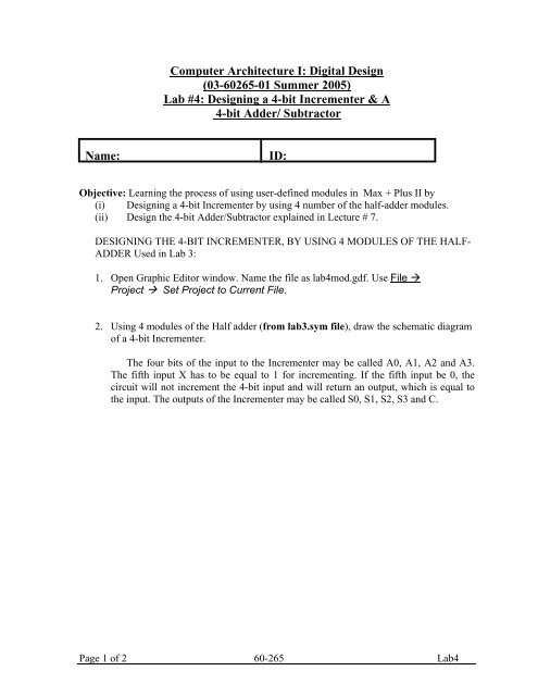
Computer Architecture I: Digital Design<br />
(03-60265-01 Summer 2005)<br />
<strong>Lab</strong> <strong>#4</strong>: <strong>Designing</strong> a 4-<strong>bit</strong> <strong>Incrementer</strong> & A<br />
4-<strong>bit</strong> <strong>Adder</strong>/ Subtractor<br />
Name: ID:<br />
Objective: Learning the process of using user-defined modules in Max + Plus II by<br />
(i) <strong>Designing</strong> a 4-<strong>bit</strong> <strong>Incrementer</strong> by using 4 number of the half-adder modules.<br />
(ii) Design the 4-<strong>bit</strong> <strong>Adder</strong>/Subtractor explained in Lecture # 7.<br />
DESIGNING THE 4-BIT INCREMENTER, BY USING 4 MODULES OF THE HALF-<br />
ADDER Used in <strong>Lab</strong> 3:<br />
1. Open Graphic Editor window. Name the file as lab4mod.gdf. Use File <br />
Project Set Project to Current File.<br />
2. Using 4 modules of the Half adder (from lab3.sym file), draw the schematic diagram<br />
of a 4-<strong>bit</strong> <strong>Incrementer</strong>.<br />
The four <strong>bit</strong>s of the input to the <strong>Incrementer</strong> may be called A0, A1, A2 and A3.<br />
The fifth input X has to be equal to 1 for incrementing. If the fifth input be 0, the<br />
circuit will not increment the 4-<strong>bit</strong> input and will return an output, which is equal to<br />
the input. The outputs of the <strong>Incrementer</strong> may be called S0, S1, S2, S3 and C.<br />
Page 1 of 2 60-265 <strong>Lab</strong>4
3. Express the outputs as functions of the inputs.<br />
S0 =<br />
S1 =<br />
S2 =<br />
S3 =<br />
C =<br />
4. Verify your design of (2) using a simulator. (The X input of the <strong>Incrementer</strong><br />
is a constant at 1.) Note: For 4 inputs, an end-time of 100.0 ns with a grid size of 5.0 ns<br />
may be chosen.<br />
5. Obtain the “truth table” for the <strong>Incrementer</strong>.<br />
6. Design the full <strong>Adder</strong>/ Subtractor circuit explained in lecture #7 .<br />
Verify your results with the GA/TA.<br />
Page 2 of 2 60-265 <strong>Lab</strong>4


