ul test report and procedure - Zippy Switch Tech. Corp.
ul test report and procedure - Zippy Switch Tech. Corp.
ul test report and procedure - Zippy Switch Tech. Corp.

Create successful ePaper yourself
Turn your PDF publications into a flip-book with our unique Google optimized e-Paper software.
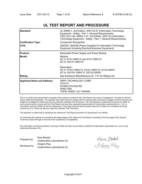
Issue Date: 2011-05-13 Page 1 of 22 Report Reference # E143756-A100-UL<br />
UL TEST REPORT AND PROCEDURE<br />
St<strong>and</strong>ard: UL 60950-1, 2nd Edition, 2007-03-27 (Information <strong>Tech</strong>nology<br />
Equipment - Safety - Part 1: General Requirements)<br />
CSA C22.2 No. 60950-1-07, 2nd Edition, 2007-03 (Information<br />
<strong>Tech</strong>nology Equipment - Safety - Part 1: General Requirements)<br />
Certification Type: Component Recognition<br />
CCN: QQGQ2, QQGQ8 (Power Supplies for Information <strong>Tech</strong>nology<br />
Equipment Including Electrical Business Equipment)<br />
Product: Redundant Power Supply <strong>and</strong> Power Mod<strong>ul</strong>e<br />
Model: Mod<strong>ul</strong>e:<br />
AC in: R1X-1060V12 <strong>and</strong> G1X-1060V12<br />
DC in: DG1X-1060V12<br />
Redundant:<br />
AC in: R1X2-1060V12, G1X2-1060V12, G1X2-5060V<br />
DC in: DG1X2-1060V12, DG1X2-5060V<br />
Rating: See Enclosure Miscellaneous ID. 7-01 for Rating List<br />
Applicant Name <strong>and</strong> Address: ZIPPY TECHNOLOGY CORP<br />
10TH FL<br />
50 MIN CHYUAN RD<br />
SHIN-TIEN<br />
TAIPEI HSIEN 231 TAIWAN<br />
This is to certify that representative samples of the products covered by this Test Report have been investigated in accordance with the<br />
above referenced St<strong>and</strong>ards. The products have been found to comply with the requirements covering the category <strong>and</strong> the products are<br />
judged to be eligible for Follow-Up Service under the indicated Test Procedure. The manufacturer is authorized to use the UL Mark on<br />
such products which comply with this Test Report <strong>and</strong> any other applicable requirements of Underwriters Laboratories Inc. ('UL') in<br />
accordance with the Follow-Up Service Agreement. Only those products which properly bear the UL Mark are considered as being<br />
covered by UL's Follow-Up Service under the indicated Test Procedure.<br />
The applicant is authorized to reproduce the referenced Test Report provided it is reproduced in its entirety.<br />
UL authorizes the applicant to reproduce the la<strong>test</strong> pages of the referenced Test Report consisting of the first page of the Specific<br />
<strong>Tech</strong>nical Criteria through to the end of the Conditions of Acceptability.<br />
Any information <strong>and</strong> documentation involving UL Mark services are provided on behalf of Underwriters Laboratories Inc. (UL) or any<br />
authorized licensee of UL.<br />
Prepared by:<br />
Reviewed by:<br />
Kara Bostad<br />
Underwriters Laboratories Inc.<br />
Gregory Ray<br />
Underwriters Laboratories Inc.<br />
Copyright © 2011
Issue Date: 2011-05-13 Page 2 of 22 Report Reference # E143756-A100-UL<br />
Supporting Documentation<br />
The following documents located at the beginning of this Procedure supplement the requirements of this Test<br />
Report:<br />
A. Authorization - The Authorization page may include additional Factory Identification Code markings.<br />
B. Generic Inspection Instructions -<br />
i. Part AC details important information which may be applicable to products covered by this Procedure.<br />
Products described in this Test Report must comply with any applicable items listed unless otherwise<br />
stated in the body of this Test Report.<br />
ii. Part AE details any requirements which may be applicable to all products covered by this Procedure.<br />
Products described in this Test Report must comply with any applicable items listed unless otherwise<br />
stated in the body of each Test Report.<br />
iii. Part AF details the requirements for the UL Certification Mark which is not controlled by the technical<br />
st<strong>and</strong>ard used to investigate these products. Products are permitted to bear only the Certification<br />
Mark(s) corresponding to the countries for which it is certified, as indicated in each Test Report.<br />
Product Description<br />
The Redundant Power Supply, Models R1X2-1060V12, G1X2-1060V12 <strong>and</strong> G1X2-5060V are a 1+1 hotswappable<br />
AC to DC Power Supply for use in Information <strong>Tech</strong>nology Equipment (ITE).<br />
The Redundant Power Supply, Models DG1X2-1060V12 <strong>and</strong> DG1X2-5060V are a 1+1 hot-swappable DC to<br />
DC Power Supply for use in Information <strong>Tech</strong>nology Equipment (ITE).<br />
The Power Supply Mod<strong>ul</strong>e is power supply board <strong>and</strong> housed in metal chassis.<br />
All Redundant Power Supply models are composed of 2 power mod<strong>ul</strong>es maximum.<br />
Model Differences<br />
Models R1X-1060V12, G1X-1060V12, DG1X-1060V12 are Power Mod<strong>ul</strong>es.<br />
Model R1X-1060V12, G1X-1060V12 is similar to Model DG1X-1060V12, except input voltage, primary<br />
circuit, <strong>and</strong> transformer.<br />
Models R1X2-1060V12, G1X2-1060V12, G1X2-5060V, DG1X2-1060V12, DG1X2-5060V are Redundant<br />
Power Supply.<br />
Model R1X2-1060V12, G1X2-1060V12 is similar to Model G1X2-5060V, except output rating.<br />
Model DG1X2-1060V12 is similar to Model DG1X2-5060V, except output rating.<br />
Model DG1X2-5060V is similar to Model G1X2-5060V, except input <strong>and</strong> output rating.<br />
Model nomenclature for Mod<strong>ul</strong>e:<br />
- R1X-"1" denotes 1 output;<br />
- R1X-1060V”12” denotes only 12V output;<br />
- DG1X-1060V12, "D" denotes DC main supply;<br />
Model nomenclature for Redundant Power Supply:<br />
- R1X"2" denotes 2 Mod<strong>ul</strong>es type chassis;<br />
- R1X2-"1" denotes 1 outputs;<br />
- R1X2-1060V”12” denotes only 12V output;<br />
- G1X2-“5” denotes 5 outputs;<br />
<strong>Tech</strong>nical Considerations<br />
Equipment mobility : for building-in<br />
Connection to the mains : pluggable A (For Models R1X <strong>and</strong> G1X series); permanent connection
Issue Date: 2011-05-13 Page 3 of 22 Report Reference # E143756-A100-UL<br />
(DC Mains) (For Models DG1X series)<br />
Operating condition : continuous<br />
Access location : operator accessible<br />
Over voltage category (OVC) : OVC II<br />
Mains supply tolerance (%) or absolute mains supply values : +10%, -10% ; DC Mains: no tolerance<br />
declared by manufacturer<br />
Tested for IT power systems : No<br />
IT <strong>test</strong>ing, phase-phase voltage (V) : --<br />
Class of equipment : Class I (earthed)<br />
Considered current rating (A) : 20A (For Models R1X <strong>and</strong> G1X series); 2A (For Models DG1X series)<br />
Pollution degree (PD) : PD 2<br />
IP protection class : IP X0<br />
Altitude of operation (m) : up to 3100 m<br />
Altitude of <strong>test</strong> laboratory (m) : Less than 2000 m<br />
Mass of equipment (kg) : 0.33 kg for Mod<strong>ul</strong>e; 1.045 kg for Redundant<br />
The product was submitted <strong>and</strong> evaluated for use at the maximum ambient temperature (Tma)<br />
permitted by the manufacturer’s specification of: 40 °C<br />
The means of connection to the mains supply is: Detachable power cord, Pluggable A For Models<br />
R1X <strong>and</strong> G1X series , Permanently connected (field wired) For Models DG1X series,<br />
The product is intended for use on the following power systems: TN (For Models R1X <strong>and</strong> G1X<br />
series) , DC mains supply (For Models DG1X series)<br />
The equipment disconnect device is considered to be: Appliance inlet (For Models R1X <strong>and</strong> G1X<br />
series)<br />
The following were investigated as part of the protective earthing/bonding: Earth screw (For Models
Issue Date: 2011-05-13 Page 4 of 22 Report Reference # E143756-A100-UL<br />
DG1X series)<br />
The following are available from the Applicant upon request: Specific data sheets for LED indicators<br />
that are class I <strong>and</strong> operate at wavelength in the 400-710 nm range.,<br />
The manufacturer specified that the equipment co<strong>ul</strong>d be operated up to an altitude of 3100 m.<br />
Therefore the requirements of IEC 60664-1: 2007. for clearances were considered <strong>and</strong> the required<br />
clearance was m<strong>ul</strong>tiplied with an altitude correction factor of 1.155.<br />
Engineering Conditions of Acceptability<br />
For use only in or with complete equipment where the acceptability of the combination is determined by<br />
Underwriters Laboratories Inc. When installed in an end-product, consideration must be given to the<br />
following:<br />
The end-product Electric Strength Test is to be based upon a maximum working voltage of: For<br />
Models R1X <strong>and</strong> G1X series, Primary-SELV: 307 Vrms, 488 Vpk, Primary-Earthed Dead Metal: 283<br />
Vrms, 472 Vpk, , For Models DG1X series, DC Input-Earthed Dead Metal: 67 Vrms, 124 Vpk, DC<br />
Input-SELV: 76 Vrms, 144 Vpk<br />
The following secondary output circuits are SELV: All outputs.<br />
The following secondary output circuits are at non-hazardous energy levels: All outputs<br />
The following output terminals were referenced to earth during performance <strong>test</strong>ing: GND<br />
The power supply terminals <strong>and</strong>/or connectors are: Not investigated for field wiring for DC-DC units<br />
which employ Input terminal block by Howder Electric Co., Ltd.,Type HD-123. , Suitable for field<br />
wiring for DC-DC units which employ Input terminal block by Dinkle Enterprise Co Ltd, Type DT-4.<br />
The maximum investigated branch circuit rating is: 20A For Models R1X <strong>and</strong> G1X series; 2A For<br />
Models DG1X series<br />
The investigated Pollution Degree is: 2<br />
Proper bonding to the end-product main protective earthing termination is: Required<br />
An investigation of the protective bonding terminals has: Been conducted (all units)<br />
The following magnetic devices (e.g. transformers or inductor) are provided with an OBJY2 ins<strong>ul</strong>ation<br />
system with the indicated rating greater than Class A (105°C): T1 (Class B)<br />
The following end-product enclosures are required: Fire, Electrical<br />
The following input terminals were evaluated as suitable for direct connection to the DC Mains
Issue Date: 2011-05-13 Page 5 of 22 Report Reference # E143756-A100-UL<br />
Supply: Terminal block For Models DG1X series<br />
The equipment is suitable for direct connection to: AC mains supply For Models R1X <strong>and</strong> G1X<br />
series, DC mains supply For Models DG1X series<br />
The product was investigated to the following additional st<strong>and</strong>ards: IEC 60664-1: 2007 clearance<br />
requirements for 3100 m above sea level. The required clearance is m<strong>ul</strong>tiplied by the altitude<br />
correction factor (1.155), as specified in Table A.2.<br />
Additional Information<br />
N/A<br />
Additional St<strong>and</strong>ards<br />
The product f<strong>ul</strong>fills the requirements of: N/A<br />
Markings <strong>and</strong> instructions<br />
Clause Title Marking or Instruction Details<br />
Power rating - Ratings<br />
Power rating -<br />
Company identification<br />
Model<br />
Power rating -<br />
Fuses - Non-operator<br />
access/soldered-in<br />
fuses<br />
M<strong>ul</strong>tiple power sources<br />
Ratings (voltage, frequency/dc, current)<br />
Listee's or Recognized company's name, Trade Name, Trademark or File<br />
Number<br />
Model Number<br />
Special Instructions to UL Representative<br />
Unambiguous reference to service documentation for instructions for<br />
replacement of fuses replaceable only by service personnel<br />
Following statement indicated on redundant units.<br />
Warning: M<strong>ul</strong>tiple power sources. Refer to service manual before servicing.<br />
Following statement included in service manual.<br />
Redundant power supplies are provided with more than one power source.<br />
Disconnect one power supply cord <strong>and</strong> p<strong>ul</strong>l out this power mod<strong>ul</strong>e when just a<br />
single power mod<strong>ul</strong>e has failed <strong>and</strong> servicing <strong>and</strong> maintaining that mod<strong>ul</strong>e.<br />
Disconnect all power supply cords before servicing the complete unit if whole<br />
redundant unit servicing is necessary.<br />
Inspect the transformer(s) listed in BD1.1 per AA1.1- (C). When the <strong>test</strong>s are conducted at other<br />
location, inspect <strong>test</strong> record <strong>and</strong> specification sheet provided by the component manufacturer.
Issue Date: 2011-05-13 Page 6 of 22 Report Reference # E143756-A100-UL<br />
Verify the specification sheet indicates 100% routine <strong>test</strong> specified in BD1.1 is conducted at the<br />
component manufacturer. The <strong>test</strong> record noted above shall be submitted to the manufacturer<br />
from transformer manufacturer. The <strong>test</strong> record can be in the form of a actual <strong>test</strong> record. A<br />
stamp or sticker on the transformer or other method verifying the routine <strong>test</strong> is being completed<br />
on 100% production is also acceptable.<br />
Production-Line Testing Requirements<br />
Electric Strength Test Special Constructions - Refer to Generic Inspection Instructions, Part AC for<br />
further information.<br />
Model Component<br />
Removable<br />
Parts Test probe location<br />
All models Transformer T1 -- Input winding - Output<br />
winding<br />
V<br />
rms V dc<br />
Earthing Continuity Test Exemptions - This <strong>test</strong> is not required for the following models:<br />
All models.<br />
Electric Strength Test Exemptions - This <strong>test</strong> is not required for the following models:<br />
All models.<br />
200<br />
0<br />
Test Time,<br />
s<br />
-- 1<br />
Electric Strength Test Component Exemptions - The following solid-state components may be<br />
disconnected from the remainder of the circuitry during the performance of this <strong>test</strong>:<br />
--<br />
Sample <strong>and</strong> Test Specifics for Follow-Up Tests at UL<br />
Model Component Material Test Sample(s)<br />
-- -- -- -- -- --<br />
Test<br />
Specifics
Issue Date: 2011-05-13 Page 7 of 22 Report Reference # E143756-A100-UL<br />
TABLE: List of Critical Components<br />
Object/part or<br />
Description<br />
Manufacturer/<br />
trademark<br />
Power Mod<strong>ul</strong>e <strong>Zippy</strong> <strong>Tech</strong>nology<br />
<strong>Corp</strong><br />
01. Chassis ( For R1X-<br />
1060V12 <strong>and</strong> G1X-<br />
1060V12)<br />
02. Chassis<br />
(DG1X-1060V12)<br />
type/model technical data CCN Marks of<br />
Conformity<br />
R1X-1060V12,<br />
G1X-1060V12,<br />
DG1X-1060V12<br />
Consist of the following critical parts. -- --<br />
-- -- Metal (Nickel plated steel). Two pieces construction<br />
secured together by screws. Overall measured<br />
approximately 135 by 50.5 by 38 mm, minimum 0.8<br />
mm thick. Provided with following ventilation<br />
openings: a. Front side - Provide with 1 slots<br />
ventilation openings each measured 7 by 4.5 mm.<br />
<strong>and</strong> Provided with 7 slots ventilation openings each<br />
measured 9 by 4.5 mm <strong>and</strong> Provided with 4 slots<br />
ventilation openings each measured 6 by 2 mm <strong>and</strong><br />
Provided with 2 slots ventilation openings each<br />
measured 5 by 4.5 mm; b. Top side - Provide with 8<br />
slots ventilation openings each measured 20 by 4<br />
mm <strong>and</strong> Provide with 2 slots ventilation openings<br />
each measured 15 by 4 mm; c. Right side - Provide<br />
with 9 slots ventilation openings each measured 20<br />
by 4 mm <strong>and</strong> Provide with 2 slots ventilation<br />
openings each measured 13 by 4 mm; d. Left side -<br />
Provide with 5 slots ventilation openings each<br />
measured 20 by 4 mm <strong>and</strong> Provide with 12 slots<br />
ventilation openings each measured 15 by 4 mm.<br />
-- -- Metal (Nickel plated steel). Two pieces construction<br />
secured together by screws. Overall measured<br />
approximately 135 by 50.5 by 38 mm, minimum 0.8<br />
mm thick. Provided with following ventilation<br />
openings: a. – Front side - Provide with 10 slots<br />
ventilation openings each measured 6 by 4 mm.<br />
<strong>and</strong> Provided with 5 slots ventilation openings each<br />
measured 4 by 4 mm <strong>and</strong> Provided with 5 slots<br />
ventilation openings each measured 6 by 2 mm <strong>and</strong><br />
-- --<br />
-- --
Issue Date: 2011-05-13 Page 8 of 22 Report Reference # E143756-A100-UL<br />
Object/part or<br />
Description<br />
Manufacturer/<br />
trademark<br />
type/model technical data CCN Marks of<br />
Conformity<br />
Provided with 5 slots ventilation openings each<br />
measured 4 by 2 mm; b. Top side - Provide with 8<br />
slots ventilation openings each measured 20 by 4<br />
mm <strong>and</strong> Provide with 2 slots ventilation openings<br />
each measured 15 by 4 mm; c. Right side - Provide<br />
with 9 slots ventilation openings each measured 20<br />
by 4 mm <strong>and</strong> Provide with 2 slots ventilation<br />
openings each measured 13 by 4 mm; d. Left side -<br />
Provide with 5 slots ventilation openings each<br />
measured 20 by 4 mm <strong>and</strong> Provide with 12 slots<br />
ventilation openings each measured 15 by 4 mm.<br />
03. Label Various Various Rated minimum 70 degree C, suitable for surface<br />
applied to top chassis.<br />
PGDQ2 or PGJI2 UL<br />
04. LED Indicator -- -- (SELV) Fit to front chassis. The wavelength range<br />
of 400 nm to 710 mm. Lead wires provided with<br />
Ins<strong>ul</strong>ation Tubing / Sleeving from end to end,<br />
minimum 0.4 mm thick.<br />
-- --<br />
05. Earth Screw (For -- -- Steel, Dimension minimum 3.5 mm diameter. -- --<br />
Model DG1X-1060V12)<br />
06. H<strong>and</strong>le Various Various Plastic, U-shaped, rated minimum HB. Overall<br />
measured approximate 35.4 by 25 mm, 5.5 mm<br />
07. Appliance Inlet (For<br />
Models R1X-1060V12<br />
<strong>and</strong> G1X-1060V12)<br />
07a. Appliance Inlet (For<br />
Models R1X-1060V12<br />
<strong>and</strong> G1X-1060V12<br />
(Alternate)<br />
07b. Appliance Inlet (For<br />
Models R1X-1060V12<br />
<strong>and</strong> G1X-1060V12<br />
(Alternate)<br />
Solteam Electronics<br />
Co Ltd<br />
Supercom Wire &<br />
Cable Co Ltd<br />
Rong Feng Industrial<br />
Co Ltd<br />
diameter. Secured to front chassis by screws.<br />
ST-01 Rated 10/15A, 125/250V. Secure to chassis by<br />
snap-fit.<br />
QMFZ2 UL<br />
AXUT2 UL<br />
(E200241)<br />
SC-8 Rated 15A, 250V. Secure to chassis by snap-fit. AXUT2 UL<br />
SS-7B Rated 15A, 250V. Secure to chassis by snap-fit. AXUT2 UL
Issue Date: 2011-05-13 Page 9 of 22 Report Reference # E143756-A100-UL<br />
Object/part or<br />
Description<br />
07c. Appliance Inlet (For<br />
Models R1X-1060V12<br />
<strong>and</strong> G1X-1060V12<br />
(Alternate)<br />
07d. Appliance Inlet (For<br />
Models R1X-1060V12<br />
<strong>and</strong> G1X-1060V12<br />
(Alternate)<br />
08. DC Input Terminal<br />
Block (For Model DG1X-<br />
1060V12)<br />
08a. DC Input Terminal<br />
Block (For Model DG1X-<br />
1060V12) (Alternate)<br />
09. Ins<strong>ul</strong>ation Sheet<br />
(Located between solder<br />
side <strong>and</strong> bottom chassis)<br />
Manufacturer/<br />
trademark<br />
Jackson Electronics<br />
Industrial <strong>Corp</strong><br />
Tecx-Unions<br />
<strong>Tech</strong>nology <strong>Corp</strong><br />
Howder Electric Co<br />
Ltd<br />
Dinkle Enterprise Co<br />
Ltd<br />
Sabic Innovative<br />
Plastics Us L L C<br />
type/model technical data CCN Marks of<br />
Conformity<br />
JR-101 Rated 10A, 250V. Secure to chassis by snap-fit. AXUT2 UL<br />
TU-301-S Rated 15A, 250V. Secure to chassis by snap-fit. AXUT2 UL<br />
HD-123 Rated 300 V, 25 A. Secure to chassis by screw. XCFR2 UL<br />
(E112196)<br />
DT-4 Rated 300 V, 20 A. Secure to chassis by screw. XCFR2 UL<br />
(E102914)<br />
FR1 Rated minimum VTM-2, minimum 0.2 mm thick.<br />
See Enclosure ID 4-01 for construction details.<br />
10. Internal L/N Wire Various Various Minimum 105 degree C, FEP, PTEF, PVC, TFE,<br />
neoprene or surface marked rated VW-1, minimum<br />
300 Vac, minimum 18 AWG. One end mechanical<br />
secured <strong>and</strong> soldered to Appliance Inlet, other end<br />
provided with connector connected to CN1 of<br />
11. Bonding Conductor<br />
(For Models R1X-<br />
1060V12 <strong>and</strong> G1X-<br />
1060V12)<br />
Printed Wiring Board.<br />
Various Various Green / yellow lead used. FEP, PTFE, PVC, TFE<br />
neoprene, polyimide or marked VW-1; minimum 18<br />
AWG, 105 degree C, minimum 300 V. One end<br />
mechanically secured <strong>and</strong> soldered to earth<br />
terminal of Appliance Inlet; other end terminates in<br />
closed-loop, double crimp-type connector secured<br />
to Chassis with dedicated threaded post or screw<br />
nut <strong>and</strong> lock-washer. Bonding ground symbol<br />
(IEC60417, No. 5019) provided near screw hole.<br />
QMFZ2 UL<br />
(E121562)<br />
AVLV2 UL<br />
AVLV2 UL<br />
12. Printed Wiring Board Various Various Rated minimum V-1, minimum 130 degree C. ZPMV2 --
Issue Date: 2011-05-13 Page 10 of 22 Report Reference # E143756-A100-UL<br />
Object/part or<br />
Description<br />
Manufacturer/<br />
trademark<br />
type/model technical data CCN Marks of<br />
Conformity<br />
13. Primary Connector Alex Connector Co 8673 250V, 7A. for each pin. (total 2 pins) ECBT2 UL<br />
(CN1)<br />
Ltd<br />
(E114003)<br />
13a. Primary Connector Taiwan King Pin PVHI series 10A, 250V ECBT2 UL<br />
(CN1)<br />
Terminal Co., Ltd.<br />
(E118260)<br />
13b. Primary Connector Long Chu Electronics Series P3060 Rated 250 V, 7A. for each pin. (total 2 pins) ECBT2 UL E94662<br />
(CN1)<br />
Co Ltd<br />
13c. Primary Connector Taiwan King Pin P8800I series 7A, 250V ECBT2 UL<br />
(CN1)<br />
Terminal Co Ltd<br />
(E118260)<br />
13d. Primary Connector Jowle <strong>Tech</strong>nology Co A3963WV2-3P-D 6A, 250V ECBT2 UL<br />
(CN1)<br />
Ltd<br />
(E144544)<br />
14. Fuse (F1) (For Cooper Bussmann SS-5 Can Type. Rated 250 Vac, T 3.15 A. JDYX2 UL (E19180)<br />
Models R1X-1060V12<br />
<strong>and</strong> G1X-1060V12)<br />
Inc<br />
14a. Fuse (F1) (For Conquer Electronics MST (MST-series) Can Type. Rated 250Vac, T 3.15 A. JDYX2 UL (E82636)<br />
Models R1X-1060V12<br />
<strong>and</strong> G1X-1060V12)<br />
Co Ltd<br />
14b. Fuse (F1) (For Hollyl<strong>and</strong> Co Ltd 5 ET (5ET-series) Can Type. Rated 250Vac, T 3.15 A. JDYX2 UL<br />
Models R1X-1060V12<br />
<strong>and</strong> G1X-1060V12)<br />
(E156471)<br />
15. Fuse (F1) (For Model Cooper Bussmann 6125FFxxx-R SMD Type. Rated 72 Vdc, F 5 A. JDYX2 UL (E19180)<br />
DG1X-1060V12)<br />
(Alternate)<br />
Inc<br />
15a. Fuse (F1) (For Conquer Electronics SEF SMD Type. Rated 125 Vdc, F 5 A. JDYX2 UL (E82636)<br />
Model DG1X-1060V12)<br />
(Alternate)<br />
Co., Ltd<br />
16. Thermistor (TH1)<br />
(For Models R1X-<br />
1060V12 <strong>and</strong> G1X-<br />
1060V12)<br />
-- -- Rated 5 ohm, 4A at 25 degree C. -- --<br />
17. X-Capacitors (XC1, Cheng Tung CTX Rated minimum 250 V, maximum 0.1 uF. Marked FOWX2 UL<br />
XC2) (For Models R1X- Industrial Co Ltd<br />
with a "X1" or "X2" <strong>and</strong> Certified by VDE, DEMKO<br />
(E193049)<br />
1060V12 <strong>and</strong> G1X-<br />
or SEV. (Meets IEC 60384-14)... The damp heat<br />
1060V12) (Optional)<br />
<strong>test</strong> duration in 21 days minimum.
Issue Date: 2011-05-13 Page 11 of 22 Report Reference # E143756-A100-UL<br />
Object/part or<br />
Description<br />
17a. X-Capacitors (XC1,<br />
XC2) (For Models R1X-<br />
1060V12 <strong>and</strong> G1X-<br />
1060V12) (Optional)<br />
(Alternate)<br />
17b. X-Capacitors (XC1,<br />
XC2) (For Models R1X-<br />
1060V12 <strong>and</strong> G1X-<br />
1060V12) (Optional)<br />
(Alternate)<br />
17c. X-Capacitors (XC1,<br />
XC2) (For Models R1X-<br />
1060V12 <strong>and</strong> G1X-<br />
1060V12) (Optional)<br />
(Alternate)<br />
17d. X-Capacitors (XC1,<br />
XC2) (For Models R1X-<br />
1060V12 <strong>and</strong> G1X-<br />
1060V12) (Optional)<br />
(Alternate)<br />
17e. X-Capacitors (XC1,<br />
XC2) (For Models R1X-<br />
1060V12 <strong>and</strong> G1X-<br />
1060V12) (Optional)<br />
(Alternate)<br />
17f. X-Capacitors (XC1,<br />
XC2) (For Models R1X-<br />
1060V12 <strong>and</strong> G1X-<br />
1060V12) (Optional)<br />
(Alternate)<br />
17g. X-Capacitors (XC1,<br />
XC2) (For Models R1X-<br />
1060V12 <strong>and</strong> G1X-<br />
Manufacturer/<br />
trademark<br />
Pilkor Electronics Co<br />
Ltd<br />
Pilkor Electronics Co<br />
Ltd<br />
Pilkor Electronics Co<br />
Ltd<br />
Kemet Electronics<br />
Italia Srl<br />
Panasonic<br />
<strong>Corp</strong>oration,<br />
Panasonic*<strong>Corp</strong>orati<br />
on Of North America<br />
type/model technical data CCN Marks of<br />
Conformity<br />
PCX2 335 Rated minimum 250 V, maximum 0.1 uF. Marked<br />
with a "X1" or "X2" <strong>and</strong> Certified by VDE, DEMKO<br />
or SEV. (Meets IEC 60384-14)... The damp heat<br />
<strong>test</strong> duration in 21 days minimum.<br />
PCX2 337 Rated minimum 250 V, maximum 0.1 uF. Marked<br />
with a "X1" or "X2" <strong>and</strong> Certified by VDE, DEMKO<br />
or SEV. (Meets IEC 60384-14)... The damp heat<br />
<strong>test</strong> duration in 21 days minimum.<br />
PCX2 339 Rated minimum 250 V, maximum 0.1 uF. Marked<br />
with a "X1" or "X2" <strong>and</strong> Certified by VDE, DEMKO<br />
or SEV. (Meets IEC 60384-14)... The damp heat<br />
<strong>test</strong> duration in 21 days minimum.<br />
R.46#, R.49# Rated minimum 250 V, maximum 0.1 uF. Marked<br />
with a "X1" or "X2" <strong>and</strong> Certified by VDE, DEMKO<br />
or SEV. (Meets IEC 60384-14)... The damp heat<br />
<strong>test</strong> duration in 21 days minimum.<br />
ECQ-UV Rated minimum 250 V, maximum 0.1 uF. Marked<br />
with a "X1" or "X2" <strong>and</strong> Certified by VDE, DEMKO<br />
or SEV. (Meets IEC 60384-14)... The damp heat<br />
<strong>test</strong> duration in 21 days minimum.<br />
ISKRA MIS D D KNB1530 Rated minimum 250 V, maximum 0.1 uF. Marked<br />
with a "X1" or "X2" <strong>and</strong> Certified by VDE, DEMKO<br />
or SEV. (Meets IEC 60384-14)... The damp heat<br />
<strong>test</strong> duration in 21 days minimum.<br />
Okaya Electric<br />
Industries Co Ltd<br />
RE-Series, PA Rated minimum 250 V, maximum 0.1 uF. Marked<br />
with a "X1" or "X2" <strong>and</strong> Certified by VDE, DEMKO<br />
or SEV. (Meets IEC 60384-14)... The damp heat<br />
FOWX2 UL<br />
(E165646)<br />
FOWX2 UL<br />
(E165646)<br />
FOWX2 UL<br />
(E165646)<br />
FOWX2 UL (E97797)<br />
FOWX2 UL (E62674)<br />
FOWX2 UL<br />
(E145156)<br />
FOWX2 UL (E47474)
Issue Date: 2011-05-13 Page 12 of 22 Report Reference # E143756-A100-UL<br />
Object/part or<br />
Description<br />
Manufacturer/<br />
trademark<br />
type/model technical data CCN Marks of<br />
Conformity<br />
1060V12) (Optional)<br />
(Alternate)<br />
<strong>test</strong> duration in 21 days minimum.<br />
17h. X-Capacitors (XC1, Ultra <strong>Tech</strong> Xiphi HQX Rated minimum 250 V, maximum 0.1 uF. Marked FOWX2 UL<br />
XC2) (For Models R1X- Enterprise Co Ltd<br />
with a "X1" or "X2" <strong>and</strong> Certified by VDE, DEMKO<br />
(E183780)<br />
1060V12 <strong>and</strong> G1X-<br />
or SEV. (Meets IEC 60384-14)... The damp heat<br />
1060V12) (Optional)<br />
(Alternate)<br />
<strong>test</strong> duration in 21 days minimum.<br />
17i. X-Capacitors (XC1, Carli Electronics Co MPX Rated minimum 250 V, maximum 0.1 uF. Marked FOWX2 UL<br />
XC2) (For Models R1X- Ltd<br />
with a "X1" or "X2" <strong>and</strong> Certified by VDE, DEMKO<br />
(E120045)<br />
1060V12 <strong>and</strong> G1X-<br />
or SEV. (Meets IEC 60384-14)... The damp heat<br />
1060V12) (Optional)<br />
(Alternate)<br />
<strong>test</strong> duration in 21 days minimum.<br />
17j. X-Capacitors (XC1, Pilkor Electronics Co PCX2 335M Rated minimum 250 V, maximum 0.1 uF. Marked FOWX2 UL<br />
XC2) (For Models R1X- Ltd<br />
with a "X1" or "X2" <strong>and</strong> Certified by VDE, DEMKO<br />
(E165646)<br />
1060V12 <strong>and</strong> G1X-<br />
or SEV. (Meets IEC 60384-14)... The damp heat<br />
1060V12) (Optional)<br />
(Alternate)<br />
<strong>test</strong> duration in 21 days minimum.<br />
17k. X-Capacitors (XC1, Shiny Space SX1 Rated minimum 250 V, maximum 0.1 uF. Marked FOWX2 UL<br />
XC2) (For Models R1X- Enterprise Co Ltd<br />
with a "X1" or "X2" <strong>and</strong> Certified by VDE, DEMKO<br />
(E186561)<br />
1060V12 <strong>and</strong> G1X-<br />
or SEV. (Meets IEC 60384-14)... The damp heat<br />
1060V12) (Optional)<br />
(Alternate)<br />
<strong>test</strong> duration in 21 days minimum.<br />
17l. X-Capacitors (XC1, Epcos Electronic B81130 Rated minimum 250 V, maximum 0.1 uF. Marked FOWX2 UL (E97863)<br />
XC2) (For Models R1X- Components S A<br />
with a "X1" or "X2" <strong>and</strong> Certified by VDE, DEMKO<br />
1060V12 <strong>and</strong> G1X-<br />
or SEV. (Meets IEC 60384-14)... The damp heat<br />
1060V12) (Optional)<br />
(Alternate)<br />
<strong>test</strong> duration in 21 days minimum.<br />
18. Bleeder Resistor<br />
(R1, R2) (For Models<br />
R1X-1060V12 <strong>and</strong> G1X-<br />
1060V12)<br />
-- -- SMD Type. Rated 470 k ohm, minimum 1/4 W. -- --<br />
19. Capacitors (XC1,<br />
XC2) (For Model DG1X-<br />
-- -- Rated maximum 2.2 uF, minimum 100 V. -- --
Issue Date: 2011-05-13 Page 13 of 22 Report Reference # E143756-A100-UL<br />
Object/part or<br />
Description<br />
1060V12) (Optional)<br />
20. Bleeder Resistor<br />
(R1, R2) (For Model<br />
DG1X-1060V12)<br />
21. Capacitors (CY1,<br />
CY2, CY5, CY6)<br />
(Optional) (CY5, CY6<br />
only for Model DG1X-<br />
1060V12)<br />
21a. Capacitors (CY1,<br />
CY2, CY5, CY6)<br />
(Optional) (Alternate)<br />
(CY5, CY6 only for<br />
Model DG1X-1060V12)<br />
21b. Capacitors (CY1,<br />
CY2, CY5, CY6)<br />
(Optional) (Alternate)<br />
(CY5, CY6 only for<br />
Model DG1X-1060V12)<br />
21c. Capacitors (CY1,<br />
CY2, CY5, CY6)<br />
(Optional) (Alternate)<br />
(CY5, CY6 only for<br />
Model DG1X-1060V12)<br />
21d. Capacitors (CY1,<br />
CY2, CY5, CY6)<br />
(Optional) (Alternate)<br />
(CY5, CY6 only for<br />
Model DG1X-1060V12)<br />
22. Varistor (VZ1)<br />
(Optional)<br />
22a. Varistor (VZ1)<br />
(Optional) (Alternate)<br />
Manufacturer/<br />
trademark<br />
type/model technical data CCN Marks of<br />
Conformity<br />
-- -- SMD Type. Rated 10 k ohm, minimum 1/4 W. -- --<br />
Walsin <strong>Tech</strong>nology<br />
<strong>Corp</strong><br />
AC, AH Rated maximum 2200 pF, minimum 250 Vac.<br />
Marked with an Y1 or Y2 <strong>and</strong> Certified by VDE,<br />
DEMKO or SEV. (Meets IEC60384-14.)<br />
FOWX2 UL<br />
(E146544)<br />
TDK-Epc <strong>Corp</strong> CD, CS Same as above. FOWX2 UL (E37861)<br />
Welson Industrial Co<br />
Ltd<br />
Success Electronics<br />
Co Ltd<br />
WD Same as above. FOWX2 UL<br />
(E104572)<br />
SE Same as above. FOWX2 UL<br />
(E114280)<br />
Murata Mfg Co Ltd KH Same as above. FOWX2 UL (E37921)<br />
EPCOS (ZHUHAI<br />
FTZ) CO LTD<br />
CENTRA SCIENCE<br />
CORP<br />
S14K300 Rated 300 V VZCA2 UL<br />
(E321126)<br />
CNR-14D471K 300 Vac, 385 Vdc. VZCA2 UL
Issue Date: 2011-05-13 Page 14 of 22 Report Reference # E143756-A100-UL<br />
Object/part or<br />
Description<br />
22b. Varistor (VZ1)<br />
(Optional) (Alternate)<br />
22c. Varistor (VZ1)<br />
(Optional) (Alternate)<br />
22d. Varistor (VZ1)<br />
(Optional) (Alternate)<br />
Manufacturer/<br />
trademark<br />
THINKING<br />
ELECTRONIC<br />
INDUSTRIAL CO<br />
LTD<br />
NIPPON CHEMI-<br />
CON CORP<br />
DONGGUAN<br />
LITTELFUSE<br />
ELECTRONICS CO<br />
LTD<br />
EPCOS (ZHUHAI<br />
type/model technical data CCN Marks of<br />
Conformity<br />
TVR14471 300 Vac, 385 Vdc. VZCA2 UL<br />
TND14V471K 300 Vac, 385 Vdc. VZCA2 UL<br />
SAS-471KD14 300 Vac, 385 Vdc. VZCA2 UL<br />
22e. Varistor (VZ1)<br />
SIOV-S14K320 320 Vac, 420 Vdc. VZCA2 UL<br />
(Optional) (Alternate) FTZ) CO LTD<br />
23. Inductor (L1, L2) (L2 -- -- Rated minimum 105 degree C. See Enclosure ID -- --<br />
only for Model R1X-<br />
1060V12 <strong>and</strong> G1X-<br />
1060V12)<br />
4-02 for details.<br />
24. Thermal Cut-out Seki Controls Co Ltd ST-22 Rated 250 V, 1 A. Maximum Operating<br />
XAPX2 UL<br />
(TS1) (Secured on CN3<br />
board) (For Model<br />
DG1X-1060V12)<br />
Temperature 130 degree C.<br />
(E162183)<br />
25. Bridge Rectifier (D1)<br />
(For Model R1X-<br />
1060V12 <strong>and</strong> G1X-<br />
1060V12)<br />
-- -- Rated minimum 4 A, minimum 600 V. -- --<br />
26. B<strong>ul</strong>k Capacitors -- -- Integral pressure relief. Rated minimum 400 V, 68 -- --<br />
(C11, C11A) (For<br />
Models R1X-1060V12<br />
<strong>and</strong> G1X-1060V12)<br />
uF, minimum 105 degree C.<br />
26a. B<strong>ul</strong>k Capacitors -- -- Integral pressure relief. Rated minimum 100 V, 330 -- --<br />
(C11, C11A) (For Model<br />
DG1X-1060V12)<br />
(Alternate)<br />
uF, minimum 105 degree C.<br />
27. Transistors (Q1) (For -- -- Rated 8 A, minimum 600 V. Secured to heat sink -- --
Issue Date: 2011-05-13 Page 15 of 22 Report Reference # E143756-A100-UL<br />
Object/part or<br />
Description<br />
Manufacturer/<br />
trademark<br />
type/model technical data CCN Marks of<br />
Conformity<br />
Models R1X-1060V12<br />
<strong>and</strong> G1X-1060V12)<br />
(HS1) by screw.<br />
27a. Transistors (Q1) -- -- Rated 65 A, minimum 200 V. Secured to heat sink -- --<br />
(For Model DG1X-<br />
1060V12) (Alternate)<br />
(HS1) by screw.<br />
28. Heat sink (HS1) -- -- Copper. Secured <strong>and</strong> soldered to PCB. One<br />
overall measured approximately 42.7 by 0.8 by<br />
28.2 mm. (HS1 is primary)<br />
-- --<br />
29. Heat sink (HS2) -- -- Aluminum. Secured to PCB by screws. Overall<br />
measured approximately 37 by 29.3 by 27.9 mm.<br />
(HS2 is secondary)<br />
-- --<br />
30. Transformer (T1) -- -- Open type construction. Core, Ferrite, overall -- --<br />
(For Models R1X-<br />
approximately 29 by 11.3 by 28.7 mm. Coil wound<br />
1060V12 <strong>and</strong> G1X-<br />
on bobbin. See Enclosure ID 4-03 for construction<br />
1060V12)<br />
details.<br />
30a. Transformer (T1) -- -- Open type construction. Core, Ferrite, overall -- --<br />
(For Model DG1X-<br />
approximately 29 by 11.3 by 28.7 mm. Coil wound<br />
1060V12) (Alternate)<br />
on bobbin. See Enclosure ID 4-04 for construction<br />
details.<br />
30-1. Ins<strong>ul</strong>ation system ZHUHAI CHIEF SBI4.2 Class B OBJY2 UL<br />
of Transformer (T1) SUPERIOR<br />
ELECTRONIC CO<br />
LTD<br />
(E342591)<br />
30-2. Bobbin of Sumitomo Bakelite PM-9820 Phenolic. Minimum V-2, minimum 0.71 mm thick, QMFZ2 UL (E41429)<br />
Transformer (T1) Co Ltd<br />
rated 150 degree C.<br />
30-3. Ins<strong>ul</strong>ation Tape of JINGJIANG YAHUA CT Rated 130 degree C. OANZ2 UL<br />
Transformer (T1) PRESSURE<br />
SENSITIVE GLUE<br />
CO LTD<br />
(E165111)<br />
30-4. Tube of<br />
Great Holding TFL Rated 200 degree C. YDPU2 UL<br />
Transformer (T1) Industrial Co Ltd<br />
(E156256)<br />
30-5. Varnish of JOHN C DOLPH CO BC-346A Rated 200 degree C. OBOR2 UL<br />
Transformer (T1)<br />
(E317427)
Issue Date: 2011-05-13 Page 16 of 22 Report Reference # E143756-A100-UL<br />
Object/part or<br />
Description<br />
Manufacturer/<br />
trademark<br />
type/model technical data CCN Marks of<br />
Conformity<br />
30-6. Windings of<br />
Transformer (T1)<br />
Various Various Rated minimum 130 degree C. OBMW2 UL<br />
30-7. Triple ins<strong>ul</strong>ation FURUKAWAELECT TEX-E Rated 130 degree C. OBJT2 UL<br />
wire of Transformer (T1) RIC CO.,LTD<br />
(E206440)<br />
30-8. Margin tape of JINGJIANG YAHUA WF Rated 130 degree C. OANZ2 UL<br />
Transformer (T1) PRESSURE<br />
SENSITIVE GLUE<br />
CO LTD<br />
(E165111)<br />
30-1a. Ins<strong>ul</strong>ation system LI CHIEH<br />
HIS-8A Class B OBJY2 UL<br />
of Transformer (T1) ELECTRONIC<br />
INDUSTRIAL CO<br />
LTD<br />
(E183994)<br />
30-2a. Bobbin of Hitachi Chemical Co CP-J-8800 Phenolic. Minimum V-2, minimum 0.71 mm thick, QMFZ2 UL (E59481)<br />
Transformer (T1) Ltd<br />
rated 150 degree C.<br />
30-3a. Ins<strong>ul</strong>ation Tape of 3M Company 1350F-1 Rated 130 degree C. OANZ2 UL (E17385)<br />
Transformer (T1) Electrical Markets Div<br />
(EMD)<br />
30-4a. Tube of<br />
Zeus Industrial TFE-TW-300 Rated 200 degree C. YDPU2 UL<br />
Transformer (T1) Products Inc<br />
(E156256)<br />
30-5a. Varnish of Hitachi Chemical Co WA-238A, Rated minimum 130 degree C. OBOR2 UL (E75225)<br />
Transformer (T1) Ltd<br />
WF-285,<br />
WP-2952F-2G<br />
30-6a. Windings of<br />
Transformer (T1)<br />
Various Various Rated minimum 130 degree C. OBMW2 UL<br />
30-7a. Margin tape of 3M Company #44 Rated 130 degree C. OANZ2 UL (E17385)<br />
Transformer (T1) Electrical Markets Div<br />
(EMD)<br />
31. Bridging Capacitor Walsin <strong>Tech</strong>nology AH Rated maximum 3300 pF, minimum 250 Vac. FOWX2 UL<br />
(CY3) (Optional) (For <strong>Corp</strong><br />
Marked with an Y1 <strong>and</strong> Certified by VDE, DEMKO<br />
Models R1X-1060V12<br />
<strong>and</strong> G1X-1060V12)<br />
or SEV. (Meets IEC60384-14.)<br />
31a. Bridging Capacitor TDK-Epc <strong>Corp</strong> CD Rated maximum 3300 pF, minimum 250 Vac. FOWX2 UL<br />
(CY3) (Optional)<br />
Marked with an Y1 <strong>and</strong> Certified by VDE, DEMKO
Issue Date: 2011-05-13 Page 17 of 22 Report Reference # E143756-A100-UL<br />
Object/part or<br />
Description<br />
Manufacturer/<br />
trademark<br />
type/model technical data CCN Marks of<br />
Conformity<br />
(Alternate) or SEV. (Meets IEC60384-14.)<br />
31b. Bridging Capacitor<br />
(CY3) (Optional)<br />
(Alternate)<br />
31c. Bridging Capacitor<br />
(CY3) (Optional)<br />
(Alternate)<br />
31d. Bridging Capacitor<br />
(CY3) (Optional) (For<br />
Model DG1X-1060V12)<br />
31e. Bridging Capacitor<br />
(CY3) (Optional)<br />
(Alternate)<br />
31f. Bridging Capacitor<br />
(CY3) (Optional)<br />
(Alternate)<br />
Welson Industrial Co<br />
Ltd<br />
Success Electronics<br />
Co Ltd<br />
Walsin <strong>Tech</strong>nology<br />
<strong>Corp</strong><br />
WD Rated maximum 3300 pF, minimum 250 Vac.<br />
Marked with an Y1 <strong>and</strong> Certified by VDE, DEMKO<br />
or SEV. (Meets IEC60384-14.)<br />
SE Rated maximum 3300 pF, minimum 250 Vac.<br />
Marked with an Y1 <strong>and</strong> Certified by VDE, DEMKO<br />
or SEV. (Meets IEC60384-14.)<br />
AH Rated maximum 3300 pF, minimum 250 Vac.<br />
Marked with an Y1 <strong>and</strong> Certified by VDE, DEMKO<br />
or SEV. (Meets IEC60384-14.)<br />
TDK-Epc <strong>Corp</strong> CD Rated maximum 3300 pF, minimum 250 Vac.<br />
Marked with an Y1 <strong>and</strong> Certified by VDE, DEMKO<br />
Welson Industrial Co<br />
Ltd<br />
32. Optical Isolators (U1) Vishay Infrared<br />
Components Inc<br />
32a. Optical Isolators<br />
(U1)<br />
32b. Optical Isolators<br />
(U1) (Alternate)<br />
32c. Optical Isolators<br />
(U1) (Alternate)<br />
32d. Optical Isolators<br />
(U1) (Alternate)<br />
Sharp <strong>Corp</strong><br />
Electronic<br />
Components And<br />
Devices Group<br />
Lite-On <strong>Tech</strong>nology<br />
<strong>Corp</strong><br />
Cosmo Electronics<br />
<strong>Corp</strong><br />
Fairchild<br />
Semiconductor <strong>Corp</strong><br />
or SEV. (Meets IEC60384-14.)<br />
WD Rated maximum 3300 pF, minimum 250 Vac.<br />
Marked with an Y1 <strong>and</strong> Certified by VDE, DEMKO<br />
SFH61, may be<br />
followed by<br />
additional letters<br />
<strong>and</strong> numbers.<br />
or SEV. (Meets IEC60384-14.)<br />
Double protection optical isolator, providing 4420<br />
Vac isolation.<br />
PC123 Double protection optical isolated switches,<br />
providing 3750 Vac<br />
FOWX2 UL<br />
FOWX2 UL<br />
FOWX2 UL<br />
(E146544)<br />
FOWX2 UL<br />
FOWX2 UL<br />
(E104572)<br />
FPQU2 UL<br />
FPQU2 UL<br />
LTV-357 series Double protection optical isolators having an<br />
isolation voltage of 3750 Vrms.<br />
FPQU2 UL<br />
KPC452,<br />
KPC357NT,<br />
KPC355NT,<br />
KPC354NT.<br />
Optical isolator providing 3750 V ac isolation. FPQU2 UL<br />
CNY17-1,<br />
CNY17-2,<br />
CNY17-3,<br />
Optical isolators, providing 5000 V ac isolation. FPQU2 UL (E90700)
Issue Date: 2011-05-13 Page 18 of 22 Report Reference # E143756-A100-UL<br />
Object/part or<br />
Description<br />
32e. Optical Isolators<br />
(U1) (Alternate)<br />
32f. Optical Isolators<br />
(U1) (Alternate)<br />
32g. Optical Isolators<br />
(U1) (Alternate)<br />
32h. Optical Isolators<br />
(U1) (Alternate)<br />
32i. Optical Isolators<br />
(U1) (Alternate)<br />
33. Ins<strong>ul</strong>ation Tubing /<br />
Sleeving<br />
Manufacturer/<br />
trademark<br />
Vishay<br />
Semiconductor<br />
Gmbh<br />
Cosmo Electronics<br />
<strong>Corp</strong><br />
NEC Electronics<br />
<strong>Corp</strong> Compound<br />
Semiconductor<br />
Device Div<br />
Lite-On <strong>Tech</strong>nology<br />
<strong>Corp</strong><br />
NEC Electronics<br />
<strong>Corp</strong> Compound<br />
Semiconductor<br />
Device Div<br />
type/model technical data CCN Marks of<br />
Conformity<br />
CNY17-4<br />
TCLT1008,<br />
TCLT1006<br />
Double Protection, provides 5000 Vac isolation. FPQU2 UL (E76222)<br />
K1010 Rated Isolation minimum 5000 V ac. FPQU2 UL<br />
PS 2561 series Rated Isolation minimum 5000 V ac. FPQU2 UL<br />
LTV-817 Rated Isolation minimum 5000 V ac. FPQU2 UL<br />
PS 2501 series Rated Isolation minimum 5000 V ac. FPQU2 UL<br />
Various Various FEP, PTFE, PVC, TFE, neoprene, polyimide or<br />
marked VW-1; minimum 105 degree C, minimum<br />
300 V. Provided on LED wire, minimum 0.4 mm<br />
thick.<br />
UZFT2, YDPU2,<br />
YDRY2, YDTU2<br />
34. Thermal Pad Various Various Minimum V-2. QMFZ2 UL<br />
Redundant Power <strong>Zippy</strong> <strong>Tech</strong>nology R1X2-1060V12, Consist of the following critical parts. -- --<br />
Supply<br />
<strong>Corp</strong><br />
G1X2-1060V12,<br />
G1X2-5060V,<br />
DG1X2-1060V12,<br />
DG1X2-5060V<br />
01. Chassis Various Various Metal (Nickel plated steel). Overall measured<br />
approximately 190 by 106 by 39.5 mm, minimum<br />
1.0 mm thick. Consists of the following ventilation<br />
openings: a. Right side - Provided with numerous<br />
openings,<br />
Provide with 18 slots ventilation openings each<br />
measured 15 by 3 mm. <strong>and</strong> Provided with 2 slots<br />
-- --<br />
UL
Issue Date: 2011-05-13 Page 19 of 22 Report Reference # E143756-A100-UL<br />
Object/part or<br />
Description<br />
Manufacturer/<br />
trademark<br />
type/model technical data CCN Marks of<br />
Conformity<br />
ventilation openings each measured 10 by 3 mm<br />
<strong>and</strong> Provided with 1 slots ventilation openings each<br />
measured 20 by 11 mm <strong>and</strong> Provided with 1 slots<br />
ventilation openings each measured 20 by 25 mm<br />
<strong>and</strong> Provided with 1 slots ventilation openings each<br />
measured 32 by 20 mm;<br />
b. Left side - Provided with numerous openings,<br />
Provide with 18 slots ventilation openings each<br />
measured 15 by 3 mm. <strong>and</strong> Provided with 2 slots<br />
ventilation openings each measured 10 by 3 mm<br />
<strong>and</strong> Provided with 2 slots ventilation openings each<br />
measured 20 by 25 mm <strong>and</strong> Provided with 1 slots<br />
ventilation openings each measured 25 by 15 mm<br />
<strong>and</strong> Provided with 1 slots ventilation openings each<br />
measured 32 by 15 mm; c. Top side - Provided with<br />
numerous openings, Provide with 4 slots ventilation<br />
openings each measured 42.5 by 25 mm. <strong>and</strong><br />
Provided with 2 slots ventilation openings each<br />
measured 31 by 25 mm <strong>and</strong> Provided with 1 slots<br />
ventilation openings each measured 91 by 12 mm<br />
d. Rear side - Provided with numerous openings,<br />
Provide with 8 slots ventilation openings each<br />
measured 10 by 3 mm.<br />
02. Label Various Various Rated minimum 70 degree C, suitable for surface<br />
03. Printed Wiring<br />
Boards<br />
04. Connectors (CN1,<br />
CN2) (For power mod<strong>ul</strong>e<br />
connection.)<br />
05. Secondary output<br />
Wiring<br />
applied to top chassis.<br />
Various Various Rated minimum V-1, minimum 130 degree C.<br />
Secured to Redundant Chassis by screws <strong>and</strong><br />
contain with daughter boards.<br />
Various Various Copper alloy pins housed in bodies of plastic min.<br />
rated V-2.<br />
Various Various (Secondary) Low voltage secondary (SEC, ELV,<br />
SELV), rated minimum 80 degree C, minimum 30<br />
V, FEP, PTFE, PVC, TFE, neoprene, or surface<br />
PGDQ2 or PGJI2 UL<br />
ZPMV2 UL<br />
QMFZ2 UL<br />
AVLV2 UL
Issue Date: 2011-05-13 Page 20 of 22 Report Reference # E143756-A100-UL<br />
Object/part or<br />
Description<br />
06. Connectors <strong>and</strong><br />
Receptacles (secondary<br />
ELV/SELV circuits)<br />
06a. Connectors <strong>and</strong><br />
Receptacles (secondary<br />
ELV/SELV circuits)<br />
(Alternate)<br />
Manufacturer/<br />
trademark<br />
type/model technical data CCN Marks of<br />
Conformity<br />
Various Various<br />
marked VW-1.<br />
Copper alloy pins housed in bodies of plastic rated<br />
V-2 minimum.<br />
QMFZ2 UL<br />
-- -- -- ECBT2, RTRT2 UL
Issue Date: 2011-05-13 Page 21 of 22 Report Reference # E143756-A100-UL<br />
Type Supplement Id Description<br />
Enclosures<br />
Photographs 3-01 External view_1 for Models R1X-1060V12, G1X-1060V12<br />
Photographs 3-02 External view_2 for Models R1X-1060V12, G1X-1060V12<br />
Photographs 3-03 Component side-with case for Models R1X-1060V12, G1X-<br />
1060V12<br />
Photographs 3-04 Component side for Models R1X-1060V12, G1X-1060V12<br />
Photographs 3-05 Solder side for Models R1X-1060V12, G1X-1060V12<br />
Photographs 3-06 External view for model G1X2-5060V_1<br />
Photographs 3-07 External view for model G1X2-5060V_2<br />
Photographs 3-08 External view_R1X2-1060V12 <strong>and</strong> G1X2-1060V12_1<br />
Photographs 3-09 External view_R1X2-1060V12 <strong>and</strong> G1X2-1060V12_2<br />
Photographs 3-10 External view_1 for Model DG1X-1060V12<br />
Photographs 3-11 External view_2 for Model DG1X-1060V12<br />
Photographs 3-12 Component side-with case for Model DG1X-1060V12<br />
Photographs 3-13 Component side for Model DG1X-1060V12<br />
Photographs 3-14 Solder side for Model DG1X-1060V12<br />
Photographs 3-15 External for model DG1X2-5060V_1<br />
Photographs 3-16 External for model DG1X2-5060V_2<br />
Photographs 3-17 Redundant backboard - component side for Models R1X2-<br />
1060V12, G1X2-1060V12, DG1X2-1060V12<br />
Photographs 3-18 Redundant backboard - solder side for Models R1X2-1060V12,<br />
G1X2-1060V12, DG1X2-1060V12<br />
Photographs 3-19 Redundant backboard - component side for Models R1X2-<br />
1060V12, G1X2-1060V12, DG1X2-1060V12<br />
Photographs 3-20 Redundant backboard - solder side for Models R1X2-1060V12,<br />
G1X2-1060V12, DG1X2-1060V12<br />
Diagrams 4-01 Ins<strong>ul</strong>ation sheet<br />
Diagrams 4-02 L2 SPEC<br />
Diagrams 4-03 T1 for Models R1X-1060V12, G1X-1060V12<br />
Diagrams 4-04 T1 for Model DG1X-1060V12<br />
Schematics + PWB 5-01 Layout for models DG1X series<br />
Schematics + PWB 5-02 Layout for models R1X <strong>and</strong> G1X series<br />
Manuals<br />
Miscellaneous 7-01 Input <strong>and</strong> output rating<br />
Miscellaneous 7-02 Additional <strong>test</strong> tables
File E143756 Vol. X1 Sec. A100 PHO-01 Issued: 2011-05-13
File E143756 Vol. X1 Sec. A100 PHO-02 Issued: 2011-05-13
File E143756 Vol. X1 Sec. A100 PHO-03 Issued: 2011-05-13
File E143756 Vol. X1 Sec. A100 PHO-04 Issued: 2011-05-13
File E143756 Vol. X1 Sec. A100 PHO-05 Issued: 2011-05-13
File E143756 Vol. X1 Sec. A100 PHO-06 Issued: 2011-05-13
File E143756 Vol. X1 Sec. A100 PHO-07 Issued: 2011-05-13
File E143756 Vol. X1 Sec. A100 PHO-08 Issued: 2011-05-13
File E143756 Vol. X1 Sec. A100 PHO-09 Issued: 2011-05-13
File E143756 Vol. X1 Sec. A100 PHO-10 Issued: 2011-05-13
File E143756 Vol. X1 Sec. A100 PHO-11 Issued: 2011-05-13
File E143756 Vol. X1 Sec. A100 PHO-12 Issued: 2011-05-13
File E143756 Vol. X1 Sec. A100 PHO-13 Issued: 2011-05-13
File E143756 Vol. X1 Sec. A100 PHO-14 Issued: 2011-05-13
File E143756 Vol. X1 Sec. A100 PHO-15 Issued: 2011-05-13
File E143756 Vol. X1 Sec. A100 PHO-16 Issued: 2011-05-13
File E143756 Vol. X1 Sec. A100 PHO-17 Issued: 2011-05-13
File E143756 Vol. X1 Sec. A100 PHO-18 Issued: 2011-05-13
File E143756 Vol. X1 Sec. A100 PHO-19 Issued: 2011-05-13
File E143756 Vol. X1 Sec. A100 PHO-20 Issued: 2011-05-13
File E143756 Vol. X1 Sec. A100 DIA-01 Issued: 2011-05-13
File E143756 Vol. X1 Sec. A100 DIA-02(Page 1)Issued: 2011-05-13
File E143756 Vol. X1 Sec. A100 DIA-02(Page 2)Issued: 2011-05-13
File E143756 Vol. X1 Sec. A100 DIA-03(Page 1)Issued: 2011-05-13
File E143756 Vol. X1 Sec. A100 DIA-03(Page 2)Issued: 2011-05-13
File E143756 Vol. X1 Sec. A100 DIA-04(Page 1)Issued: 2011-05-13
File E143756 Vol. X1 Sec. A100 DIA-04(Page 2)Issued: 2011-05-13
File E143756 Vol. X1 Sec. A100 SCH-01(Page 1)Issued: 2011-05-13
File E143756 Vol. X1 Sec. A100 SCH-01(Page 2)Issued: 2011-05-13
File E143756 Vol. X1 Sec. A100 SCH-01(Page 3)Issued: 2011-05-13
File E143756 Vol. X1 Sec. A100 SCH-01(Page 4)Issued: 2011-05-13
File E143756 Vol. X1 Sec. A100 SCH-02(Page 1)Issued: 2011-05-13
File E143756 Vol. X1 Sec. A100 SCH-02(Page 2)Issued: 2011-05-13
File E143756 Vol. X1 Sec. A100 SCH-02(Page 3)Issued: 2011-05-13
File E143756 Vol. X1 Sec. A100 SCH-02(Page 4)Issued: 2011-05-13
File E143756 Vol. X1 Sec. A100 MIS-01 Issued: 2011-05-13
File E143756 Vol. X1 Sec. A100 MIS-02(Page 1)Issued: 2011-05-13
File E143756 Vol. X1 Sec. A100 MIS-02(Page 2)Issued: 2011-05-13
File E143756 Vol. X1 Sec. A100 MIS-02(Page 3)Issued: 2011-05-13
File E143756 Vol. X1 Sec. A100 MIS-02(Page 4)Issued: 2011-05-13
Issue Date: 2011-05-13 Page 1 of 3 Report Reference # E143756-A100-UL<br />
Test Record No. 1<br />
Test Record<br />
The manufacturer submitted representative production samples of Redundant Power Supply <strong>and</strong> Power<br />
Mod<strong>ul</strong>es, Models R1X-1060V12, G1X-1060V12, DG1X-1060V12, R1X2-1060V12, G1X2-1060V12,<br />
G1X2-5060V, DG1X2-1060V12 <strong>and</strong> DG1X2-5060V for <strong>test</strong>ing under Project 11CA18715. The noted <strong>test</strong>s<br />
were conducted in accordance with the St<strong>and</strong>ard for Safety of Information <strong>Tech</strong>nology Equipment, UL<br />
60950-1, Second Edition / CAN/CSA C22.2 No. 60950-1-07, Second Edition by Superior Product Cons<strong>ul</strong>ting<br />
(SPC), Taipei, Taiwan under TPTDP.<br />
The <strong>test</strong> methods <strong>and</strong> res<strong>ul</strong>ts of the noted <strong>test</strong>s have been reviewed <strong>and</strong> found to be in accordance with the<br />
requirements in the St<strong>and</strong>ards noted above. Test res<strong>ul</strong>ts are valid only for the <strong>test</strong>ed equipment.<br />
Unless otherwise indicated, all <strong>test</strong>s were conducted on Models R1X-1060V12, DG1X-1060V12,<br />
R1X2-1060V12, G1X2-5060V, DG1X2-1060V12, DG1X2-5060V <strong>and</strong> are considered to be representative of<br />
Models G1X-1060V12 <strong>and</strong> G1X2-1060V12.
Issue Date: 2011-05-13 Page 2 of 3 Report Reference # E143756-A100-UL<br />
The following <strong>test</strong>s were conducted:<br />
Test Record<br />
Test Testing Location/Comments<br />
End Product Reference Page<br />
General Guidelines<br />
Power Supply Reference Page<br />
Maximum Output Voltage, Current, <strong>and</strong> Volt-Ampere Measurement<br />
(1.2.2.1)<br />
Input: Single-Phase (1.6.2)<br />
Energy Hazard Measurements (2.1.1.5, 2.1.2, 1.2.8.10)<br />
Capacitance Discharge (2.1.1.7)<br />
Energy Hazard Measurements - DC Mains Supplies (2.1.1.8)<br />
SELV Reliability (2.2.2, 2.2.3, 2.2.4, Part 22 6.1)<br />
Limited Current Circuit Measurement (2.4.1, 2.4.2)<br />
Protective Bonding II (2.6.3.4, 2.6.1)<br />
Humidity (2.9.1, 2.9.2, 5.2.2)<br />
Determination of Working Voltage; Working Voltage Measurement<br />
(2.10.2)<br />
Determination of Working Voltage; Hazardous Voltage (Circuit)<br />
Measurement (2.10.2, Part 22 6.1)<br />
Thin Sheet Material (2.10.5.9, 2.10.5.10, 2.10.5.6)<br />
Transformer <strong>and</strong> Wire /Ins<strong>ul</strong>ation Electric Strength (2.10.5.13)<br />
Steady Force (4.2.1 - 4.2.4)<br />
Impact (4.2.5, 4.2.1, Part 22 10.2)<br />
Connector Current Interruption (4.3.5)<br />
Heating (4.5.1, 1.4.12, 1.4.13)<br />
Ball Pressure (4.5.5, 4.5)<br />
Touch Current (Single-Phase; TN/TT System) (5.1, Annex D)<br />
Electric Strength (5.2.2)<br />
Component Failure (5.3.1, 5.3.4, 5.3.7)<br />
Abnormal Operation (5.3.1 - 5.3.9)<br />
Transformer Abnormal Operation (5.3.3, 5.3.7b, Annex C.1)<br />
Power Supply Output Short-Circuit/Overload (5.3.7)<br />
Test res<strong>ul</strong>ts are valid only for the <strong>test</strong>ed equipment. These <strong>test</strong>s are considered representative of the products<br />
covered by this Test Report. The <strong>test</strong> methods <strong>and</strong> res<strong>ul</strong>ts of the above <strong>test</strong>s have been reviewed <strong>and</strong> found to<br />
be in accordance with the requirements in the St<strong>and</strong>ard(s) referenced at the beginning of this Test Report.
Issue Date: 2011-05-13 Page 3 of 3 Report Reference # E143756-A100-UL<br />
Test Record<br />
The following supplements are provided as a part of this Test Record. NOTE: These supplements are only<br />
available to the Applicant via the CDA system.<br />
Type Supplement Id Description<br />
Datasheet 2-01 Datasheets - 11CA18715