UL TEST REPORT AND PROCEDURE - ZIPPY
UL TEST REPORT AND PROCEDURE - ZIPPY
UL TEST REPORT AND PROCEDURE - ZIPPY

Create successful ePaper yourself
Turn your PDF publications into a flip-book with our unique Google optimized e-Paper software.
Issue Date: 2009-07-08<br />
2010-10-26<br />
Page 1 of 28 Report Reference # E143756-A76-<strong>UL</strong><br />
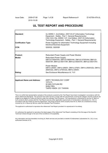
<strong>UL</strong> <strong>TEST</strong> <strong>REPORT</strong> <strong>AND</strong> <strong>PROCEDURE</strong><br />
Standard: <strong>UL</strong> 60950-1, 2nd Edition, 2007-03-27 (Information Technology<br />
Equipment - Safety - Part 1: General Requirements)<br />
CSA C22.2 No. 60950-1-07, 2nd Edition, 2007-03 (Information<br />
Technology Equipment - Safety - Part 1: General Requirements)<br />
Certification Type: Power Supplies for Information Technology Equipment Including<br />
Electrical Business Equipment<br />
CCN: QQGQ2, QQGQ8<br />
Product: Redundant Power Supply and Power Module<br />
Model: Redundant Power Supply:<br />
DM1U2-5500V4H, DM1U2-5650V4H, DM1U2-5750V4H, BM1U2-<br />
5500V4H, BM1U2-5501V4H, BM1U2-5500V4V, BM1U2-5501V4V.<br />
Power Module:<br />
DM1U-2500V, DM1U-2650V, DM1U-2750V, DM1U-2500V(D), DM1U-<br />
2650V(D), DM1U-2750V(D), BM1U-2500V.<br />
Rating: See Enclosure Miscellaneous Id. 7-01<br />
Applicant Name and Address: <strong>ZIPPY</strong> TECHNOLOGY CORP<br />
10TH FL<br />
50 MIN CHYUAN RD<br />
SHIN-TIEN<br />
TAIPEI HSIEN 231 TAIWAN<br />
This is to certify that representative samples of the products covered by this Test Report have been investigated in accordance with the<br />
above referenced Standards. The products have been found to comply with the requirements covering the category and the products are<br />
judged to be eligible for Follow-Up Service under the indicated Test Procedure. The manufacturer is authorized to use the <strong>UL</strong> Mark on<br />
such products which comply with this Test Report and any other applicable requirements of Underwriters Laboratories Inc. ('<strong>UL</strong>') in<br />
accordance with the Follow-Up Service Agreement. Only those products which properly bear the <strong>UL</strong> Mark are considered as being<br />
covered by <strong>UL</strong>'s Follow-Up Service under the indicated Test Procedure.<br />
The applicant is authorized to reproduce the referenced Test Report provided it is reproduced in its entirety.<br />
<strong>UL</strong> authorizes the applicant to reproduce the latest pages of the referenced Test Report consisting of the first page of the Specific<br />
Technical Criteria through to the end of the Conditions of Acceptability.<br />
Any information and documentation involving <strong>UL</strong> Mark services are provided on behalf of Underwriters Laboratories Inc. (<strong>UL</strong>) or any<br />
authorized licensee of <strong>UL</strong>.<br />
Copyright © 2010
Issue Date: 2009-07-08<br />
2010-10-26<br />
Page 2 of 28 Report Reference # E143756-A76-<strong>UL</strong><br />
Terence She<br />
Prepared by: Underwriters Laboratories Inc.<br />
Rex Lin<br />
Reviewed by: Underwriters Laboratories Inc.<br />
Copyright © 2010
Issue Date: 2009-07-08<br />
2010-10-26<br />
Page 3 of 28 Report Reference # E143756-A76-<strong>UL</strong><br />
Supporting Documentation<br />
The following documents located at the beginning of this Procedure supplement the requirements of this Test<br />
Report:<br />
A. Authorization - The Authorization page may include additional Factory Identification Code markings.<br />
B. Generic Inspection Instructions -<br />
i. Part AC details important information which may be applicable to products covered by this Procedure.<br />
Products described in this Test Report must comply with any applicable items listed unless otherwise<br />
stated in the body of this Test Report.<br />
ii. Part AE details any requirements which may be applicable to all products covered by this Procedure.<br />
Products described in this Test Report must comply with any applicable items listed unless otherwise<br />
stated in the body of each Test Report.<br />
iii. Part AF details the requirements for the <strong>UL</strong> Certification Mark which is not controlled by the technical<br />
standard used to investigate these products. Products are permitted to bear only the Certification<br />
Mark(s) corresponding to the countries for which it is certified, as indicated in each Test Report.<br />
Product Description<br />
Power Module: The product are composed of DC fan, power supply board and housed in metal chassis.<br />
Redundant Power Supply:<br />
The product is a 1+1 hot-swappable / hot-pluggable DC to DC Power Supply for using in Information<br />
Technology Equipment (ITE).<br />
Model Differences<br />
Models DM1U-2500V, DM1U-2650V, DM1U-2750V, DM1U-2500V(D), DM1U-2650V(D), DM1U-2750V(D),<br />
BM1U-2500V are Power Modules, which are similar mutually except for input/output ratings and model<br />
designation. See Enclosure Miscellaneous Id. 7-01 in detail.<br />
Models DM1U2-5500V4H, DM1U2-5650V4H, DM1U2-5750V4H, BM1U2-5500V4H, BM1U2-5501V4H,<br />
BM1U2-5500V4V, BM1U2-5501V4V are Redundant Power Supply, which are similar mutually except for<br />
input/output ratings and model designation. See Enclosure Miscellaneous Id. 7-01 in detail.<br />
Model BM1U-2500V is similar Model DM1U-2500V, except for input ratings, EMI board, L3, L4, T2, T4,<br />
schematic and PCB layout, front chassis and model designation.<br />
Model BM1U2-5501V4H is similar Model BM1U2-5500V4H, except for output ratings and model designation.<br />
Model BM1U2-5500V4H is similar Model DM1U2-5500V4H, except for input rating, backboard and model<br />
designation.<br />
Output Type of Power Module:<br />
(1) Connector for Models DM1U-2500V, DM1U-2650V, DM1U-2750V, BM1U-2500V. Refer to Enclosure Id<br />
3-03.<br />
(2) Wires with connectors for Models DM1U-2500V(D), DM1U-2650V(D), DM1U-2750V(D). Refer to<br />
Enclosure Id 3-06.<br />
Model nomenclature for Power Module:<br />
- The capital "D" and "B" of "DM1U-" and "BM1U-", which denotes DC input;<br />
- The numerical "2" of "DM1U-2500V" and "BM1U-2500V", which denotes 2 outputs;<br />
- The numerical "650" of "DM1U-2650V", which denotes total maximum output power consumption (ex. 650<br />
Watt);<br />
- The numerical "750" of "DM1U-2750V", which denotes total maximum output power consumption (ex. 750
Issue Date: 2009-07-08<br />
2010-10-26<br />
Page 4 of 28 Report Reference # E143756-A76-<strong>UL</strong><br />
Watt).<br />
All Redundant Power Supply Models are composed of 2 Power Modules maximum, only Models DM1U-<br />
2500V, DM1U-2650V, DM1U-2750V, BM1U-2500V used.<br />
Model nomenclature for Redundant Power Supply:<br />
- The numerical "2" of "DM1U2-", which means 1+1 Redundant Power Supply.<br />
- The numerical "5" of "DM1U2-5", which denotes 5 outputs;<br />
- The numerical "500" of "DM1U2-5500", which denotes total maximum output power consumption (ex. 500<br />
Watt), and composed of 2 Power Modules Model DM1U-2500V maximum;<br />
- The numerical "650" of "DM1U2-5650", which denotes total maximum output power consumption (ex. 650<br />
Watt), and composed of 2 Power Modules Model DM1U-2650V maximum;<br />
- The numerical "750" of "DM1U2-5750", which denotes total maximum output power consumption (ex. 750<br />
Watt), and composed of 2 Power Modules Model DM1U-2750V maximum;<br />
- The last letter"H" denotes Power Module arrange horizontally;<br />
- The last letter"V" denotes Power Module arrange vertically.<br />
Technical Considerations<br />
Equipment mobility : for building-in<br />
Connection to the mains : To be evaluated in end product<br />
Operating condition : continuous<br />
Access location : N/A<br />
Over voltage category (OVC) : --<br />
Mains supply tolerance (%) or absolute mains supply values : no tolerance declared by manufacturer<br />
Tested for IT power systems : No<br />
IT testing, phase-phase voltage (V) : --<br />
Class of equipment : Class I (earthed)<br />
Considered current rating (A) : 20 A<br />
Pollution degree (PD) : PD 2<br />
IP protection class : IP X0<br />
Altitude of operation (m) : up to 3100 m
Issue Date: 2009-07-08<br />
2010-10-26<br />
Page 5 of 28 Report Reference # E143756-A76-<strong>UL</strong><br />
Altitude of test laboratory (m) : up to 3100 m<br />
Mass of equipment (kg) : 1 kg (For Models DM1U-2500V, DM1U-2650V, DM1U-2750V, DM1U-<br />
2500V(D), DM1U-2650V(D), DM1U-2750V(D)); 3 kg (For Models DM1U2-5500V4H, DM1U2-<br />
5650V4H, DM1U2-5750V4H); 3.1 kg for Models BM1U2-5500V4H, BM1U2-5501V4H; 3.8 kg for<br />
Models BM1U2-5500V4V, BM1U2-5501V4V.<br />
The product was submitted and evaluated for use at the maximum ambient temperature (Tma)<br />
permitted by the manufacturer’s specification of: (1) 35 degree C for Models DM1U2-5750V4H,<br />
DM1U-2750V, DM1U-2750V(D); (2) 50 degree C for Models DM1U2-5650V4H, DM1U2-5500V4H,<br />
DM1U-2650V, DM1U-2650V(D), DM1U-2500V, DM1U-2500V(D), BM1U-2500V, BM1U2-5500V4H,<br />
BM1U2-5501V4H, BM1U2-5500V4V, BM1U2-5501V4V.<br />
The product is intended for use on the following power systems: DC mains supply<br />
The following are available from the Applicant upon request: Installation (Safety) Instructions /<br />
Manual. , Specific data sheets for LED indicators that are class I and operate at wavelength in the<br />
400-710 nm range.<br />
An investigation of the protective bonding terminals has been conducted 40 A specified by the<br />
manufacturer.<br />
Engineering Conditions of Acceptability<br />
For use only in or with complete equipment where the acceptability of the combination is determined by<br />
Underwriters Laboratories Inc. When installed in an end-product, consideration must be given to the<br />
following:<br />
The end-product Electric Strength Test is to be based upon a maximum working voltage of: Input -<br />
Output: 99 Vrms, 176 Vpk<br />
The following secondary output circuits are SELV: All outputs.<br />
The following secondary output circuits are at hazardous energy levels: +12 Vdc output of all models<br />
The following secondary output circuits are at non-hazardous energy levels: All outputs except for<br />
+12 Vdc of all models<br />
The following output terminals were referenced to earth during performance testing: Input (0V) and<br />
Output common return<br />
The power supply terminals and/or connectors are: Suitable for factory wiring only<br />
The investigated Pollution Degree is: 2
Issue Date: 2009-07-08<br />
2010-10-26<br />
Page 6 of 28 Report Reference # E143756-A76-<strong>UL</strong><br />
Proper bonding to the end-product main protective earthing termination is: Required<br />
An investigation of the protective bonding terminals has: Been conducted<br />
The following magnetic devices (e.g. transformers or inductor) are provided with an OBJY2 insulation<br />
system with the indicated rating greater than Class A (105°C): Transformer T4 and T2 (Class B)<br />
The following end-product enclosures are required: Mechanical, Fire, Electrical<br />
The following input terminals were evaluated as suitable for direct connection to the DC Mains<br />
Supply: Input connector or terminal block.<br />
The equipment is suitable for direct connection to: DC mains supply<br />
The product was investigated to the following additional standards: IEC 60664-1: 2007 clearance<br />
requirements for 3100 m above sea level. The required clearance is multiplied by the altitude<br />
correction factor (1.155), as specified in Table A.2.<br />
The power supply is expected to use in hot-swappable condition and clause 4.3.5 Connector Current<br />
Interruption Test has been conducted.<br />
The power supply with internal insulation serving as Reinforced/Double insulation between input and<br />
output cirucit.<br />
Protective Current Rating of the power supply was 16A/20A as specified by the manufacturer.<br />
An investigation of the protective bonding terminals has been conducted 40 A specified by the<br />
manufacturer.<br />
Additional Information<br />
Air flow of DC fan may be used inward or outward.<br />
Markings and instructions<br />
Clause Title Marking or Instruction Details<br />
Power rating - Ratings<br />
Power rating -<br />
Company identification<br />
Model<br />
Power rating -<br />
Ratings (voltage, frequency/dc, current)<br />
Listee's or Recognized company's name, Trade Name, Trademark or File<br />
Number<br />
Model Number
Issue Date: 2009-07-08<br />
2010-10-26<br />
Page 7 of 28 Report Reference # E143756-A76-<strong>UL</strong><br />
Fuses - Rating<br />
1.7.9 Multiple power<br />
sources<br />
Special Instructions to <strong>UL</strong> Representative<br />
Rated current and voltage and type located on or adjacent to fuse or<br />
fuseholder.<br />
Following statement indicated on redundant units.<br />
Warning: Multiple power sources. Refer to service manual before servicing.<br />
Following statement included in service manual.<br />
Redundant power supplies are provided with more than one power source.<br />
Disconnect one power supply cord and pull out this power module when just a<br />
single power module has failed and servicing and maintaining that module.<br />
Disconnect all power supply cords before servicing the complete unit if whole<br />
redundant unit servicing is necessary.<br />
Inspect the transformer(s) listed in BD1.1 per AA1.1- (C). When the tests are conducted at other location,<br />
inspect test record and specification sheet provided by the component manufacturer. Verify the specification<br />
sheet indicates 100% routine test specified in BD1.1 be conducted at the component manufacturer.<br />
Production-Line Testing Requirements<br />
Electric Strength Test Special Constructions - Refer to Generic Inspection Instructions, Part AC for<br />
further information.<br />
Model Component<br />
All models Transformer T2,<br />
T4<br />
Removable<br />
Parts Test probe location<br />
-- Input winding - Output<br />
winding<br />
V<br />
rms V dc<br />
Earthing Continuity Test Exemptions - This test is not required for the following models:<br />
All models.<br />
Electric Strength Test Exemptions - This test is not required for the following models:<br />
All models.<br />
200<br />
0<br />
Test Time,<br />
s<br />
-- 1<br />
Electric Strength Test Component Exemptions - The following solid-state components may be<br />
disconnected from the remainder of the circuitry during the performance of this test:<br />
--<br />
Sample and Test Specifics for Follow-Up Tests at <strong>UL</strong><br />
Model Component Material Test Sample(s)<br />
-- -- -- -- -- --<br />
Test<br />
Specifics
Issue Date: 2009-07-08<br />
2010-10-26<br />
Page 8 of 28 Report Reference # E143756-A76-<strong>UL</strong>
Issue Date: 2009-07-08<br />
2010-10-26<br />
Page 9 of 28 Report Reference # E143756-A76-<strong>UL</strong><br />
TABLE: List of Critical Components<br />
Object/part No. Manufacturer/<br />
trademark<br />
Redundant Power<br />
Supply<br />
Zippy Technology<br />
Corp.<br />
type/model technical data CCN Marks of<br />
Conformity<br />
DM1U2-5500V4H,<br />
DM1U2-5650V4H,<br />
DM1U2-5750V4H,<br />
BM1U2-5500V4H,<br />
BM1U2-5501V4H,<br />
BM1U2-5500V4V,<br />
BM1U2-5501V4V<br />
Consist of the following critical parts. -- --<br />
01. Redundant Chassis -- -- Metal (Nickel Plated Iron), secured together by<br />
screws. Overall approximately 355 by 106 by 41<br />
mm, minimum 0.9 mm thick. Can be provided with<br />
maximum two Power Modules. Provide with<br />
several slot ventilation openings on both side, each<br />
approximately maximum 25 by 3 mm; provide with<br />
several slot ventilation openings on top, each<br />
approximately maximum 25 by 3 mm; and 12.3 by<br />
103 mm.<br />
02. Rating Marking - Various Various Rated minimum 65 degree C, suitable for surface<br />
Label<br />
applied to chassis.<br />
-- --<br />
PGDQ2 or PGJI2 <strong>UL</strong><br />
03. Output Wires Various Various Secondary Wiring, Low voltage secondary (SEC,<br />
ELV, SELV), rated minimum 80 degree C, minimum<br />
30 V, minimum 18 AWG, FEP, PTFE, PVC, TFE,<br />
neoprene, or surface marked VW-1.<br />
AVLV2 <strong>UL</strong><br />
04. Printed Wiring<br />
Boards (Secondary Back<br />
Board)<br />
Various Various Rated minimum V-1, minimum 105 degree C. ZPMV2 <strong>UL</strong><br />
05. Connectors (CN5, Positronic Industries GFSH89F4 Mounted on Back Board, mated with output ECBT2 <strong>UL</strong><br />
CN6)<br />
Inc<br />
connector of Power Module. Rated 250V, 16A.<br />
er Module Zippy Technology DM1U-2500V, Consist of the following critical parts. -- --<br />
Corp.<br />
DM1U-2650V,<br />
DM1U-2750V,<br />
DM1U-2500V(D),<br />
DM1U-2650V(D),
Issue Date: 2009-07-08<br />
2010-10-26<br />
Page 10 of 28 Report Reference # E143756-A76-<strong>UL</strong><br />
Object/part No. Manufacturer/<br />
trademark<br />
type/model technical data CCN Marks of<br />
Conformity<br />
01. Chassis (For Input --<br />
DM1U-2750V(D),<br />
BM1U-2500V<br />
-- Metal (Nickel Plated Iron and Aluminum<br />
-- --<br />
Connector Type) (For<br />
Magnesium alloy). Three pieces construction and<br />
Models DM1U-2500V,<br />
secured together by screws. Overall approximately<br />
DM1U-2650V, DM1U-<br />
300 by 50.5 by 40 mm, minimum 0.9 mm thick.<br />
2750V, DM1U-<br />
Provide with 2 slot ventilation openings on top,<br />
2500V(D), DM1U-<br />
each approximately 15 by 3 mm; provide with 23<br />
2650V(D), DM1U-<br />
ventilation openings on front (input / fan side), each<br />
2750V(D))<br />
maximum 9 by 4.5 mm.<br />
01a. Chassis (For Input -- -- Metal (Nickel Plated Iron and Aluminum<br />
-- --<br />
Terminal Block Type)<br />
Magnesium alloy). Three pieces construction and<br />
(For Models DM1U-<br />
secured together by screws. Overall approximately<br />
2500V, DM1U-2650V,<br />
300 by 50.5 by 40 mm, minimum 0.9 mm thick.<br />
DM1U-2750V, DM1U-<br />
Provide with 2 slot ventilation openings on top,<br />
2500V(D), DM1U-<br />
each approximately 15 by 3 mm; provide with 23<br />
2650V(D), DM1U-<br />
ventilation openings on front (input / fan side), each<br />
2750V(D))<br />
maximum 6 by 4.0 mm.<br />
02. Rating Marking - Various Various Rated minimum 65 degree C, suitable for surface PGDQ2 or PGJI2 <strong>UL</strong><br />
Label<br />
applied to chassis.<br />
03. Handle -- -- Plastic, U-shaped. Rated minimum HB, minimum<br />
85 degree C. Overall approximate 37.5 by 25 mm,<br />
5.5 mm diameter. Secured to front chassis by<br />
screws.<br />
QMFZ2 <strong>UL</strong><br />
04. Earth Screw (For -- -- Metal. Minimum 4 mm diameter (M4 size). -- --<br />
Input Terminal Block<br />
Type)<br />
Secured to front chassis with washer.<br />
05. DC Fan (Airflow can Sanyo Denki Co Ltd 9GV0412P3Jxxy One provided. Rated 12 Vdc, 0.6 A, minimum GPWV2 <strong>UL</strong><br />
be inward or outward)<br />
(xx = 00 to 99) (y 20.84 CFM. Secured to front chassis by screw,<br />
(For Models DM1U-<br />
= blank or 1) fans leads provided with Insulating Tubing /<br />
2500V, DM1U-2650V,<br />
DM1U-2750V, DM1U-<br />
2500V(D), DM1U-<br />
Sleeving, minimum 0.4 mm thick.
Issue Date: 2009-07-08<br />
2010-10-26<br />
Page 11 of 28 Report Reference # E143756-A76-<strong>UL</strong><br />
Object/part No. Manufacturer/<br />
trademark<br />
2650V(D), DM1U-<br />
2750V(D))<br />
05a. DC Fan (Airflow<br />
can be inward or<br />
outward) (Alternate)<br />
05b. DC Fan (Airflow<br />
can be inward or<br />
outward) (Alternate)<br />
05c. DC Fan (Airflow can<br />
be inward or outward)<br />
(Alternate)<br />
05d. DC Fan (Airflow<br />
can be inward or<br />
outward) (Alternate)<br />
05e. DC Fan (Airflow<br />
can be inward or<br />
outward) (Alternate)<br />
06. Input Terminal Block<br />
(For Models DM1U-<br />
2500V, DM1U-2650V,<br />
DM1U-2750V, DM1U-<br />
2500V(D), DM1U-<br />
2650V(D), DM1U-<br />
2750V(D))<br />
06a. Input Terminal<br />
Block (For Models<br />
DM1U-2500V, DM1U-<br />
2650V, DM1U-2750V,<br />
Sanyo Denki Co Ltd 9GV0412P3Kxxy<br />
(xx = 00 to 99) (y<br />
= blank or 1)<br />
Sanyo Denki Co Ltd 9GV0412K3DXXy<br />
*(xx = 00 to 99)*(y<br />
= blank or 1)<br />
ADDA Corp AD0412VB-<br />
B53DS<br />
Sunonwealth Electric<br />
Machine Industry Co<br />
Ltd<br />
Sanyo Denki Co Ltd 9GE0412P3Jxx<br />
(xx = 01 to 99)<br />
Dinkle Enterprise Co<br />
Ltd<br />
Howder Electric Co<br />
Ltd<br />
type/model technical data CCN Marks of<br />
Conformity<br />
One provided. Rated 12 Vdc, 0.84 A, minimum<br />
23.31 CFM. Secured to front chassis by screw,<br />
fans leads provided with Insulating Tubing /<br />
Sleeving, minimum 0.4 mm thick.<br />
One provided. Rated 12 Vdc, 0.84 A, minimum<br />
23.31 CFM. Secured to front chassis by screw,<br />
fans leads provided with Insulating Tubing /<br />
Sleeving, minimum 0.4 mm thick.<br />
One provided. Rated 12 Vdc, 0.8 A, 27 CFM.<br />
Secured to front chassis by screw, fans leads<br />
provided with Insulating Tubing / Sleeving,<br />
minimum 0.4 mm thick.<br />
PMD1204PQB1-A One provided. Rated 12 Vdc, 0.72 A, 24 CFM.<br />
Secured to front chassis by screw, fans leads<br />
provided with Insulating Tubing / Sleeving,<br />
minimum 0.4 mm thick.<br />
One provided. Rated 12 Vdc, 0.65 A, minimum<br />
21.19 CFM. Secured to front chassis by screw,<br />
fans leads provided with Insulating Tubing /<br />
Sleeving, minimum 0.4 mm thick.<br />
DT-45 Rated 300V, 25A. Secured to front chassis by<br />
screws.<br />
HD-122 Rated 300V, 25A. Secured to front chassis by<br />
screws.<br />
GPWV2 <strong>UL</strong><br />
GPWV2 <strong>UL</strong><br />
GPWV2 <strong>UL</strong><br />
GPWV2 <strong>UL</strong><br />
GPWV2 <strong>UL</strong><br />
XCFR2 <strong>UL</strong><br />
XCFR2 <strong>UL</strong>
Issue Date: 2009-07-08<br />
2010-10-26<br />
Page 12 of 28 Report Reference # E143756-A76-<strong>UL</strong><br />
Object/part No. Manufacturer/<br />
trademark<br />
DM1U-2500V(D),<br />
DM1U-2650V(D),<br />
DM1U-2750V(D))<br />
(Alternate)<br />
06b. Input Connector<br />
(Substitute Input<br />
Terminal) (For Models<br />
DM1U-2500V, DM1U-<br />
2650V, DM1U-<br />
2500V(D), DM1U-<br />
2650V(D))<br />
07. Bonding wire (For<br />
Input Connector Type)<br />
(For Models DM1U-<br />
2500V, DM1U-2650V,<br />
DM1U-2750V, DM1U-<br />
2500V(D), DM1U-<br />
2650V(D), DM1U-<br />
2750V(D))<br />
08. Internal DC Input<br />
Wires (For Models<br />
DM1U-2500V, DM1U-<br />
2650V, DM1U-2750V,<br />
DM1U-2500V(D),<br />
DM1U-2650V(D),<br />
DM1U-2750V(D))<br />
Positronic Industries,<br />
Inc.<br />
type/model technical data CCN Marks of<br />
Conformity<br />
PLB06 Rated 600V maximum, 23A. Secured to front<br />
chassis by screws.<br />
Various Various Green/yellow lead. Rated VW-1, minimum 14<br />
AWG, minimum 105 degree C, minimum 300 Vac.<br />
One end secured then soldered to Input Connector;<br />
other end terminates in closed-loop, double crimptype<br />
connector, secured to chassis with dedicated<br />
threaded post, screw nut and lock-washer.<br />
Various Various FEP, PTEF, PVC, TFE, neoprene or surface<br />
marked rated VW-1, min. 12 AWG, minimum 105<br />
degree C, minimum 300 V. One end secured then<br />
soldered to Input Connector or Input Terminal<br />
Block; other end terminates secured then soldered<br />
to Main Board.<br />
09. LED Wires Various Various Secondary Wiring, Low voltage secondary (SEC,<br />
ELV, SELV), rated minimum 80 degree C, minimum<br />
30 V, FEP, PTFE, PVC, TFE, neoprene, or surface<br />
marked VW-1. Provided with Insulating Tubing /<br />
10. Position of Insulation<br />
Sheet<br />
Sleeving, minimum 0.4 mm thick.<br />
-- -- Two provided. One provided between Main Board<br />
and bottom chassis. See Enclosure ID 4-01 for<br />
dimension details; other one secured on top<br />
ECBT2 <strong>UL</strong><br />
AVLV2 <strong>UL</strong><br />
AVLV2 <strong>UL</strong><br />
AVLV2 <strong>UL</strong><br />
-- --
Issue Date: 2009-07-08<br />
2010-10-26<br />
Page 13 of 28 Report Reference # E143756-A76-<strong>UL</strong><br />
Object/part No. Manufacturer/<br />
trademark<br />
type/model technical data CCN Marks of<br />
Conformity<br />
11. Materials of Sabic Innovative FR1<br />
chassis by adhesive-backed. See Enclosure ID 4-<br />
02 for dimension details<br />
Rated minimum V-2, minimum 0.25 mm thick. QMFZ2 <strong>UL</strong><br />
Insulation Sheet Plastics Us L L C<br />
11a. Materials of Formex,Div Of Il Tool FORMEX Rated minimum V-2, minimum 0.25 mm thick. QMFZ2 <strong>UL</strong><br />
Insulation Sheet Works Inc,Frmrly<br />
(Alternate)<br />
Fastex,Div Of Il Tool<br />
Works Inc<br />
12. Silicon Rubber Various Various Two provided, minimum V-2. Secured on bottom<br />
chassis.<br />
QMFZ2 <strong>UL</strong><br />
13. Insulation Tape 3M Company 1350-1, 1350F-1 Wrapped on top of capacitors (C4, C4A) OANZ2 <strong>UL</strong><br />
(Optional)<br />
Electrical Markets Div<br />
(EMD)<br />
14. Printed Wiring Various Various Rated minimum V-1, minimum 105 degree C. ZPMV2 <strong>UL</strong><br />
Boards<br />
Consists of Main Board, daughter card (CN1, CN3,<br />
CN2 and CN9) and several secondary daughter<br />
cards. The daughter cards secured and soldered<br />
to Main Board vertically; Main Board secured to<br />
bottom chassis by screws and kept minimum 3.5<br />
mm height to chassis.<br />
15. Y-Capacitors (CY1, Walsin Technology AC, AH Soldered on Main Board. Rated maximum 4700 FOWX2 <strong>UL</strong><br />
CY2, CY3 and CY4) Corp<br />
pF, minimum 250 V, minimum 125 degree C.<br />
(Optional)<br />
Marked with an Y1 or Y2 and Certified by VDE,<br />
DEMKO or SEV. (Meets IEC60384-14.)<br />
15a. Y-Capacitors (CY1,<br />
CY2, CY3 and CY4)<br />
(Optional) (Alternate)<br />
TDK Corp CD Same as above. FOWX2 <strong>UL</strong><br />
15b. Y-Capacitors (CY1, Welson Industrial Co WD Same as above. FOWX2 <strong>UL</strong><br />
CY2, CY3 and CY4)<br />
(Optional) (Alternate)<br />
Ltd<br />
15c. Y-Capacitors (CY1, Success Electronics SE Same as above. FOWX2 <strong>UL</strong><br />
CY2, CY3 and CY4)<br />
(Optional) (Alternate)<br />
Co Ltd
Issue Date: 2009-07-08<br />
2010-10-26<br />
Page 14 of 28 Report Reference # E143756-A76-<strong>UL</strong><br />
Object/part No. Manufacturer/<br />
trademark<br />
type/model technical data CCN Marks of<br />
Conformity<br />
16. Capacitors (C17,<br />
C12, C24) (Optional)<br />
-- -- Rated minimum 100 V, maximum 2.2 uF. -- --<br />
17. Bleeder Resistors Various Various SMD Type. R1, R2 in series, each rated 56 k ohm, -- --<br />
(R1, R2)<br />
minimum 1/4 W.<br />
18. Fuse (F1) Cooper Bussmann ABC Rated 125 Vdc, F 30 A. Fuse provided with JDYX2 <strong>UL</strong><br />
Inc<br />
Insulating Tubing / Sleeving.<br />
19. Varistor<br />
Epcos (Zhuhai Ftz) S14K95 Rated 95Vac, 150Vdc. The body and lead VZCA2 <strong>UL</strong><br />
(VZ1)(Optional) Co Ltd<br />
provided with Insulation Tubing / Sleeving.<br />
19a. Varistor (VZ1) Nippon Chemi-con TND14V-151K Rated 95 Vac, 150 Vdc. The body provided with VZCA2 <strong>UL</strong><br />
(Optional) (Alternate) Corp<br />
Insulation Tubing / Sleeving.<br />
19b. Varistor (VZ1) Joyin Co., Ltd. 14N151k Rated 95 Vac, 125 Vdc. The body provided with VZCA2 <strong>UL</strong><br />
(Optional) (Alternate)<br />
Insulation Tubing / Sleeving.<br />
19b. Varistor (VZ1) Nippon Chemi-con TNR15G151K Rated 95 Vac, 150 Vdc. The body provided with VZCA2 <strong>UL</strong><br />
(Optional) (Alternate) Corp<br />
Insulation Tubing / Sleeving.<br />
19c. Varistor (VZ1) Thinking Electronic TVR14151 Rated 95 Vac, 156 Vdc. The body provided with VZCA2 <strong>UL</strong><br />
(Optional) (Alternate) Industrial Co Ltd<br />
Insulation Tubing / Sleeving.<br />
20. Inductor (L2) -- -- Rated minimum 130 degree C. Core, Ferrite. Coil,<br />
copper magnet wire wound on core. See enclosure<br />
ID 4-03 for details.<br />
-- --<br />
21. Inductor (T3) -- -- Rated minimum 130 degree C. Core, Ferrite. Coil,<br />
copper magnet wire wound on core. See enclosure<br />
ID 4-04 for details.<br />
-- --<br />
22. Inductor (L3) (For -- -- Rated minimum 105 degree C. Core, Ferrite. Coil, -- --<br />
Models DM1U-2500V,<br />
copper magnet wire wound on core. See enclosure<br />
DM1U-2650V, DM1U-<br />
2750V, DM1U-<br />
2500V(D), DM1U-<br />
2650V(D), DM1U-<br />
2750V(D))<br />
ID 4-05 for details.<br />
23. Inductor (L4) (For -- -- Rated minimum 130 degree C. Core, Ferrite. Coil, -- --<br />
Models DM1U-2500V,<br />
copper magnet wire wound on core. See enclosure<br />
DM1U-2650V, DM1U-<br />
2750V, DM1U-<br />
ID 4-06 for details.
Issue Date: 2009-07-08<br />
2010-10-26<br />
Page 15 of 28 Report Reference # E143756-A76-<strong>UL</strong><br />
Object/part No. Manufacturer/<br />
trademark<br />
type/model technical data CCN Marks of<br />
Conformity<br />
2500V(D), DM1U-<br />
2650V(D), DM1U-<br />
2750V(D))<br />
24. Transistors (Q1, Q2) -- -- Rated 180 to 96A, minimum 100 V. Secured to<br />
Heat sink (H1) by screw.<br />
-- --<br />
25. Heat Sink (H1) -- -- Tin Plated Brass and aluminum, secured to<br />
Transistors (Q1, Q2) by screw and soldered to<br />
PWB. Overall approximately 27.7 by 21 by 32 mm,<br />
2.0 mm thick. (H1 is input circuitry.)<br />
-- --<br />
26. Transistors (Q5, Q8, -- -- Rated 140 A, minimum 100 V. Secured to Heat -- --<br />
Q13, Q14, Q15, Q16)<br />
sink (H2) by screw.<br />
27. Heat Sink (H2) -- -- Tin Plated Brass and aluminum, secured to<br />
Transistors (Q5, Q8, Q13, Q14, Q15, Q16) by<br />
screw and soldered to PWB. Overall approximately<br />
70 by 18.7 by 32 mm, minimum 1.0 mm thick. (H2<br />
is input circuitry.)<br />
-- --<br />
28. Electrolytic<br />
-- -- Integral pressure relief. Rated 1200 uF, minimum -- --<br />
Capacitors (C4, C4A)<br />
100 V, minimum 105 degree C.<br />
29. Transistor (Q37) -- -- Rated 18 A, minimum 200V. -- --<br />
30. Drive Transformer<br />
(T1) (Secured on CN9<br />
Board)<br />
31. Bridge-Capacitor<br />
(CY5) (Optional)<br />
31a. Bridge-Capacitor<br />
(CY5) (Optional)<br />
(Alternate)<br />
31b. Bridge-Capacitor<br />
(CY5) (Optional)<br />
(Alternate)<br />
-- -- Rated minimum 105 degree C. See enclosure ID<br />
4-07 for details.<br />
Walsin Technology<br />
Corp<br />
AH Rated maximum 4700 pF, minimum 250 Vac<br />
minimum 125 degree C. Marked with an Y1 and<br />
Certified by VDE, DEMKO or SEV. (Meets<br />
IEC60384-14.)<br />
-- --<br />
FOWX2 <strong>UL</strong><br />
TDK Corp CD Same as above. FOWX2 <strong>UL</strong><br />
Welson Industrial Co<br />
Ltd<br />
WD Same as above. FOWX2 <strong>UL</strong><br />
31c. Bridge-Capacitor Success Electronics SE Same as above. FOWX2 <strong>UL</strong>
Issue Date: 2009-07-08<br />
2010-10-26<br />
Page 16 of 28 Report Reference # E143756-A76-<strong>UL</strong><br />
Object/part No. Manufacturer/<br />
trademark<br />
(CY5) (Optional)<br />
(Alternate)<br />
32. Transformer (T2)<br />
(For Models DM1U-<br />
2500V, DM1U-2650V,<br />
DM1U-2750V, DM1U-<br />
2500V(D), DM1U-<br />
2650V(D), DM1U-<br />
2750V(D))<br />
32-1. Insulation system<br />
of Transformer (T2)<br />
32-2. Insulation Tape of<br />
Transformer (T2)<br />
32-3. Triple insulation<br />
wire of Transformer (T2)<br />
32-4. Tube of<br />
Transformer (T2)<br />
32a-1. Insulation system<br />
of Transformer (T2)<br />
(Alternate)<br />
32a-2. Insulation Tape of<br />
Transformer (T2)<br />
32a-3. Triple insulation<br />
wire of Transformer (T2)<br />
32a-4. Tube of<br />
Transformer (T2)<br />
33. Transformer (T4)<br />
(For Models DM1U-<br />
2500V, DM1U-2650V,<br />
DM1U-2750V, DM1U-<br />
Co Ltd<br />
type/model technical data CCN Marks of<br />
Conformity<br />
-- -- Open type construction. Core, Ferrite. Coil, copper<br />
magnet wire wound on core. See Enclosure ID 4-<br />
08 for construction details.<br />
-- --<br />
Li Chieh Electronic<br />
Industrial Co Ltd<br />
HIS-8A Class B. OBJY2 <strong>UL</strong><br />
3M Company<br />
Electrical Markets Div<br />
(EMD)<br />
1350F-1 Rated 130 degree C. OANZ2 <strong>UL</strong><br />
Furukawa Electric Co<br />
Ltd<br />
TEX-E Primary. Rated 130 degree C. OBJT2 <strong>UL</strong><br />
Zeus Industrial<br />
Products Inc<br />
TFE-TW-300 Rated 200 degree C. YDPU2 <strong>UL</strong><br />
Large Magnetic<br />
Electronic Co Ltd<br />
(Chief Superior<br />
Insustrial Co., Ltd.)<br />
SBI 4.2 Class B. OBJY2 <strong>UL</strong><br />
Jingjiang Yahua<br />
Pressure Sensitive<br />
Glue Co Ltd<br />
CT Rated 130 degree C. OANZ2 <strong>UL</strong><br />
Furukawa Electric Co<br />
Ltd<br />
TEX-E Primary. Rated 130 degree C. OBJT2 <strong>UL</strong><br />
Great Holding<br />
Industrial Co Ltd<br />
TFL Rated 200 degree C. YDPU2 <strong>UL</strong><br />
-- -- Open type construction. Core, Ferrite. Coil, copper --<br />
magnet wire wound on bobbin. See Enclosure ID<br />
4-09 for construction details.<br />
--
Issue Date: 2009-07-08<br />
2010-10-26<br />
Page 17 of 28 Report Reference # E143756-A76-<strong>UL</strong><br />
Object/part No. Manufacturer/<br />
trademark<br />
2500V(D), DM1U-<br />
2650V(D), DM1U-<br />
2750V(D))<br />
33-1. Insulation system<br />
of Transformer (T4)<br />
33-2. Insulation Tape of<br />
Transformer (T4)<br />
33-3. Bobbin of<br />
Transformer (T4)<br />
33-4. Triple insulation<br />
wire of Transformer (T4)<br />
33-5. Varnish of<br />
Transformer (T4)<br />
33-6. Tube of<br />
Transformer (T4)<br />
33-7. Windings of<br />
Transformer (T4)<br />
33a-1. Insulation system<br />
of Transformer (T4)<br />
(Alternate)<br />
33a-2. Insulation Tape of<br />
Transformer (T4)<br />
33a-3. Bobbin of<br />
Transformer (T4)<br />
33a-4. Triple insulation<br />
wire of Transformer (T4)<br />
33a-5. Varnish of<br />
Transformer (T4)<br />
33a-6. Tube of<br />
Transformer (T4)<br />
type/model technical data CCN Marks of<br />
Conformity<br />
Li Chieh Electronic<br />
Industrial Co Ltd<br />
HIS-8A Class B. OBJY2 <strong>UL</strong><br />
3M Company<br />
Electrical Markets Div<br />
(EMD)<br />
1350F-1 Rated 130 degree C. OANZ2 <strong>UL</strong><br />
Hitachi Chemical Co CP-J-8800 Phenolic. Minimum V-2, minimum 0.71 mm thick, QFMZ2 <strong>UL</strong><br />
Ltd<br />
rated 150 degree C.<br />
Furukawa Electric Co<br />
Ltd<br />
TEX-E Secondary. Rated 130 degree C. OBJT2 <strong>UL</strong><br />
Hitachi Chemical Co<br />
Ltd<br />
WP-2952F-2G Rated 130 degree C. OBOR2 <strong>UL</strong><br />
Zeus Industrial<br />
Products Inc<br />
TFE-TW-300 Rated 200 degree C. YDPU2 <strong>UL</strong><br />
Various Various Rated 130 degree C. OBMW2 <strong>UL</strong><br />
Large Magnetic<br />
Electronic Co Ltd<br />
(Chief Superior<br />
Insustrial Co., Ltd.)<br />
SBI 4.2 Class B. OBJY2 <strong>UL</strong><br />
Jingjiang Yahua<br />
Pressure Sensitive<br />
Glue Co Ltd<br />
CT Rated 130 degree C. OANZ2 <strong>UL</strong><br />
Sumitomo Bakelite PM-9820 Phenolic. Minimum V-2, minimum 0.71 mm thick, QFMZ2 <strong>UL</strong><br />
Co Ltd<br />
rated 150 degree C.<br />
Furukawa Electric Co<br />
Ltd<br />
TEX-E Secondary. Rated 130 degree C. OBJT2 <strong>UL</strong><br />
John C Dolph Co BC-346A Rated 200 degree C. OBOR2 <strong>UL</strong><br />
Great Holding<br />
Industrial Co Ltd<br />
TFL Rated 200 degree C. YDPU2 <strong>UL</strong>
Issue Date: 2009-07-08<br />
2010-10-26<br />
Page 18 of 28 Report Reference # E143756-A76-<strong>UL</strong><br />
Object/part No. Manufacturer/<br />
trademark<br />
type/model technical data CCN Marks of<br />
Conformity<br />
33a-7. Windings of<br />
Transformer (T4)<br />
Various Various Rated 130 degree C. OBMW2 <strong>UL</strong><br />
33b-1. Insulation system Li Tai Electronic CIS.04 Class B. OBJY2 <strong>UL</strong><br />
of Transformer (T4)<br />
(Alternate)<br />
Enterprise Co, Ltd<br />
33b-2. Bobbin of Sumitomo Bakelite PM-9820 Phenolic. Minimum V-2, minimum 0.71 mm thick, QMFZ2 <strong>UL</strong><br />
Transformer (T4) Co Ltd<br />
rated 150 degree C.<br />
33b-3. Insulation Tape of Symbio Inc<br />
Transformer (T4)<br />
35660Y Rated 130 degree C. OANZ2 <strong>UL</strong><br />
33b-4. Insulation Tape of 3M Company 1350F-1 Rated 130 degree C. OANZ2 <strong>UL</strong><br />
Transformer (T4) Electrical Markets Div<br />
(Alternate)<br />
(EMD)<br />
33b-7. Varnish of<br />
Transformer (T4)<br />
John C Dolph Co BC-346A Rated 130 degree C. OBOR2 <strong>UL</strong><br />
33b-8. Tube of<br />
Great Holding TFL Rated 200 degree C. External side provided with YDPU2 <strong>UL</strong><br />
Transformer (T4) Industrial Co Ltd<br />
Insulation Tubing / Sleeving.<br />
33b-9. Windings of<br />
Transformer (T4)<br />
Various Various Rated 130 degree C. OBMW2 <strong>UL</strong><br />
33b-10. Triple insulation<br />
wire of Transformer (T4)<br />
Cosmolink Co Ltd TIW-M Rated 130 degree C. OBJT2 <strong>UL</strong><br />
34. Optical Isolator (U11) Sharp Corp<br />
Electronic<br />
Components Group<br />
PC817 Rated Isolation minimum 5000 V ac. FPQU2 <strong>UL</strong><br />
34a. Optical Isolator Everlight Electronics EL817 series Rated Isolation minimum 5000 V ac. FPQU2 <strong>UL</strong><br />
(U11) (Alternate) Co Ltd<br />
34b. Optical Isolator Fairchild<br />
H11A817 series Rated Isolation minimum 5000 V ac. FPQU2 <strong>UL</strong><br />
(U11) (Alternate) Semiconductor Corp.<br />
34c. Optical Isolator Lite-On Technology LTV 817 Rated Isolation minimum 5000 V ac. FPQU2 <strong>UL</strong><br />
(U11) (Alternate) Corp<br />
34d. Optical Isolator Cosmo Electronics K1010 Rated Isolation minimum 5000 V ac. FPQU2 <strong>UL</strong><br />
(U11) (Alternate) Corp<br />
35. Optical Isolators (U2, Vishay<br />
TCLT1000series, Rated Isolation minimum 5000 V ac. Double FPQU2 <strong>UL</strong><br />
U9 and U20)<br />
Semiconductor TCLT1001series, protection. U2, U9 and U20 mounted on daughter
Issue Date: 2009-07-08<br />
2010-10-26<br />
Page 19 of 28 Report Reference # E143756-A76-<strong>UL</strong><br />
Object/part No. Manufacturer/<br />
trademark<br />
35a. Optical Isolators<br />
(U2, U9 and U20)<br />
(Alternate)<br />
36. Non-Optical Isolators<br />
(U19)<br />
37. Output Connector<br />
(CN11) (For Models<br />
DM1U-2500V, DM1U-<br />
2650V, DM1U-2750V)<br />
38. Insaulation Tubing /<br />
Sleeving<br />
39. Secondary Internal<br />
Wiring<br />
40. Connector and<br />
Receptacles (secondary<br />
ELV/SELV circuits) (For<br />
models DM1U-2750V(D)<br />
DM1U-2650V(D),<br />
DM1U-2500V(D))<br />
40a. Connector and<br />
Receptacles (secondary<br />
Gmbh TCLT1002series,<br />
TCLT1003series,<br />
TCLT1004series,<br />
TCLT1005series,<br />
TCLT1006series,<br />
TCLT1007series,<br />
TCLT1008series,<br />
TCLT1009series<br />
Fairchild<br />
Semiconductor Corp<br />
type/model technical data CCN Marks of<br />
Conformity<br />
card (CN2).<br />
H11A817 series Rated Isolation minimum 5000 V ac. U2, U9 and<br />
U20 mounted on daughter card (CN2).<br />
Analog Devices Inc ADuM240 series Rated Isolation minimum 5000 V ac. Double<br />
Protection type. The IC mounted on daughter card<br />
Positronic Industries<br />
Inc<br />
FPQU2 <strong>UL</strong><br />
FPPT2 <strong>UL</strong><br />
GFSH89M4<br />
CN2.<br />
250V, 16A. ECBT2 <strong>UL</strong><br />
Various Various FEP, PTFE, PVC, TFE, neoprene, polyimide or<br />
marked VW-1; minimum 105 degree C, minimum<br />
300 V.<br />
Various Various (Secondary) Low voltage secondary (SEC, ELV,<br />
SELV), rated minimum 85 degree C, minimum 60<br />
V, FEP, PTFE, PVC, TFE, neoprene, or surface<br />
marked VW-1.<br />
Various Various Copper alloy pins housed in bodies of plastic rated<br />
min. V-2.<br />
YDPU2 <strong>UL</strong><br />
AVLV2 <strong>UL</strong><br />
QMFZ2 <strong>UL</strong><br />
Various Various -- ECBT2, RTRT2,<br />
DUXR or DUXR2<br />
<strong>UL</strong>
Issue Date: 2009-07-08<br />
2010-10-26<br />
Page 20 of 28 Report Reference # E143756-A76-<strong>UL</strong><br />
Object/part No. Manufacturer/<br />
trademark<br />
type/model technical data CCN Marks of<br />
Conformity<br />
ELV/SELV circuits) (For<br />
models DM1U-2750V(D)<br />
DM1U-2650V(D),<br />
DM1U-2500V(D))<br />
(Alternate)<br />
41. Thermal State (TS1) Seki Controls Co Ltd ST-22 Rated 250V, 1A, 150 degree C XAPX2 <strong>UL</strong><br />
42. Chassis (For Input<br />
Connector Type) (For<br />
Model BM1U-2500V)<br />
42a. Chassis (For Input<br />
Terminal Block Type)<br />
(For Model BM1U-<br />
2500V)<br />
44. Input Terminal Block<br />
(Alternate) (For Models<br />
BM1U-2500V<br />
44b. Input Connector<br />
(Substitute Input<br />
Terminal) (For Models<br />
DM1U-2750V, DM1U-<br />
2750V(D), BM1U-<br />
2500V)<br />
45. Internal DC Input<br />
Wires (For Model BM1U-<br />
2500V)<br />
-- -- Metal (Nickel Plated Iron and Aluminum<br />
Magnesium alloy). Three pieces construction and<br />
secured together by screws. Overall approximately<br />
300 by 50.5 by 40 mm, minimum 0.9 mm thick.<br />
Provide with 26 ventilation openings on front (input /<br />
fan side), each maximum 5 by 4 mm.<br />
-- -- Metal (Nickel Plated Iron and Aluminum<br />
Magnesium alloy). Three pieces construction and<br />
secured together by screws. Overall approximately<br />
300 by 50.5 by 40 mm, minimum 0.9 mm thick.<br />
Provide with 2 slot ventilation openings on top,<br />
each approximately 15 by 3 mm; provide with 22<br />
ventilation openings on front (input / fan side), each<br />
Dinkle Enterprise Co<br />
Ltd<br />
Positronic Industries,<br />
Inc.<br />
maximum5 by 4 mm.<br />
DT-66-C11W Rated 300V, 40A. Secured to EMI board and front<br />
chassis by soldering and physical fit<br />
PLBH06 Rated 600V maximum, 32A. Secured to front<br />
chassis by screws For Models DM1U-2750V,<br />
DM1U-2750V(D); Secured to EMI board and front<br />
chassis by soldering and physical fit for Model<br />
BM1U-2500V.<br />
Various Various FEP, PTEF, PVC, TFE, neoprene or surface<br />
marked rated VW-1, min. 12 AWG, minimum 105<br />
degree C, minimum 300 V. One end secured then<br />
soldered to EMI Board; other end terminates<br />
-- --<br />
-- --<br />
XCFR2 <strong>UL</strong><br />
ECBT2 <strong>UL</strong><br />
AVLV2 <strong>UL</strong>
Issue Date: 2009-07-08<br />
2010-10-26<br />
Page 21 of 28 Report Reference # E143756-A76-<strong>UL</strong><br />
Object/part No. Manufacturer/<br />
trademark<br />
46. Varistor (VZ1, VZ2)<br />
(VZ2 only for Model<br />
BM1U-2500V) (Optional)<br />
46a. Varistor (VZ1, VZ2)<br />
(VZ2 only for Model<br />
BM1U-2500V)<br />
(Optional) (Alternate)<br />
46b. Varistor (VZ1, VZ2)<br />
(VZ2 only for Model<br />
BM1U-2500V)<br />
(Optional) (Alternate)<br />
46b. Varistor (VZ1, VZ2)<br />
(VZ2 only for Model<br />
BM1U-2500V)<br />
(Optional) (Alternate)<br />
46c. Varistor (VZ1, VZ2)<br />
(VZ2 only for Model<br />
BM1U-2500V)<br />
(Optional) (Alternate)<br />
47. Inductor (L3) (For<br />
Model BM1U-2500V)<br />
48. Inductor (L4) (For<br />
Model BM1U-2500V)<br />
49. EMI Board (For<br />
Model BM1U-2500V)<br />
Epcos (Zhuhai Ftz)<br />
Co Ltd<br />
Nippon Chemi-con<br />
Corp<br />
type/model technical data CCN Marks of<br />
Conformity<br />
secured then soldered to Main Board.<br />
S14K95 Rated 95Vac, 150Vdc. The body and lead<br />
provided with Insulation Tubing / Sleeving.<br />
TND14V-151K Rated 95 Vac, 150 Vdc. The body provided with<br />
Insulation Tubing / Sleeving.<br />
Joyin Co., Ltd. 14N151k Rated 95 Vac, 125 Vdc. The body provided with<br />
Insulation Tubing / Sleeving.<br />
Nippon Chemi-con<br />
Corp<br />
Thinking Electronic<br />
Industrial Co Ltd<br />
TNR15G151K Rated 95 Vac, 150 Vdc. The body provided with<br />
Insulation Tubing / Sleeving.<br />
TVR14151 Rated 95 Vac, 156 Vdc. The body provided with<br />
Insulation Tubing / Sleeving.<br />
-- -- Rated minimum 105 degree C. Core, Ferrite. Coil,<br />
copper magnet wire wound on core. See enclosure<br />
ID 4-10 for details.<br />
-- -- Rated minimum 130 degree C. Core, Ferrite. Coil,<br />
copper magnet wire wound on core. See enclosure<br />
ID 4-11 for details.<br />
Various Various Rated minimum V-1, minimum 105 degree C.<br />
Secured to front chassis by two screws. Consist of<br />
the following critical parts.<br />
VZCA2 <strong>UL</strong><br />
VZCA2 <strong>UL</strong><br />
VZCA2 <strong>UL</strong><br />
VZCA2 <strong>UL</strong><br />
VZCA2 <strong>UL</strong><br />
-- --<br />
-- --<br />
ZPMV2 <strong>UL</strong><br />
49-1. Inductor (L1) -- -- Rated minimum 105 degree C. Core, Ferrite. Coil,<br />
copper magnet wire wound on core. See enclosure<br />
ID 4-12 for details.<br />
-- --<br />
49-2. Varistor (VZ1) Epcos (Zhuhai Ftz) S14K95 Rated 95Vac, 150Vdc. The body and lead VZCA2 <strong>UL</strong>
Issue Date: 2009-07-08<br />
2010-10-26<br />
Page 22 of 28 Report Reference # E143756-A76-<strong>UL</strong><br />
Object/part No. Manufacturer/<br />
trademark<br />
type/model technical data CCN Marks of<br />
Conformity<br />
(Optional) Co Ltd provided with Insulation Tubing / Sleeving. (E321126)<br />
49-2a. Varistor (VZ1) Nippon Chemi-con TND14V-151K Rated 95 Vac, 150 Vdc. The body provided with VZCA2 <strong>UL</strong><br />
(Optional) (Alternate) Corp<br />
Insulation Tubing / Sleeving.<br />
(E323623)<br />
49-2b. Varistor (VZ1) Joyin Co., Ltd. 14N151k Rated 95 Vac, 125 Vdc. The body provided with VZCA2 <strong>UL</strong><br />
(Optional) (Alternate)<br />
Insulation Tubing / Sleeving.<br />
(E325508)<br />
49-2b. Varistor (VZ1) Nippon Chemi-con TNR15G151K Rated 95 Vac, 150 Vdc. The body provided with VZCA2 <strong>UL</strong><br />
(Optional) (Alternate) Corp<br />
Insulation Tubing / Sleeving.<br />
(E323623)<br />
49-2c. Varistor (VZ1) Thinking Electronic TVR14151 Rated 95 Vac, 156 Vdc. The body provided with VZCA2 <strong>UL</strong><br />
(Optional) (Alternate) Industrial Co Ltd<br />
Insulation Tubing / Sleeving.<br />
(E314979)<br />
49-3. Capacitors (C1,<br />
C2, C3) (Optional)<br />
-- -- Rated minimum 100 V, maximum 2.2 uF. -- --<br />
49-4. Bleeder Resistors -- -- SMD Type. R1, R2 in series, each rated 56 k ohm, -- --<br />
(R1, R2)<br />
minimum 1/4 W.<br />
50. Position of Insulation -- -- Provided between EMI Board and chassis. See -- --<br />
Sheet for Input<br />
Connector Type (For<br />
Model BM1U-2500V)<br />
Enclosure ID 4-13 for dimension details.<br />
50-1. Position of -- -- Provided between EMI Board and chassis. See -- --<br />
Insulation Sheet for Input<br />
Terminal Block Type<br />
(For Model BM1U-<br />
2500V)<br />
Enclosure ID 4-14 for dimension details.<br />
51. Materials of Sabic Innovative FR1 Rated minimum V-2, minimum 0.25 mm thick. QMFZ2 <strong>UL</strong><br />
Insulation Sheet Plastics Us L L C<br />
51a. Materials of Formex,Div Of Il Tool FORMEX Rated minimum V-2, minimum 0.25 mm thick. QMFZ2 <strong>UL</strong><br />
Insulation Sheet Works Inc,Frmrly<br />
(Alternate)<br />
Fastex,Div Of Il Tool<br />
Works Inc<br />
52. Transformer (T2) -- -- Open type construction. Core, Ferrite. Coil, copper -- --<br />
(For Model BM1U-<br />
magnet wire wound on core. See Enclosure ID 4-<br />
2500V)<br />
15 for construction details.<br />
52-1. Insulation system Li Chieh Electronic DASH 2 B-5 Class B. OBJY2 <strong>UL</strong><br />
of Transformer (T2) Industrial Co Ltd
Issue Date: 2009-07-08<br />
2010-10-26<br />
Page 23 of 28 Report Reference # E143756-A76-<strong>UL</strong><br />
Object/part No. Manufacturer/<br />
trademark<br />
52-2. Insulation Tape of<br />
Transformer (T2)<br />
type/model technical data CCN Marks of<br />
Conformity<br />
3M Company<br />
Electrical Markets Div<br />
(EMD)<br />
1350F-1 Rated 130 degree C. OANZ2 <strong>UL</strong><br />
Various Various Primary. Rated 130 degree C. OBMW2 <strong>UL</strong><br />
52-3. Windings of<br />
Transformer (T2)<br />
52-4. Tube of<br />
Great Holding TFT Rated 200 degree C. Minimum 0.4 mm thick. YDPU2 <strong>UL</strong><br />
Transformer (T2) Industrial Co Ltd<br />
52-5. Tube of<br />
Great Holding TFS Rated 200 degree C. For external winding leads. YDPU2 <strong>UL</strong><br />
Transformer (T2) Industrial Co Ltd<br />
Min. 0.4 mm thick.<br />
52a-1. Insulation system Large Magnetic SBI 4.2 Class B. OBJY2 <strong>UL</strong><br />
of Transformer (T2) Electronic Co Ltd<br />
(Alternate)<br />
(Chief Superior<br />
Insustrial Co., Ltd.)<br />
52a-2. Insulation Tape of Jingjiang Yahua CT Rated 130 degree C. OANZ2 <strong>UL</strong><br />
Transformer (T2) Pressure Sensitive<br />
Glue Co Ltd<br />
52a-3. Windings of<br />
Transformer (T2)<br />
Various Various Primary. Rated 130 degree C. OBMW2 <strong>UL</strong><br />
52a-4. Tube of<br />
Great Holding TFL Rated 200 degree C. YDPU2 <strong>UL</strong><br />
Transformer (T2) Industrial Co Ltd<br />
52a-5. Tube of<br />
Great Holding TFS Rated 200 degree C. For external winding lead. YDPU2 <strong>UL</strong><br />
Transformer (T2) Industrial Co Ltd<br />
Min. 0.4 mm thick.<br />
53. Transformer (T4) -- -- Open type construction. Core, Ferrite. Coil, copper -- --<br />
(For Model BM1U-<br />
magnet wire wound on bobbin. See Enclosure ID<br />
2500V)<br />
4-16 for construction details.<br />
53-1. Insulation system Large Magnetic SBI 4.2 Class B. OBJY2 <strong>UL</strong><br />
of Transformer (T4) Electronic Co Ltd<br />
(Alternate)<br />
(Chief Superior<br />
Insustrial Co., Ltd.)<br />
53-2. Insulation Tape of Jingjiang Yahua CT Rated 130 degree C. OANZ2 <strong>UL</strong><br />
Transformer (T4) Pressure Sensitive<br />
Glue Co Ltd<br />
53-3. Bobbin of Sumitomo Bakelite PM-9820 Phenolic. Minimum V-2, minimum 0.71 mm thick, QFMZ2 <strong>UL</strong>
Issue Date: 2009-07-08<br />
2010-10-26<br />
Page 24 of 28 Report Reference # E143756-A76-<strong>UL</strong><br />
Object/part No. Manufacturer/<br />
trademark<br />
type/model technical data CCN Marks of<br />
Conformity<br />
Transformer (T4) Co Ltd rated 150 degree C.<br />
53-4. Triple insulation Furukawa Electric Co TEX-E Secondary. Rated 130 degree C. OBJT2 <strong>UL</strong><br />
wire of Transformer (T4) Ltd<br />
53-5. Varnish of<br />
Transformer (T4)<br />
John C Dolph Co BC-346A Rated 200 degree C. OBOR2 <strong>UL</strong><br />
53-6. Tube of<br />
Great Holding TFL Rated 200 degree C. YDPU2 <strong>UL</strong><br />
Transformer (T4) Industrial Co Ltd<br />
53-7. Windings of<br />
Transformer (T4)<br />
Various Various Rated 130 degree C. OBMW2 <strong>UL</strong><br />
53a-1. Insulation system Dongguan<br />
SBI 4.2 Class B. OBJY2 <strong>UL</strong><br />
of Transformer (T4) Zhangmutou Hong<br />
(Alternate)<br />
Chan<br />
53a-2. Insulation Tape of Jingjiang Yahua CT Rated 130 degree C. OANZ2 <strong>UL</strong><br />
Transformer (T4) Pressure Sensitive<br />
Glue Co Ltd<br />
53a-2a. Insulation Tape 3M Company 1350F-1, 1350F-2 Rated 130 degree C. OANZ2 <strong>UL</strong><br />
of Transformer (T4) Electrical Markets Div<br />
(EMD)<br />
53a-3. Bobbin of Sumitomo Bakelite PM-9820 Phenolic. Minimum V-2, minimum 0.71 mm thick, QFMZ2 <strong>UL</strong><br />
Transformer (T4) Co Ltd<br />
rated 150 degree C.<br />
53a-4. Triple insulation Furukawa Electric Co TEX-E Secondary. Rated 130 degree C. OBJT2 <strong>UL</strong><br />
wire of Transformer (T4) Ltd<br />
53a-4a. Triple insulation Totoku Electric Co TIW-2 Secondary. Rated 130 degree C. OBJT2 <strong>UL</strong><br />
wire of Transformer (T4) Ltd<br />
53a-5. Varnish of Elantas Electrical V1380FC Rated minimum 130 degree C. OBOR2 <strong>UL</strong><br />
Transformer (T4) Insulation Elantas<br />
Pdg Inc<br />
53a-6. Tube of<br />
Great Holding TFL Rated 200 degree C. YDPU2 <strong>UL</strong><br />
Transformer (T4) Industrial Co Ltd<br />
53a-7. Windings of<br />
Transformer (T4)<br />
Various Various Rated 130 degree C. OBMW2 <strong>UL</strong><br />
53b-1. Insulation system Li Chieh Electronic HIA-8A Class B. OBJY2 <strong>UL</strong><br />
of Transformer (T4) Industrial Co Ltd
Issue Date: 2009-07-08<br />
2010-10-26<br />
Page 25 of 28 Report Reference # E143756-A76-<strong>UL</strong><br />
Object/part No. Manufacturer/<br />
trademark<br />
53b-2. Insulation Tape of<br />
Transformer (T4)<br />
53b-3. Windings of<br />
Transformer (T4)<br />
53b-4. Tube of<br />
Transformer (T4)<br />
53b-5. Varnish of<br />
Transformer (T4)<br />
53b-6. Triple insulation<br />
wire of Transformer (T4)<br />
53a-7. Bobbin of<br />
Transformer (T4)<br />
54. Secondary Inductor<br />
(L1, L2) (For Models<br />
BM1U2-5501V4H and<br />
BM1U2-5501V4V)<br />
54a. Winding of<br />
Secondary Inductor (L1,<br />
L2) (For Models BM1U2-<br />
5501V4H and BM1U2-<br />
5501V4V)<br />
type/model technical data CCN Marks of<br />
Conformity<br />
3M Company<br />
Electrical Markets Div<br />
(EMD)<br />
1350F-1 Rated 130 degree C. OANZ2 <strong>UL</strong><br />
Various Various Rated 130 degree C. OBMW2 <strong>UL</strong><br />
Zeus Industrial<br />
Products Inc<br />
TFE-TW-300 Rated 200 degree C. YDPU2 <strong>UL</strong><br />
Hitachi Chemical Co., WP-2952F-2G<br />
Ltd<br />
Rated 130 degree C. OBJS2 <strong>UL</strong><br />
Furukawa Electric Co<br />
Ltd<br />
TEX-E Primary. Rated 130 degree C. OBJT2 <strong>UL</strong><br />
Hitachi Co.,Ltd CP-J-8800 Phenolic. Minimum V-2, minimum 0.71 mm thick,<br />
rated 150 degree C.<br />
QFMZ2 <strong>UL</strong><br />
-- -- 130 degree C -- --<br />
Various Various Rated 130 degree C. OBMW2 <strong>UL</strong>
Issue Date: 2009-07-08<br />
2010-10-26<br />
Page 26 of 28 Report Reference # E143756-A76-<strong>UL</strong><br />
Enclosures<br />
Type Supplement Id Description<br />
Photographs 3-01 Overall Fornt view (used Input terminal block) of Power Module,<br />
Models DM1U-2500V, DM1U-2650V, DM1U-2750V<br />
Photographs 3-02 Alternate Overall Fornt view (used Input Connector) of Power<br />
Module, Models DM1U-2500V, DM1U-2650V, DM1U-2750V<br />
Photographs 3-03 Overall Rear view of Power Module, Models DM1U-2500V, DM1U-<br />
2650V, DM1U-2750V<br />
Photographs 3-04 Overall Front view (used Input terminal block) of Power Module,<br />
Models DM1U-2500V(D), DM1U-2650V(D), DM1U-2750V(D)<br />
Photographs 3-05 Alternate Overall Front view (used Input Connector) of Power<br />
Module, Models DM1U-2500V(D), DM1U-2650V(D), DM1U-<br />
2750V(D)<br />
Photographs 3-06 Overall Rear view of Power Module, Models DM1U-2500V(D),<br />
DM1U-2650V(D), DM1U-2750V(D)<br />
Photographs 3-07 Internal View of Power Module, Models DM1U-2500V, DM1U-<br />
2650V, DM1U-2750V<br />
Photographs 3-08 PWB component side of Power Module, Models DM1U-2500V,<br />
DM1U-2650V, DM1U-2750V<br />
Photographs 3-09 PWB solder side of Power Module, Models DM1U-2500V, DM1U-<br />
2650V, DM1U-2750V<br />
Photographs 3-10 Internal View of Power Module, Models DM1U-2500V(D), DM1U-<br />
2650V(D), DM1U-2750V(D)<br />
Photographs 3-11 PWB component side of Power Module, Models DM1U-2500V(D),<br />
DM1U-2650V(D), DM1U-2750V(D)<br />
Photographs 3-12 CN2 Control Board view 1 (across input and output circuit) of all<br />
Power Modules<br />
Photographs 3-13 CN2 Control Board view 2 (across input and output circuit) of all<br />
Power Modules<br />
Photographs 3-14 Overall Front view of Redundant Power Supply, Models DM1U2-<br />
5500V4H, DM1U2-5650V4H, DM1U2-5750V4H<br />
Photographs 3-15 Overall Rear view of Redundant Power Supply, Models DM1U2-<br />
5500V4H, DM1U2-5650V4H, DM1U2-5750V4H<br />
Photographs 3-16 Secondary Back board view 1 of Redundant Power Supply,<br />
Models DM1U2-5500V4H, DM1U2-5650V4H, DM1U2-5750V4H<br />
Photographs 3-17 Secondary Back board view 2 of Redundant Power Supply,<br />
Models DM1U2-5500V4H, DM1U2-5650V4H, DM1U2-5750V4H<br />
Photographs 3-18 Overall Fornt view (use Input terminal block) of Power Module,<br />
Model BM1U-2500V<br />
Photographs 3-19 Overall Fornt view (use Input connector) of Power Module, Model<br />
BM1U-2500V
Issue Date: 2009-07-08<br />
2010-10-26<br />
Page 27 of 28 Report Reference # E143756-A76-<strong>UL</strong><br />
Photographs 3-20 Internal View of Power Module, Model BM1U-2500V<br />
Photographs 3-21 PWB component side of Power Module, Model BM1U-2500V<br />
Photographs 3-22 PWB solder side of Power Module, Model BM1U-2500V<br />
Photographs 3-23 PWB component side of EMI board (For Model BM1U-2500V with<br />
input connector)<br />
Photographs 3-24 PWB trace side of EMI board (For Model BM1U-2500V with input<br />
connector)<br />
Photographs 3-25 PWB component side of EMI board (For Model BM1U-2500V with<br />
input terminal block)<br />
Photographs 3-26 PWB trace side of EMI board (For Model BM1U-2500V with input<br />
terminal block)<br />
Photographs 3-27 Overall Front view of Redundant Power Supply, Models BM1U2-<br />
5500V4H, BM1U2-5501V4H<br />
Photographs 3-28 Overall Front view of Redundant Power Supply, Models BM1U2-<br />
5500V4V, BM1U2-5501V4V<br />
Photographs 3-29 Secondary Back board view 1 of Redundant Power Supply,<br />
Models BM1U2-5500V4H, BM1U2-5501V4H<br />
Photographs 3-30 Secondary Back board view 2 of Redundant Power Supply,<br />
Models BM1U2-5500V4H, BM1U2-5501V4H<br />
Photographs 3-31 Secondary Back board view 1 of Redundant Power Supply,<br />
Models BM1U2-5500V4V, BM1U2-5501V4V<br />
Photographs 3-32 Secondary Back board view 2 of Redundant Power Supply,<br />
Models BM1U2-5500V4V, BM1U2-5501V4V<br />
Diagrams 4-01 Insulation sheet between main board and internal bottom chassis<br />
of all Power Modules<br />
Diagrams 4-02 Insulation sheet located between main board amd internal top<br />
chassis of all Power Modules<br />
Diagrams 4-03 Inductor (L2) (provided 3 copies, they were all the same except for<br />
different manufacturer) of all Power Modules<br />
Diagrams 4-04 Inductor (T3) (provided 3 copies, they were all the same except for<br />
different manufacturer) of all Power Modules<br />
Diagrams 4-05 Inductor (L3) (For Models DM1U-2500V, DM1U-2650V, DM1U-<br />
2750V, DM1U-2500V(D), DM1U-2650V(D), DM1U-2750V(D))<br />
Diagrams 4-06 Inductor (L4)(For Models DM1U-2500V, DM1U-2650V, DM1U-<br />
2750V, DM1U-2500V(D), DM1U-2650V(D), DM1U-2750V(D))<br />
Diagrams 4-07 Drive Transformer (T1) (provided 2 copies, they were all the same<br />
except for different manufacturer) of all Power Modules<br />
Diagrams 4-08 Transformer (T2) (For Models DM1U-2500V, DM1U-2650V,<br />
DM1U-2750V, DM1U-2500V(D), DM1U-2650V(D), DM1U-<br />
2750V(D))<br />
Diagrams 4-09 Transformer (T4)(For Models DM1U-2500V, DM1U-2650V,<br />
DM1U-2750V, DM1U-2500V(D), DM1U-2650V(D), DM1U-<br />
2750V(D))<br />
Diagrams 4-10 Inductor (L3) (For Model BM1U-2500V)
Issue Date: 2009-07-08<br />
2010-10-26<br />
Page 28 of 28 Report Reference # E143756-A76-<strong>UL</strong><br />
Diagrams 4-11 Inductor (L4) (For Model BM1U-2500V)<br />
Diagrams 4-12 Inductor (L1) (For Model BM1U-2500V)<br />
Diagrams 4-13 Insulation Sheet for Input Connector Type provided between EMI<br />
Board and chassis (For Model BM1U-2500V)<br />
Diagrams 4-14 Insulation Sheet for Input Terminal Block Type provided between<br />
EMI Board and chassis (For Model BM1U-2500V)<br />
Diagrams 4-15 Transformer (T2) of Module (For Model BM1U-2500V)<br />
Diagrams 4-16 Transformer (T4) of Module (For Model BM1U-2500V)<br />
Schematics + PWB 5-01 Main Board of Power Modules (Models DM1U-2500V, DM1U-<br />
2650V, DM1U-2750V, DM1U-2500V(D), DM1U-2650V(D), DM1U-<br />
2750V(D))<br />
Schematics + PWB 5-02 CN2 Control Board (across input and output circuit) of all Power<br />
Modules<br />
Schematics + PWB 5-03 CN5, CN9 and CN1 Board (located on input circuit) of all Power<br />
Modules<br />
Schematics + PWB 5-04 Secondary Back board of Redundant Power Supplies (Models<br />
DM1U2-5500V4H, DM1U2-5650V4H, DM1U2-5750V4H)<br />
Schematics + PWB 5-05 Main Board of Power Modules (For Model BM1U-2500V)<br />
Schematics + PWB 5-06 Secondary Back board of Redundant Power Supplies (For Models<br />
BM1U2-5500V4H, BM1U2-5501V4H)<br />
Schematics + PWB 5-07 Secondary Back board of Redundant Power Supplies (For Models<br />
BM1U2-5500V4V, BM1U2-5501V4V)<br />
Schematics + PWB 5-08 EMI Board for Input Connector Type (For Model BM1U-2500V)<br />
Schematics + PWB<br />
Manuals<br />
5-09 EMI Board for Input Terminal Block Type (For Model BM1U-<br />
2500V)<br />
Miscellaneous 7-01 Models and rating list<br />
Miscellaneous 7-02 Test Result Tables (for reference only)<br />
Miscellaneous 7-03 Test Result Tables (for Models BM1U2-5500V4H, BM1U2-<br />
5501V4H, BM1U2-5500V4V, BM1U2-5501V4V, BM1U-2500V)
Issue Date: 2009-07-08<br />
2010-10-26<br />
Page 1 of 10 Report Reference # E143756-A76-<strong>UL</strong><br />
Enclosure<br />
National Differences<br />
USA / Canada
Issue Date: 2009-07-08<br />
2010-10-26<br />
Page 2 of 10 Report Reference # E143756-A76-<strong>UL</strong><br />
IEC 60950-1<br />
SubClause Difference + Test Result - Remark Verdict<br />
USA / Canada - Differences to IEC 60950-1:2005 (Second Edition)<br />
1.1 Equipment able to be installed in accordance with<br />
the National Electrical Code ANSI/NFPA 70 and the<br />
Canadian Electrical Code, Part1, and when<br />
applicable, the National Electrical Safety Code,<br />
IEEE C2.<br />
1.1.1 Equipment able to be installed in accordance with<br />
ANSI/NFPA 75 and NEC Art. 645 unless intended<br />
for use outside of computer room and provided with<br />
such instructions.<br />
1.1.2 Equipment in wire-line communication facilities<br />
serving high-voltage electric power stations<br />
operating at greater than 1kV are excluded.<br />
1.1.2 Special requirements apply to equipment intended<br />
for use outdoors.<br />
1.4.14 For Pluggable Equipment Type A, the protection in<br />
the installation is assumed to be 20 A.<br />
1.5.1 All IEC standards for components identified in<br />
Annex P.1 replaced by the relevant requirements of<br />
CSA and <strong>UL</strong> component standards in Annex P.1.<br />
1.5.1 All IEC standards for components identified in<br />
Annex P.2 alternatively satisfied by the relevant<br />
requirements of CSA and <strong>UL</strong> component standards<br />
in Annex P.2.<br />
1.5.5 Interconnecting cables acceptable for the<br />
application regarding voltage, current, temperature,<br />
flammability, mechanical serviceability and the like.<br />
1.5.5 For other than limited power and TNV circuits, the<br />
type of output circuit identified for output connector.<br />
1.5.5 External cable assemblies that exceed 3.05 m in<br />
length to be types specified in the NEC and CEC.<br />
1.5.5 Detachable external interconnecting cables 3.05 m<br />
or less in length and provided with equipment<br />
marked to identify the responsible organization and<br />
the designation for the cable.<br />
1.5.5 Building wiring and cable for use in ducts, plenums<br />
and other air handling space subject to special<br />
requirements and excluded from scope.<br />
1.5.5 Telephone line and extension cords and the like<br />
comply with <strong>UL</strong> 1863 and CSA C22.2 No. 233.<br />
1.6.1.2 Equipment intended for connection to a d.c. power<br />
(mains) distribution system is subject to special<br />
Pass<br />
Pass<br />
N/A<br />
N/A<br />
N/A<br />
Pass<br />
Pass<br />
N/A<br />
N/A<br />
N/A<br />
N/A<br />
N/A<br />
N/A<br />
Pass
Issue Date: 2009-07-08<br />
2010-10-26<br />
Page 3 of 10 Report Reference # E143756-A76-<strong>UL</strong><br />
IEC 60950-1<br />
SubClause Difference + Test Result - Remark Verdict<br />
circuit classification requirements (e.g., TNV-2)<br />
1.6.1.2 Earthing of d.c. powered equipment provided. Pass<br />
1.7 Lamp replacement information indicated on<br />
lampholder in operator access area.<br />
1.7.1 Special marking format for equipment intended for<br />
use on a supply system with an earthed neutral and<br />
more than one phase conductor.<br />
1.7.1 Equipment voltage rating not higher than rating of<br />
the plug except under special conditions.<br />
1.7.6 Special fuse replacement marking for operator<br />
accessible fuses.<br />
1.7.7 Identification of terminal connection of the<br />
equipment earthing conductor.<br />
1.7.7 Connectors and field wiring terminals for external<br />
Class 2 or Class 3 circuits provided with marking<br />
indicating minimum Class of wiring to be used.<br />
1.7.7 Marking located adjacent to terminals and visible<br />
during wiring.<br />
2.1.1.1 Bare TNV conductive parts in the interior of<br />
equipment normally protected against contact by a<br />
cover intended for occasional removal are exempt<br />
provided instructions include directions for<br />
disconnection of TNV prior to removal of the cover.<br />
2.3.1.b Other telecommunication signaling systems (e.g.,<br />
message waiting) than described in 2.3.1(b) are<br />
subject to M.4.<br />
2.3.1.b For TNV-2 and TNV-3 circuits with other than<br />
ringing signals and with voltages exceeding 42.4 Vp<br />
or 60 V d.c., the maximum current limit through a<br />
2000 Ohm or greater resistor with loads<br />
disconnected is 7.1 mA peak or 30 mA d.c. under<br />
normal conditions.<br />
2.3.1.b Limits for measurements across 5000 ohm resistor<br />
in the event of a single fault are replaced after 200<br />
ms with the limits of M.3.1.4.<br />
2.3.2.1 In the event of a single fault, the limits of 2.2.3 apply<br />
to SELV circuits and accessible conductive parts.<br />
2.3.2.4 Enamel coating on signal transformer winding wire<br />
allowed as an alternative to Basic insulation in<br />
specific telecommunication applications when<br />
subjected to special construction requirements and<br />
routine testing.<br />
N/A<br />
N/A<br />
N/A<br />
N/A<br />
Pass<br />
N/A<br />
Pass<br />
N/A<br />
N/A<br />
N/A<br />
N/A<br />
N/A<br />
N/A
Issue Date: 2009-07-08<br />
2010-10-26<br />
Page 4 of 10 Report Reference # E143756-A76-<strong>UL</strong><br />
IEC 60950-1<br />
SubClause Difference + Test Result - Remark Verdict<br />
2.5 Overcurrent protection device required for Class 2<br />
and Class 3 limiting in accordance with the NEC, or<br />
for a Limited Power Source, not interchangeable<br />
with devices of higher ratings if operator<br />
replaceable.<br />
2.6 Equipment having receptacles for output a.c. power<br />
connectors generated from an internal separately<br />
derived source have the earthed (grounded) circuit<br />
conductor suitably bonded to earth.<br />
2.6.3.3 For Pluggable Equipment Type A, if a) b) or c) are<br />
not applicable, the current rating of the circuit is<br />
taken as 20 A<br />
2.6.3.4 Capacity of connection between earthing terminal<br />
and parts required to be earthed subject to special<br />
conditions based on the current rating of the circuit.<br />
2.6.3.4 Protective bonding conductors and their terminals of<br />
non-standard constructions (e.g. PWB traces)<br />
evaluated to limited short-circuit test of CSA C22.2<br />
No.0.4.<br />
2.6.4.1 Field wiring terminals for earthing conductors<br />
suitable for wire sizes (gauge) used in US and<br />
Canada.<br />
2.7.1 Data for selection of special external branch circuit<br />
overcurrent devices marked on the equipment.<br />
2.7.1 Standard supply outlets protected by overcurrent<br />
device in accordance with the NEC, and CEC, Part<br />
1.<br />
2.7.1 Overcurrent protection for individual transformers<br />
that distribute power to other units over branch<br />
circuit wiring.<br />
2.7.1 Additional requirements for overcurrent protection<br />
apply to equipment provided with panelboards.<br />
2.7.1 Non-motor-operated equipment requiring special<br />
overcurrent protective device marked with device<br />
rating.<br />
2.10.5.12 Multi-layer winding wire subject to <strong>UL</strong> component<br />
wire requirements in addition to 2.10.5.12 and<br />
Annex U.<br />
3.1.1 Permissible combinations of internal wiring/external<br />
cable sizes for overcurrent and short circuit<br />
protection.<br />
Equipment is for building-in, An<br />
additional consideration has to<br />
be considered in the end<br />
product.<br />
N/A<br />
N/A<br />
N/A<br />
N/A<br />
N/A<br />
N/A<br />
N/A<br />
N/A<br />
N/A<br />
N/A<br />
N/A<br />
Pass<br />
Pass
Issue Date: 2009-07-08<br />
2010-10-26<br />
Page 5 of 10 Report Reference # E143756-A76-<strong>UL</strong><br />
IEC 60950-1<br />
SubClause Difference + Test Result - Remark Verdict<br />
3.1.1 All interconnecting cables protected against<br />
overcurrent and short circuit.<br />
3.2 Wiring methods permit connection of equipment to<br />
primary power supply in accordance with the NEC<br />
and CEC, Part 1.<br />
3.2.1 Permitted use for flexible cords and plugs. N/A<br />
3.2.1 Flexible cords provided with attachment plug rated<br />
125% of equipment current rating.<br />
3.2.1 Any Class II equipment provided with 15 or 20 A<br />
standard supply outlets, Edison-base lampholders<br />
or single pole disconnect device provided with a<br />
polarized type attachment plug.<br />
3.2.1.2 Equipment intended for connection to DC mains<br />
supply power systems complies with special wiring<br />
requirements (e.g., no permanent connection to<br />
supply by flexible cord).<br />
3.2.1.2 Equipment with one pole of the DC mains supply<br />
connected to both the equipment mains input<br />
terminal and the main protective earthing terminal<br />
provided with special instructions and construction<br />
provisions for earthing<br />
3.2.1.2 Equipment with means for connecting supply to<br />
earthing electrode conductor has no switches or<br />
protective devices between supply connection and<br />
earthing electrode connection.<br />
3.2.1.2 Special markings and instructions for equipment<br />
with provisions to connect earthed conductor of a<br />
DC supply circuit to earthing conductor at the<br />
equipment.<br />
3.2.1.2 Special markings and instructions for equipment<br />
with earthed conductor of a DC supply circuit<br />
connected to the earthing conductor at the<br />
equipment.<br />
3.2.1.2 Terminals and leads provided for permanent<br />
connection of DC powered equipment to supply<br />
marked to indicate polarity if reverse polarity may<br />
result in a hazard.<br />
3.2.3 Permanently connected equipment has provision for<br />
connecting and securing a field wiring system (i.e.<br />
conduit, or leads etc.) per the NEC and CEC, Part 1.<br />
3.2.3 Permanently connected equipment may have<br />
terminals or leads not smaller than No. 18 AWG<br />
(0.82 mm²) and not less than 150 mm in length for<br />
N/A<br />
N/A<br />
N/A<br />
N/A<br />
N/A<br />
N/A<br />
N/A<br />
N/A<br />
N/A<br />
N/A<br />
N/A<br />
N/A
Issue Date: 2009-07-08<br />
2010-10-26<br />
Page 6 of 10 Report Reference # E143756-A76-<strong>UL</strong><br />
IEC 60950-1<br />
SubClause Difference + Test Result - Remark Verdict<br />
connection of field installed wiring.<br />
3.2.3 If supply wires exceed 60 °C, marking indicates use<br />
of 75 °C or 90 °C wiring for supply connection as<br />
appropriate.<br />
3.2.3 Equipment compatible with suitable trade sizes of<br />
conduits and cables.<br />
3.2.5 Length of power supply cord limited to between 1.5<br />
and 4.5 m unless shorter length used when intended<br />
for a special installation.<br />
3.2.5 Conductors in power supply cords sized according<br />
to NEC and CEC, Part I.<br />
3.2.5 Power supply cords and cord sets incorporate<br />
flexible cords suitable for the particular application.<br />
3.2.6 Strain relief provided for non-detachable<br />
interconnecting cables not supplied by a limited<br />
power source.<br />
3.2.9 Adequate wire bending space and volume of field<br />
wiring compartment required to properly make the<br />
field connections.<br />
3.2.9 Equipment intended solely for installation in<br />
Restricted Access Locations using low voltage d.c.<br />
systems may not need provision for connecting and<br />
securing a field wiring system. A method of securing<br />
wiring or instructions provided to ensure the wiring is<br />
protected from abuse.<br />
3.3 Field wiring terminals provided for interconnection of<br />
units for other then LPS or Class 2 circuits also<br />
comply with 3.3.<br />
3.3 Interconnection of units by LPS or Class 2<br />
conductors may have field wiring connectors other<br />
than those specified in 3.3 if wiring is reliably<br />
separated.<br />
3.3.1 Terminals for the connection of neutral conductor<br />
identified by a distinctive white marking or other<br />
equally effective means.<br />
3.3.3 Wire binding screw terminal permitted for<br />
connection of No. 10 AWG (5.3 mm²) or smaller<br />
conductor if provided with upturned lugs, cupped<br />
washer or equivalent retention.<br />
3.3.4 Terminals accept wire sizes (gauge) used in the<br />
U.S. and Canada.<br />
Terminals evaluated during<br />
component certification. It<br />
should be evaluated in the final<br />
system.<br />
3.3.4 Terminals accept current-carrying conductors rated N/A<br />
N/A<br />
N/A<br />
N/A<br />
N/A<br />
N/A<br />
N/A<br />
N/A<br />
N/A<br />
N/A<br />
N/A<br />
N/A<br />
N/A<br />
N/A
Issue Date: 2009-07-08<br />
2010-10-26<br />
Page 7 of 10 Report Reference # E143756-A76-<strong>UL</strong><br />
IEC 60950-1<br />
SubClause Difference + Test Result - Remark Verdict<br />
125% of the equipment current rating.<br />
3.3.6 Field wiring terminals marked to indicate the<br />
material(s) of the conductor appropriate for the<br />
terminals used.<br />
3.3.6 Connection of an aluminum conductor not permitted<br />
to terminal for equipment earthing conductor.<br />
3.3.6 Field wiring connections made through the use of<br />
suitable pressure connectors (including set screw<br />
type), solder lugs or splices to flexible leads.<br />
3.4.2 Separate motor control device(s) required for<br />
cord-connected equipment rated more than 12 A, or<br />
with motor rated more than 1/3 hp or more than 120<br />
V.<br />
3.4.8 Vertically mounted disconnect devices oriented so<br />
up position of handle is "on".<br />
3.4.11 For computer-room applications, equipment with<br />
battery systems capable of supplying 750 VA for 5<br />
min require battery disconnect means.<br />
4.2.8.1 Special opening restrictions for enclosures around<br />
CRTs with face dimension of 160 mm or more.<br />
4.2.9 Compartment housing high-pressure lamp marked<br />
to indicate risk of explosion.<br />
4.2.11 For equipment intended for mounting on racks and<br />
provided with slide/rails allowing the equipment to<br />
slide away from the rack for installation, service and<br />
maintenance, additional construction, performance<br />
and marking requirements are applicable to<br />
determine the adequacy of the slide/rails.<br />
4.3.2 Loading test for equipment with handle(s) used to<br />
support more than 9 kg tested at four times the<br />
weight of the unit.<br />
4.3.6 In addition to the IEC requirements, Direct Plug-in<br />
Equipment complies with <strong>UL</strong> 1310 or CSA 223<br />
mechanical assembly requirements.<br />
4.3.12 The maximum quantity of flammable liquid stored in<br />
equipment complies with ANSI/NFPA 30(Table<br />
NAE.6).<br />
4.3.12 Equipment using replenishable liquids marked to<br />
indicate type of liquid to be used.<br />
4.3.13.2 Equipment that produces x-radiation and does not<br />
comply with 4.3.12 under all conditions of servicing<br />
marked to indicate the presence of radiation where<br />
N/A<br />
N/A<br />
N/A<br />
N/A<br />
N/A<br />
N/A<br />
N/A<br />
N/A<br />
N/A<br />
N/A<br />
N/A<br />
N/A<br />
N/A<br />
N/A
Issue Date: 2009-07-08<br />
2010-10-26<br />
Page 8 of 10 Report Reference # E143756-A76-<strong>UL</strong><br />
IEC 60950-1<br />
SubClause Difference + Test Result - Remark Verdict<br />
readily visible.<br />
4.3.13.5 Requirements contained in the applicable national<br />
codes and regulations apply to lasers (21 CFR 1040<br />
and REDR C1370).<br />
4.7 Automated information storage equipment intended<br />
to contain more than 0.76 m³ of combustible media<br />
requires provision for automatic sprinklers or a<br />
gaseous agent extinguishing system.<br />
4.7.3.1 Equipment for use in environmental air space other<br />
than ducts or plenums provided with metal<br />
enclosure or with non-metallic enclosure having<br />
adequate fire-resistance and low smoke producing<br />
characteristics. Low smoke-producing<br />
characteristics evaluated according to <strong>UL</strong> 2043.<br />
Equipment for installation in space used for<br />
environmental air as described in Sec. 300-22(c) of<br />
the NEC provided with instructions indicating<br />
suitability for installation in such locations.<br />
4.7.3.1 Flame spread rating for external surface of<br />
combustible material with exposed area greater<br />
than 0.93 m² or a single dimension greater than 1.8<br />
m; 50 or less for computer room applications or 200<br />
or less for other applications.<br />
4.7.3.4 Wire marked "VW-1" or "FT-1" considered<br />
equivalent.<br />
5.1.8.2 Special earthing provisions and instructions for<br />
equipment with high touch current due to<br />
telecommunication network connections.<br />
5.1.8.3 Touch current due to ringing voltage for equipment<br />
containing telecommunication network leads.<br />
5.3.7 Overloading of SELV connectors and printed wiring<br />
board receptacles accessible to the operator.<br />
5.3.7 Tests interrupted by opening of a component<br />
repeated two additional times.<br />
5.3.9.1 Test interrupted by opening of wire or trace subject<br />
to certain conditions.<br />
6 Specialized instructions provided for telephones<br />
that may be connected to a telecommunications<br />
network.<br />
6 Marking identifying function of telecommunication<br />
type connectors not used for connection to a<br />
telecommunication network.<br />
N/A<br />
N/A<br />
N/A<br />
N/A<br />
See Table 1.5.1 for details. Pass<br />
N/A<br />
N/A<br />
N/A<br />
N/A<br />
N/A<br />
N/A<br />
N/A
Issue Date: 2009-07-08<br />
2010-10-26<br />
Page 9 of 10 Report Reference # E143756-A76-<strong>UL</strong><br />
IEC 60950-1<br />
SubClause Difference + Test Result - Remark Verdict<br />
6.3 Equipment remotely powered over<br />
telecommunication wiring systems provided with<br />
specialized markings adjacent to the connection.<br />
6.3 Overcurrent protection incorporated into equipment<br />
to provide power over telecommunication wiring<br />
system not interchangeable with devices of higher<br />
ratings if operator replaceable.<br />
6.4 Additional requirements for equipment intended for<br />
connection to a telecommunication network using<br />
cable subject to overvoltage from power line failures<br />
(Fig. 6C).<br />
6.4 Where 26 AWG line cord required by Fig. 6C, either<br />
the cord is provided with the equipment or described<br />
in the safety instructions.<br />
7 Equipment associated with the cable distribution<br />
system may need to be subjected to applicable<br />
parts of Chapter 8 of the NEC.<br />
H Ionizing radiation measurements made under single<br />
fault conditions in accordance with the requirements<br />
of the Code of Federal Regulations 21 CFR 1020<br />
and the Canadian Radiation Emitting Devices Act,<br />
REDR C1370.<br />
M.2 Continuous ringing signals evaluated to Method A<br />
subjected to special accessibility considerations.<br />
M.4 Special requirements for message waiting and<br />
similar telecommunications signals.<br />
NAC Equipment intended for use with a generic<br />
secondary protector marked with suitable<br />
instructions.<br />
NAC Equipment intended for use with a specific primary<br />
or secondary protector marked with suitable<br />
instructions.<br />
NAD Acoustic pressure from an ear piece less than 136<br />
dBA for short duration disturbances, and less than<br />
125 dBA for handsets, 118 dBA for headsets, and<br />
121 dBA for insert earphones, for long duration<br />
disturbances.<br />
NAD Equipment connected to a telecommunication and<br />
cable distribution networks and supplied with an<br />
earphone intended to be held against, or in the ear<br />
is required to comply with special acoustic pressure<br />
requirements.<br />
NAF Household/Home Office Document Shredders N/A<br />
N/A<br />
N/A<br />
N/A<br />
N/A<br />
N/A<br />
N/A<br />
N/A<br />
N/A<br />
N/A<br />
N/A<br />
N/A<br />
N/A
Issue Date: 2009-07-08<br />
2010-10-26<br />
Page 10 of 10 Report Reference # E143756-A76-<strong>UL</strong><br />
IEC 60950-1<br />
SubClause Difference + Test Result - Remark Verdict<br />
NAF.1.7 Markings and instructions alert the user to key<br />
safety considerations related to use of shredders,<br />
including not intended to be used by children, avoid<br />
touching document feed opening, avoid clothes and<br />
hair entanglement, and avoid aerosol products.<br />
NAF.2.8.3 Safety interlock cannot be inadvertently activated by<br />
the articulated accessibility probe (figure NAF.1).<br />
NAF.3.4 Provided with an isolating switch complying with<br />
3.4.2, including 3 mm contact gap, with appropriate<br />
markings associated with the switch.<br />
NAF.4.4 Hazardous moving parts are not accessible, as<br />
determined using the articulated accessibility probe<br />
(figure NAF.1) and the accessibility probe/wedge<br />
(figures NAF.2/NAF.3).<br />
N/A<br />
N/A<br />
N/A<br />
N/A
Issue Date: 2009-07-08 Page 1 of 5 Report Reference # E143756-A76-<strong>UL</strong><br />
Revision Date: 2010-10-26 Test Record<br />
Test Record No. 1<br />
--The manufacturer submitted representative production samples of (1) Power Module, Models<br />
DM1U-2500V, DM1U-2650V, DM1U-2750V, DM1U-2500V (D), DM1U-2650V (D), DM1U-2750V (D) and (2)<br />
Redundant Power Supply, Models DM1U2-5500V4H, DM1U2-5650V4H, DM1U2-5750V4H.<br />
--All tests were conducted by Superior Product Consulting, Inc/3F, No. 10, Alley 6, Lane 235, Pao Chiao<br />
Road, Hsien Tien, Taipei, Taiwan under TPTDP, except for Energy Hazard Measurements - DC Mains<br />
Supplies Test was under WTDP.<br />
--Unless otherwise indicated, all tests conducted on Models DM1U2-5750V4H and DM1U-2750V were<br />
considered to be representative of all models.<br />
--The results of this investigation, including construction review and testing, indicate that the products<br />
evaluated comply with the applicable requirements in the U.S. and Canadian (Bi-National) Standard for<br />
Safety of Information Technology Equipment, Including Electrical Business Equipment, CAN/CSA-C22.2 No.<br />
60950-1-07 * <strong>UL</strong> 60950-1, 2nd Edition, 2007-03-27. Any information and documentation involving <strong>UL</strong> Mark<br />
services are provided on behalf of Underwriters Laboratories Inc. (<strong>UL</strong>) or any authorized licensee of <strong>UL</strong>.<br />
--The following tests conducted in accordance with <strong>UL</strong> 60950-1, Second Edition, Information Technology<br />
Equipment-Safety-Part 1: General Requirements were considered representative of the same tests required<br />
by Canadian National Standard, CAN/CSA-C22.2 No.60950-1, Second Edition, Information Technology<br />
Equipment-Safety-Part 1: General Requirements.
Issue Date: 2009-07-08 Page 2 of 5 Report Reference # E143756-A76-<strong>UL</strong><br />
Revision Date: 2010-10-26 Test Record<br />
The following tests were conducted:<br />
Test Testing Location/Comments<br />
End Product Reference Page<br />
General Guidelines<br />
Power Supply Reference Page<br />
Maximum Output Voltage, Current, and Volt-Ampere Measurement<br />
(1.2.2.1)<br />
Input: Single-Phase (1.6.2)<br />
Energy Hazard Measurements (2.1.1.5, 2.1.2, 1.2.8.10)<br />
Energy Hazard Measurements - DC Mains Supplies (2.1.1.8) "WTDP"<br />
SELV Reliability (2.2.2, 2.2.3, 2.2.4, Part 22 6.1)<br />
Protective Bonding II (2.6.3.4, 2.6.1)<br />
Humidity (2.9.1, 2.9.2, 5.2.2)<br />
Determination of Working Voltage; Working Voltage Measurement<br />
(2.10.2)<br />
Determination of Working Voltage; Hazardous Voltage (Circuit)<br />
Measurement (2.10.2, Part 22 6.1)<br />
Transformer and Wire /Insulation Electric Strength (2.10.5.13)<br />
Steady Force (4.2.1 - 4.2.4)<br />
Impact (4.2.5, 4.2.1, Part 22 10.2)<br />
Knob Pull/Handle Loading (4.3.2)<br />
Connector Current Interruption (4.3.5)<br />
Heating (4.5.1, 1.4.12, 1.4.13)<br />
Ball Pressure (4.5.5, 4.5)<br />
Electric Strength (5.2.2)<br />
Component Failure (5.3.1, 5.3.4, 5.3.7)<br />
Abnormal Operation (5.3.1 - 5.3.9)<br />
Transformer Abnormal Operation (5.3.3, 5.3.7b, Annex C.1)<br />
Power Supply Output Short-Circuit/Overload (5.3.7)<br />
Test results are valid only for the tested equipment. These tests are considered representative of the products<br />
covered by this Test Report. The test methods and results of the above tests have been reviewed and found to<br />
be in accordance with the requirements in the Standard(s) referenced at the beginning of this Test Report.
Issue Date: 2009-07-08 Page 3 of 5 Report Reference # E143756-A76-<strong>UL</strong><br />
Revision Date: 2010-10-26 Test Record<br />
The following supplements are provided as a part of this Test Record. NOTE: These supplements are only<br />
available to the Applicant via the CDA system.<br />
Type Supplement Id Description<br />
Attachment 2-01 CRD form<br />
Datasheet 2-02 WTDP Test Datasheet<br />
Datasheet 2-03 TPTDP Test Datasheet
Issue Date: 2009-07-08 Page 4 of 5 Report Reference # E143756-A76-<strong>UL</strong><br />
Revision Date: 2010-10-26 Test Record<br />
Test Record No. 2<br />
- The manufacturer submitted representative production sample of Redundant Power Supply, Models<br />
BM1U2-5500V4H, BM1U2-5501V4H, BM1U2-5500V4V, BM1U2-5501V4V; Power Module, Model<br />
BM1U-2500V.<br />
- Tests were conducted by Superior Product Consulting, Inc/3F, No. 10, Alley 6, Lane 235, Pao Chiao Road,<br />
Hsien Tien, Taipei, Taiwan. Tests were conducted under TPTDP.<br />
- Unless otherwise indicated, all tests were conducted on Models BM1U-2500V, BM1U2-5501V4H,<br />
BM1U2-5501V4V.<br />
- Tests conducted on Models BM1U-2500V, BM1U2-5501V4H, BM1U2-5501V4V were considered to be<br />
representative of Models BM1U2-5500V4H, BM1U2-5500V4V.
Issue Date: 2009-07-08 Page 5 of 5 Report Reference # E143756-A76-<strong>UL</strong><br />
Revision Date: 2010-10-26 Test Record<br />
The following tests were conducted:<br />
Test Testing Location/Comments<br />
End Product Reference Page<br />
General Guidelines<br />
Power Supply Reference Page<br />
Input: Single-Phase (1.6.2)<br />
Energy Hazard Measurements - DC Mains Supplies (2.1.1.8)<br />
SELV Reliability (2.2.2, 2.2.3, 2.2.4, Part 22 6.1)<br />
Protective Bonding II (2.6.3.4, 2.6.1)<br />
Humidity (2.9.1, 2.9.2, 5.2.2)<br />
Determination of Working Voltage; Working Voltage Measurement<br />
(2.10.2)<br />
Determination of Working Voltage; Hazardous Voltage (Circuit)<br />
Measurement (2.10.2, Part 22 6.1)<br />
Thin Sheet Material (2.10.5.9, 2.10.5.10, 2.10.5.6)<br />
Transformer and Wire /Insulation Electric Strength (2.10.5.13)<br />
Steady Force (4.2.1 - 4.2.4)<br />
Impact (4.2.5, 4.2.1, Part 22 10.2)<br />
Knob Pull/Handle Loading (4.3.2)<br />
Heating (4.5.1, 1.4.12, 1.4.13)<br />
Ball Pressure (4.5.5, 4.5)<br />
Electric Strength (5.2.2)<br />
Component Failure (5.3.1, 5.3.4, 5.3.7)<br />
Abnormal Operation (5.3.1 - 5.3.9)<br />
Transformer Abnormal Operation (5.3.3, 5.3.7b, Annex C.1)<br />
Power Supply Output Short-Circuit/Overload (5.3.7)<br />
Test results are valid only for the tested equipment. These tests are considered representative of the products<br />
covered by this Test Report. The test methods and results of the above tests have been reviewed and found to<br />
be in accordance with the requirements in the Standard(s) referenced at the beginning of this Test Report.<br />
The following supplements are provided as a part of this Test Record. NOTE: These supplements are only<br />
available to the Applicant via the CDA system.<br />
Type Supplement Id Description<br />
Attachment 2-04 CRD<br />
Datasheet 2-05 Datasheet