cover page for test report - Zippy
cover page for test report - Zippy
cover page for test report - Zippy

You also want an ePaper? Increase the reach of your titles
YUMPU automatically turns print PDFs into web optimized ePapers that Google loves.
Issue Date: 2010-01-29 Page 1 of 2 Report Reference # E143756-A26-UL-2<br />
COVER PAGE FOR TEST REPORT<br />
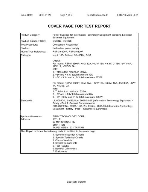
Product Category: Power Supplies <strong>for</strong> In<strong>for</strong>mation Technology Equipment Including Electrical<br />
Business Equipment<br />
Product Category CCN: QQGQ2, QQGQ8<br />
Test Procedure: Component Recognition<br />
Product: Redundant power supply<br />
Model/Type Reference: RSPM-6300P, RSPM-6320P<br />
Rating(s): Input: 100- 240Vac, 50- 60Hz, 6- 3A<br />
Output:<br />
For model: RSPM-6300P, +5V/ 32A, +12V/ 16A, +3.3V/ 0- 16A, -5V/ 0.5A, -<br />
12V/ 1A, +5VSB/ 2A.<br />
note:<br />
1. Total output maximum 300W.<br />
2. +5V and +3.3V total maximum 32A.<br />
3. +5V, +3.3V and +12V total maximum 283W.<br />
For model: RSPM-6320P, +5V/ 32A, +12V/ 16A, +3.3V/ 16A, -5V/ 0.5A, -12V/<br />
1A, +5VSB/ 2A.<br />
note:<br />
1. Total output maximum 320W.<br />
2. +5V and +3.3V total maximum 32A.<br />
3. +5V, +3.3V and +12V total maximum 303 W.<br />
Standards: UL 60950-1, 2nd Edition, 2007-03-27 (In<strong>for</strong>mation Technology Equipment -<br />
Safety - Part 1: General Requirements)<br />
CSA C22.2 No. 60950-1-07, 2nd Edition, 2007-03 (In<strong>for</strong>mation Technology<br />
Equipment - Safety - Part 1: General Requirements)<br />
Applicant Name and<br />
Address:<br />
ZIPPY TECHNOLOGY CORP<br />
10TH FL<br />
50 MIN CHYUAN RD<br />
SHIN-TIEN<br />
TAIPEI HSIEN 231 TAIWAN<br />
This Report includes the following parts, in addition to this <strong>cover</strong> <strong>page</strong>:<br />
1. Specific Inspection Criteria<br />
2. Specific Technical Criteria<br />
3. Clause Verdicts<br />
4. Critical Components<br />
5. Test Results<br />
6. National Differences<br />
7. Enclosures<br />
Copyright © 2010
Issue Date: 2010-01-29 Page 2 of 2 Report Reference # E143756-A26-UL-2<br />
This is to certify that representative samples of the products <strong>cover</strong>ed by this Test Report have been investigated in accordance with the<br />
above referenced Standards. The products have been found to comply with the requirements <strong>cover</strong>ing the category and the products are<br />
judged to be eligible <strong>for</strong> Follow -Up Service under the indicated Test Procedure. The manufacturer is authorized to use the UL Mark on<br />
such products which comply with this Test Report and any other applicable requirements of Underwriters Laboratories Inc. ('UL') in<br />
accordance with the Follow -Up Service Agreement. Only those products which properly bear the UL Mark are considered as being<br />
<strong>cover</strong>ed by UL's Follow -Up Service under the indicated Test Procedure.<br />
The applicant is authorized to reproduce the referenced Test Report provided it is reproduced in its entirety.<br />
UL authorizes the applicant to reproduce the la<strong>test</strong> <strong>page</strong>s of the referenced Test Report consisting of the first <strong>page</strong> of the Specific<br />
Technical Criteria through to the end of the Conditions of Acceptability.<br />
Any in<strong>for</strong>mation and documentation provided to you involving UL Mark services are provided on behalf of Underwriters Laboratories<br />
Inc(ULI) or any authorized license of ULI.<br />
Test Report By: Reviewed By:<br />
Rex Lin Wim Liang<br />
Associate Project Engineer Project Engineer<br />
Underwriters Laboratories Taiwan Co., Ltd. UL-CCIC Company Limited<br />
Copyright © 2010
Issue Date: 2010-01-29 Page 1 of 69 Report Reference # E143756-A26-UL-2<br />
SPECIFIC INSPECTION CRITERIA<br />
BA1.0 Special Instructions to UL Representative<br />
BA1.1 Inspect the trans<strong>for</strong>mer(s) listed in BD1.1 per AA1.1-(C). When the <strong>test</strong>s are conducted at other<br />
location, inspect <strong>test</strong> record and specification sheet provided by the component manufacturer.<br />
Verify the specification sheet indicates 100% routine <strong>test</strong> specified in BD1.1 be conducted at the<br />
component manufacturer.<br />
BB1.0 Supporting Documentation<br />
BB1.1 The following documents located at the beginning of this Procedure supplement the requirements<br />
of this Test Report:<br />
A. Authorization - The Authorization <strong>page</strong> may include additional Factory Identification Code<br />
markings.<br />
B. Generic Inspection Instructions -<br />
i. Part AC details important in<strong>for</strong>mation which may be applicable to products <strong>cover</strong>ed by this<br />
Procedure. Products described in this Test Report must comply with any applicable items<br />
listed unless otherwise stated in the body of this Test Report.<br />
ii. Part AE details any requirements which may be applicable to all products <strong>cover</strong>ed by this<br />
Procedure. Products described in this Test Report must comply with any applicable items<br />
listed unless otherwise stated in the body of each Test Report.<br />
iii. Part AF details the requirements <strong>for</strong> the UL Certification Mark which is not controlled by the<br />
technical standard used to investigate these products. Products are permitted to bear only<br />
the Certification Mark(s) corresponding to the countries <strong>for</strong> which it is certified, as indicated<br />
in each Test Report.<br />
BC1.0 Markings and instructions<br />
BC1.1 The following markings and instructions are provided as indicated.<br />
BC1.2 All clause references are from UL 60950-1, 2nd Edition, 2007-03-27 (In<strong>for</strong>mation Technology<br />
Equipment - Safety - Part 1: General Requirements).<br />
Standard<br />
Clause<br />
Clause Title Marking or Instruction Details<br />
1.7.1 Power rating -<br />
Ratings<br />
Power rating -<br />
Company<br />
identification<br />
Power rating -<br />
Model<br />
Ratings (voltage, frequency/dc, current)<br />
Listee's or Recognized company's name, Trade Name, Trademark or File<br />
Number<br />
Model Number<br />
1.7.6 Fuses - Rating Rated current and voltage and type located on or adjacent to fuse or<br />
fuseholder.<br />
1.7.8.3 Symbols - On/Off All other controls to be marked with symbol <strong>for</strong> "ON" (60417-2-IEC-5007)<br />
TRF No. IECEN60950_1C Underwriters Laboratories Inc.
Issue Date: 2010-01-29 Page 2 of 69 Report Reference # E143756-A26-UL-2<br />
switch<br />
BD1.0 Production-Line Testing Requirements<br />
and symbol <strong>for</strong> "OFF" (60417-2-IEC-5008)<br />
BD1.1 Electric Strength Test Special Constructions - Refer to Generic Inspection Instructions, Part AC <strong>for</strong><br />
further in<strong>for</strong>mation.<br />
Model Component Removable Parts Test probe location<br />
TRF No. IECEN60950_1C Underwriters Laboratories Inc.<br />
Test<br />
Potential<br />
V<br />
rms V dc<br />
All Models T3, T4 -- Pri - Sec 3000 424<br />
2<br />
BD1.2 Earthing Continuity Test Exemptions - This<br />
<strong>test</strong> is not required <strong>for</strong> the following models:<br />
BD1.3 Electric Strength Test Exemptions - This <strong>test</strong><br />
is not required <strong>for</strong> the following models:<br />
BD1.4 Electric Strength Test Component<br />
Exemptions - The following solid-state<br />
components may disconnected from the<br />
remainder of the circuitry during the<br />
per<strong>for</strong>mance of this <strong>test</strong>:<br />
All Models<br />
All Models<br />
N/A<br />
BE1.0 Sample and Test Specifics <strong>for</strong> Follow-Up Tests at UL<br />
BE1.1<br />
N/A<br />
Model Component Material Test Sample(s)<br />
Test<br />
Time, s<br />
1<br />
Test<br />
Specifics
Issue Date: 2010-01-29 Page 3 of 69 Report Reference # E143756-A26-UL-2<br />
SPECIFIC TECHNICAL CRITERIA<br />
UL 60950-1:2005 (2nd Edition)<br />
In<strong>for</strong>mation technology equipment - Safety -<br />
Part 1: General requirements<br />
Report Reference No ..................... : E143756-A26-UL-2<br />
Compiled by ................................. : Rex Lin<br />
Reviewed by ................................. : Wim Liang<br />
Date of issue ................................ : 2010-01-29<br />
Standards ..................................... : UL 60950-1, 2nd Edition, 2007-03-27 (In<strong>for</strong>mation Technology<br />
Equipment - Safety - Part 1: General Requirements)<br />
CSA C22.2 No. 60950-1-07, 2nd Edition, 2007-03 (In<strong>for</strong>mation<br />
Technology Equipment - Safety - Part 1: General Requirements)<br />
Test procedure .............................. : Component Recognition<br />
Non-standard <strong>test</strong> method ............. : N/A<br />
Test item description .................... : Redundant power supply<br />
Trademark .................................... : None<br />
Model and/or type reference .......... : RSPM-6300P, RSPM-6320P<br />
Rating(s) ...................................... : Input: 100- 240Vac, 50- 60Hz, 6- 3A<br />
TRF No. IECEN60950_1C Underwriters Laboratories Inc.<br />
Output:<br />
For model: RSPM-6300P, +5V/ 32A, +12V/ 16A, +3.3V/ 0- 16A, -5V/<br />
0.5A, -12V/ 1A, +5VSB/ 2A.<br />
note:<br />
1. Total output maximum 300W.<br />
2. +5V and +3.3V total maximum 32A.<br />
3. +5V, +3.3V and +12V total maximum 283W.<br />
For model: RSPM-6320P, +5V/ 32A, +12V/ 16A, +3.3V/ 16A, -5V/<br />
0.5A, -12V/ 1A, +5VSB/ 2A.<br />
note:<br />
1. Total output maximum 320W.<br />
2. +5V and +3.3V total maximum 32A.<br />
3. +5V, +3.3V and +12V total maximum 303 W.
Issue Date: 2010-01-29 Page 4 of 69 Report Reference # E143756-A26-UL-2<br />
Particulars: <strong>test</strong> item vs. <strong>test</strong> requirements<br />
Equipment mobility ................................................: <strong>for</strong> building-in<br />
Connection to the mains ........................................: pluggable A<br />
Operating condition ...............................................: continuous<br />
Over voltage category ...........................................: OVC II<br />
Mains supply tolerance (%) ....................................: +10%, -10%<br />
Tested <strong>for</strong> IT power systems ..................................: No<br />
IT <strong>test</strong>ing, phase-phase voltage (V) ........................: N/A<br />
Class of equipment ...............................................: Class I (earthed)<br />
Mass of equipment (kg) .........................................: 2.6Kg (Max)<br />
Pollution degree ....................................................: PD 2<br />
IP protection class .................................................: IP X0<br />
Possible <strong>test</strong> case verdicts:<br />
- <strong>test</strong> case does not apply to the <strong>test</strong> object .............: N / A<br />
- <strong>test</strong> object does meet the requirement ..................: Pass<br />
- <strong>test</strong> object does not meet the requirement ............: Fail (acceptable only if a corresponding, less stringent<br />
national requirement is "Pass")<br />
General remarks:<br />
- "(see Enclosure #)" refers to additional in<strong>for</strong>mation appended to the Test Report<br />
- "(see appended table)" refers to a table appended to the Test Report<br />
- Throughout the Test Report a point is used as the decimal separator<br />
TRF No. IECEN60950_1C Underwriters Laboratories Inc.
Issue Date: 2010-01-29 Page 5 of 69 Report Reference # E143756-A26-UL-2<br />
GENERAL PRODUCT INFORMATION:<br />
CA1.0 Report Summary<br />
CA1.1 N/A<br />
CB1.0 Product Description<br />
CB1.1 The product is an enclosed switch mode power supply intended <strong>for</strong> factory installation as a<br />
component of end product In<strong>for</strong>mation Technology Equipment.<br />
CC1.0 Model Differences<br />
CC1.1 All models are identical except <strong>for</strong> output ratings, model designation and as described in the<br />
<strong>report</strong>.<br />
CD1.0 Additional In<strong>for</strong>mation<br />
CD1.1 Reissue 2:<br />
1. Upgrade Standard 69050-1 2nd Edition;<br />
2. Alternate Varistors source with CCN: VZCA2.<br />
CE1.0 Technical Considerations<br />
CE1.2 The product was submitted and evaluated <strong>for</strong> use at the maximum ambient temperature (Tma)<br />
permitted by the manufacturer’s specification of: 50°C<br />
CE1.3 The means of connection to the mains supply is: Detachable power cord or Pluggable A<br />
CE1.4 The product is intended <strong>for</strong> use on the following power systems: TN<br />
CE1.5 The equipment disconnect device is considered to be: Appliance inlet<br />
CE1.13 The following are available from the Applicant upon request: Specific data sheets <strong>for</strong> LED<br />
indicators that are class I and operate at wavelength in the 400-710 nm range.<br />
CF1.0 Engineering Conditions of Acceptability<br />
CF1.1 For use only in or with complete equipment where the acceptability of the combination is<br />
determined by Underwriters Laboratories Inc.<br />
When installed in an end-product, consideration must be given to the following:<br />
CF1.3 The end-product Electric Strength Test is to be based upon a maximum working voltage of:<br />
Primary-Earthed Dead Metal: 416 Vrms, 800 Vpk, Primary-SELV: 423Vrms, 820 Vpk<br />
CF1.5 The following secondary output circuits are SELV: All outputs<br />
CF1.6 The following secondary output circuits are at hazardous energy levels: Output +5V and +12V<br />
CF1.7 The following secondary output circuits are at non-hazardous energy levels: All outputs except<br />
+5V and +12V.<br />
CF1.10 The following output terminals were referenced to earth during per<strong>for</strong>mance <strong>test</strong>ing: Output (-)<br />
TRF No. IECEN60950_1C Underwriters Laboratories Inc.
Issue Date: 2010-01-29 Page 6 of 69 Report Reference # E143756-A26-UL-2<br />
CF1.11 The power supply terminals and/or connectors are: Suitable <strong>for</strong> factory wiring only<br />
CF1.12 The maximum investigated branch circuit rating is: 20 A<br />
CF1.13 The investigated Pollution Degree is: 2<br />
CF1.15 Proper bonding to the end-product main protective earthing termination is: Required<br />
CF1.16 An investigation of the protective bonding terminals has: Been conducted<br />
CF1.18 The following magnetic devices (e.g. trans<strong>for</strong>mers or inductor) are provided with an OBJY2<br />
insulation system with the indicated rating greater than Class A (105°C): T3, T4(Class B)<br />
CF1.19 The following end-product enclosures are required: Electrical, Fire<br />
CF1.23 The equipment is suitable <strong>for</strong> direct connection to: AC mains supply<br />
TRF No. IECEN60950_1C Underwriters Laboratories Inc.
Issue Date: 2010-01-29 Page 7 of 69 Report Reference # E143756-A26-UL-2<br />
IEC 60950-1:2005<br />
Clause Requirement + Test Result - Remark Verdict<br />
1 GENERAL Pass<br />
1.5 Components Pass<br />
1.5.1 General Pass<br />
Comply with IEC 60950 or relevant component<br />
standard<br />
TRF No. IECEN60950_1C Underwriters Laboratories Inc.<br />
See table 1.5.1 Pass<br />
1.5.2 Evaluation and <strong>test</strong>ing of components Components certified to IEC<br />
harmonized standard and<br />
checked <strong>for</strong> correct application<br />
1.5.3 Thermal controls N/A<br />
1.5.4 Trans<strong>for</strong>mers Trans<strong>for</strong>mer used is suitable<br />
<strong>for</strong> its intended application and<br />
complies with the relevant<br />
requirements of the standard<br />
and particularly Annex C.<br />
1.5.5 Interconnecting cables Interconnecting cables comply<br />
with the relevant requirements<br />
of this standard.<br />
1.5.6 Capacitors bridging insulation Line-to-Line capacitors are<br />
subclass X1 or X2. Primaryto-earth<br />
capacitors are<br />
subclass Y1 or Y2.<br />
1.5.7 Resistors bridging insulation Pass<br />
1.5.7.1 Resistors bridging functional, basic or<br />
supplementary insulation<br />
1.5.7.2 Resistors bridging double or rein<strong>for</strong>ced insulation<br />
between a.c. mains and other circuits<br />
1.5.7.3 Resistors bridging double or rein<strong>for</strong>ced insulation<br />
between a.c. mains and antenna or coaxial cable<br />
1.5.7.4 Accessible parts N/A<br />
1.5.8 Components in equipment <strong>for</strong> IT power systems N/A<br />
1.5.9 Surge suppressors Pass<br />
1.5.9.1 General Pass<br />
1.5.9.2 Protection of VDRs Pass<br />
1.5.9.3 Bridging of functional insulation by a VDR Pass<br />
1.5.9.4 Bridging of basic insulation by a VDR N/A<br />
1.5.9.5 Bridging of supplementary, double or rein<strong>for</strong>ced<br />
insulation by a VDR<br />
Pass<br />
Pass<br />
Pass<br />
Pass<br />
Pass<br />
Pass<br />
N/A<br />
N/A
Issue Date: 2010-01-29 Page 8 of 69 Report Reference # E143756-A26-UL-2<br />
IEC 60950-1:2005<br />
Clause Requirement + Test Result - Remark Verdict<br />
1.6 Power interface Pass<br />
1.6.1 AC power distribution systems Pass<br />
1.6.2 Input current This equipment is the<br />
operation with the max.<br />
specified DC-load. Results see<br />
appended table.<br />
1.6.3 Voltage limit of hand-held equipment N/A<br />
1.6.4 Neutral conductor Neutral is insulated from earth<br />
with basic insulation.<br />
TRF No. IECEN60950_1C Underwriters Laboratories Inc.<br />
Pass<br />
Pass
Issue Date: 2010-01-29 Page 9 of 69 Report Reference # E143756-A26-UL-2<br />
IEC 60950-1:2005<br />
Clause Requirement + Test Result - Remark Verdict<br />
1.7 Marking and instructions Pass<br />
1.7.1 Power rating Pass<br />
Rated voltage(s) or voltage range(s) (V).............. : See "SPECIFIC TECHNICAL<br />
CRITERIA" <strong>for</strong> detail.<br />
Symbol <strong>for</strong> nature of supply, <strong>for</strong> d.c. only............. : N/A<br />
Rated frequency or rated frequency range (Hz)... : See "SPECIFIC TECHNICAL<br />
CRITERIA" <strong>for</strong> detail.<br />
Rated current (mA or A)..................................... : See "SPECIFIC TECHNICAL<br />
CRITERIA" <strong>for</strong> detail.<br />
Manufacturer's name or trademark or identification<br />
mark ................................................................. :<br />
TRF No. IECEN60950_1C Underwriters Laboratories Inc.<br />
See "SPECIFIC TECHNICAL<br />
CRITERIA" <strong>for</strong> detail.<br />
Model identification or type reference.................. : See "SPECIFIC TECHNICAL<br />
CRITERIA" <strong>for</strong> detail.<br />
Symbol <strong>for</strong> Class II equipment only ..................... : N/A<br />
Other markings and symbols .............................. : The additional marking does<br />
not give rise to<br />
misunderstandings.<br />
1.7.2 Safety instructions and marking Installation instruction with<br />
directions to maintain the<br />
requirements of IEC 60950<br />
during the installation into the<br />
end system. Included are<br />
directions regarding the<br />
maximum ambient<br />
temperature and electrical<br />
rating of the equipment.<br />
1.7.2.1 General Pass<br />
1.7.2.2 Disconnect devices N/A<br />
1.7.2.3 Overcurrent protective device N/A<br />
1.7.2.4 IT Power distribution systems N/A<br />
1.7.2.5 Operator access with a tool N/A<br />
1.7.2.6 Ozone N/A<br />
1.7.3 Short duty cycles N/A<br />
1.7.4 Supply voltage adjustment ................................. : N/A<br />
Method and means of adjustment; reference to<br />
installation instructions ....................................... :<br />
1.7.5 Power outlets on the equipment ......................... : N/A<br />
1.7.6 Fuse identification (marking, special fusing<br />
characteristics, cross-reference)......................... :<br />
Fuse marking on PCB near<br />
fuse or provided in service<br />
Pass<br />
Pass<br />
Pass<br />
Pass<br />
Pass<br />
Pass<br />
Pass<br />
N/A<br />
Pass
Issue Date: 2010-01-29 Page 10 of 69 Report Reference # E143756-A26-UL-2<br />
IEC 60950-1:2005<br />
Clause Requirement + Test Result - Remark Verdict<br />
TRF No. IECEN60950_1C Underwriters Laboratories Inc.<br />
documentation.<br />
1.7.7 Wiring terminals Pass<br />
1.7.7.1 Protective earthing and bonding terminals........... : The earth terminal is marked<br />
with the standard earth symbol<br />
(60417-2-IEC-5017) near the<br />
terminal.<br />
1.7.7.2 Terminal <strong>for</strong> a.c. mains supply conductors Not permanently connected<br />
unit.<br />
1.7.7.3 Terminals <strong>for</strong> d.c. mains supply conductors N/A<br />
1.7.8 Controls and indicators See below. Pass<br />
1.7.8.1 Identification, location and marking ..................... : An LED provided <strong>for</strong> indicating<br />
power ON mode.<br />
1.7.8.2 Colours ............................................................. : A green LED is illuminated<br />
when the unit is operating.<br />
A red LED is illuminated when<br />
one board is not operating.<br />
1.7.8.3 Symbols according to IEC 60417 ........................ : The mains switch is marked<br />
with the symbols: "0" and "I"<br />
(60417-1-IEC-5007 and IEC-<br />
5008).<br />
1.7.8.4 Markings using figures ....................................... : N/A<br />
1.7.9 Isolation of multiple power sources ..................... : N/A<br />
1.7.10 Thermostats and other regulating devices ........... : N/A<br />
1.7.11 Durability All markings provided on UL<br />
Recognized Component labels<br />
suitable <strong>for</strong> surface they are<br />
applied upon and meet the<br />
durability <strong>test</strong>.<br />
1.7.12 Removable parts N/A<br />
1.7.13 Replaceable batteries ........................................ : N/A<br />
Language(s)...................................................... : -<br />
1.7.14 Equipment <strong>for</strong> restricted access locations............ : To be determined in the end<br />
product.<br />
Pass<br />
N/A<br />
Pass<br />
Pass<br />
Pass<br />
Pass<br />
N/A
Issue Date: 2010-01-29 Page 11 of 69 Report Reference # E143756-A26-UL-2<br />
IEC 60950-1:2005<br />
Clause Requirement + Test Result - Remark Verdict<br />
2 PROTECTION FROM HAZARDS Pass<br />
2.1 Protection from electric shock and energy hazards Pass<br />
2.1.1 Protection in operator access areas Should be investigated in the<br />
final system assembly.<br />
2.1.1.1 Access to energized parts Equipment <strong>for</strong> building-in.<br />
Compliance with the<br />
requirements of this clause<br />
shall be evaluated during the<br />
approval of the final system.<br />
Test by inspection ............................................. : N/A<br />
Test with <strong>test</strong> finger (Figure 2A).......................... : N/A<br />
Test with <strong>test</strong> pin (Figure 2B).............................. : N/A<br />
Test with <strong>test</strong> probe (Figure 2C) ......................... : N/A<br />
2.1.1.2 Battery compartments N/A<br />
2.1.1.3 Access to ELV wiring N/A<br />
Working voltage (Vpeak or Vrms); minimum<br />
distance through insulation (mm)........................ :<br />
2.1.1.4 Access to hazardous voltage circuit wiring Should be investigated in the<br />
final system assembly.<br />
2.1.1.5 Energy hazards ................................................. : The output energy level<br />
exceeds 240VA. Compliance<br />
is to be evaluated <strong>for</strong> the final<br />
system.<br />
2.1.1.6 Manual controls N/A<br />
2.1.1.7 Discharge of capacitors in equipment No risk of electric shock. Pass<br />
Measured voltage (V); time-constant (s).............. : Fuse In, Switch both on:<br />
Maximum 376Vpk decay to<br />
139.12 Vpk (37% of its original<br />
value) at 0.318 sec within 1.0<br />
second.<br />
TRF No. IECEN60950_1C Underwriters Laboratories Inc.<br />
Fuse In, Switch one on, one<br />
off: Maximum 376Vpk decay to<br />
139.12Vpk (37% of its original<br />
value) at 0.524 sec within 1.0<br />
second.<br />
Fuse In, Switch both off:<br />
Maximum 368Vpk decay to<br />
136.16Vpk (37% of its original<br />
value) at 0.984 sec within 1.0<br />
second.<br />
Pass<br />
N/A<br />
-<br />
N/A<br />
N/A<br />
-
Issue Date: 2010-01-29 Page 12 of 69 Report Reference # E143756-A26-UL-2<br />
IEC 60950-1:2005<br />
Clause Requirement + Test Result - Remark Verdict<br />
2.1.1.8 Energy hazards - d.c. mains supply N/A<br />
a) Capacitor connected to the d.c. mains supply .. : N/A<br />
b) Internal battery connected to the mains supply : N/A<br />
2.1.1.9 Audio amplifiers ................................................. : N/A<br />
2.1.2 Protection in service access areas Equipment <strong>for</strong> building-in.<br />
Compliance shall be<br />
investigated in the final system<br />
assembly.<br />
2.1.3 Protection in restricted access locations Equipment <strong>for</strong> building-in. N/A<br />
2.2 SELV circuits Pass<br />
2.2.1 General requirements SELV levels are maintained<br />
after single fault condition.<br />
2.2.2 Voltages under normal conditions (V).................. : All accessible voltages are<br />
less than 42.4 Vp or 60 V dc<br />
and are classified as SELV.<br />
2.2.3 Voltages under fault conditions (V) ..................... : Under fault conditions.<br />
voltages never exceed 71V<br />
peak and 120Vdc and do not<br />
exceed 42.2V peak or 60V dc<br />
<strong>for</strong> more than 0.2 sec.<br />
2.2.4 Connection of SELV circuits to other circuits ....... : SELV circuits are only<br />
connected to other secondary<br />
circuits. SELV circuit and all<br />
interconnected circuits<br />
separated from primary by<br />
Rein<strong>for</strong>ced insulation. The<br />
SELV circuit does not exceed<br />
the SELV limits under normal<br />
and fault conditions.<br />
TRF No. IECEN60950_1C Underwriters Laboratories Inc.<br />
N/A<br />
Pass<br />
Pass<br />
Pass<br />
Pass
Issue Date: 2010-01-29 Page 13 of 69 Report Reference # E143756-A26-UL-2<br />
IEC 60950-1:2005<br />
Clause Requirement + Test Result - Remark Verdict<br />
2.3 TNV circuits N/A<br />
2.3.1 Limits No TNV circuit. N/A<br />
Type of TNV circuits .......................................... : -<br />
2.3.2 Separation from other circuits and from accessible<br />
parts<br />
2.3.2.1 General requirements N/A<br />
2.3.2.2 Protection by basic insulation N/A<br />
2.3.2.3 Protection by earthing N/A<br />
2.3.2.4 Protection by other constructions ........................ : N/A<br />
2.3.3 Separation from hazardous voltages N/A<br />
Insulation employed........................................... : -<br />
2.3.4 Connection of TNV circuits to other circuits N/A<br />
Insulation employed........................................... : -<br />
2.3.5 Test <strong>for</strong> operating voltages generated externally N/A<br />
2.4 Limited current circuits N/A<br />
2.4.1 General requirements N/A<br />
2.4.2 Limit values N/A<br />
Frequency (Hz) ................................................. : -<br />
Measured current (mA) ...................................... : -<br />
Measured voltage (V) ........................................ : -<br />
Measured circuit capacitance (nF or uF) ............. : -<br />
2.4.3 Connection of limited current circuits to other<br />
circuits<br />
TRF No. IECEN60950_1C Underwriters Laboratories Inc.<br />
N/A<br />
N/A
Issue Date: 2010-01-29 Page 14 of 69 Report Reference # E143756-A26-UL-2<br />
IEC 60950-1:2005<br />
Clause Requirement + Test Result - Remark Verdict<br />
2.5 Limited power sources N/A<br />
a) Inherently limited output N/A<br />
b) Impedance limited output N/A<br />
c) Regulating network limited output under normal<br />
operating and single fault condition<br />
d) Overcurrent protective device limited output N/A<br />
Max. output voltage (V), max. output current (A),<br />
max. apparent power (VA) ................................. :<br />
Current rating of overcurrent protective device (A): -<br />
TRF No. IECEN60950_1C Underwriters Laboratories Inc.<br />
N/A<br />
-
Issue Date: 2010-01-29 Page 15 of 69 Report Reference # E143756-A26-UL-2<br />
IEC 60950-1:2005<br />
Clause Requirement + Test Result - Remark Verdict<br />
2.6 Provisions <strong>for</strong> earthing and bonding Pass<br />
2.6.1 Protective earthing Accessible parts (chassis) are<br />
earthed.<br />
2.6.2 Functional earthing SELV circuits. Pass<br />
2.6.3 Protective earthing and protective bonding<br />
conductors<br />
TRF No. IECEN60950_1C Underwriters Laboratories Inc.<br />
Pass<br />
Appliance Inlet used. Pass<br />
2.6.3.1 General Pass<br />
2.6.3.2 Size of protective earthing conductors No power cord provided. N/A<br />
Rated current (A), cross-sectional area (mm²),<br />
AWG ................................................................ :<br />
2.6.3.3 Size of protective bonding conductors Protective bonding evaluated<br />
based on 2.6.3.4.<br />
Rated current (A), cross-sectional area mm²), AWG<br />
........................................................................ :<br />
2.6.3.4 Resistance of earthing conductors and their<br />
terminations; resistance (ohm), voltage drop (V),<br />
<strong>test</strong> current (A), duration (min)............................ :<br />
Earth Pin of terminal to<br />
Chassis<br />
1: Test Current=25A,<br />
resistance=16.2m ohm.<br />
2: Test Current=40A,<br />
resistance=14.4m ohm.<br />
2.6.3.5 Colour of insulation ............................................ : Green / Yellow wire from AC<br />
inlet to chassis. The wire is<br />
reliably fixed to the chassis<br />
with star washer and screw.<br />
2.6.4 Terminals Appliance inlet used. Pass<br />
2.6.4.1 General Pass<br />
2.6.4.2 Protective earthing and bonding terminals Pass<br />
Rated current (A), type, nominal thread diameter<br />
(mm)................................................................. :<br />
2.6.4.3 Separation of the protective earthing conductor<br />
from protective bonding conductors<br />
Complies with the <strong>test</strong> of<br />
2.6.3.4<br />
Detachable power cord.<br />
Power Cord not provided.<br />
Appliance inlet has earthing<br />
terminal.<br />
2.6.5 Integrity of protective earthing Pass<br />
2.6.5.1 Interconnection of equipment Equipment contains a<br />
protective bonding conductor<br />
to maintain continuity of<br />
protective earthing circuits to<br />
other equipment through a<br />
standard outlet that complies<br />
with IEC 60320.<br />
-<br />
N/A<br />
-<br />
Pass<br />
Pass<br />
-<br />
N/A<br />
Pass
Issue Date: 2010-01-29 Page 16 of 69 Report Reference # E143756-A26-UL-2<br />
IEC 60950-1:2005<br />
Clause Requirement + Test Result - Remark Verdict<br />
2.6.5.2 Components in protective earthing conductors and<br />
protective bonding conductors<br />
TRF No. IECEN60950_1C Underwriters Laboratories Inc.<br />
No switch or overcurrent<br />
protective device in protective<br />
earthing or bonding conductor.<br />
2.6.5.3 Disconnection of protective earth Disconnection of the protective<br />
earth at one assembly<br />
removes connection of<br />
HAZARDOUS VOLTAGES<br />
from the other assemblies at<br />
the same time.<br />
2.6.5.4 Parts that can be removed by an operator Protective earth required<br />
makes earlier and breaks later<br />
than the supply connectors.<br />
2.6.5.5 Parts removed during servicing Connections to protective<br />
earthing can be removed<br />
unless hazardous voltage is<br />
removed from the part<br />
simultaneously.<br />
2.6.5.6 Corrosion resistance No risk of corrosion. Complies<br />
with Annex J.<br />
2.6.5.7 Screws <strong>for</strong> protective bonding Metal thickness at least twice<br />
the pitch of the screw.<br />
At least two screws used.<br />
2.6.5.8 Reliance on telecommunication network or cable<br />
distribution system<br />
Pass<br />
Pass<br />
Pass<br />
Pass<br />
Pass<br />
Pass<br />
No TNV. N/A
Issue Date: 2010-01-29 Page 17 of 69 Report Reference # E143756-A26-UL-2<br />
IEC 60950-1:2005<br />
Clause Requirement + Test Result - Remark Verdict<br />
2.7 Overcurrent and earth fault protection in primary circuits Pass<br />
2.7.1 Basic requirements Protection provided as part of<br />
the building installation.<br />
Instructions when protection relies on building<br />
installation<br />
2.7.2 Faults not <strong>cover</strong>ed in 5.3.7 Protection from faults not<br />
<strong>cover</strong>ed in 5.3 are provided by<br />
installation.<br />
2.7.3 Short-circuit backup protection The equipment is pluggable<br />
Type A.<br />
Building installation is<br />
considered as providing shortcircuit<br />
backup protection.<br />
2.7.4 Number and location of protective devices .......... : One protective device in the<br />
"LIVE" phase.<br />
2.7.5 Protection by several devices Only one protective device is<br />
provided.<br />
2.7.6 Warning to service personnel ............................. : N/A<br />
2.8 Safety interlocks N/A<br />
2.8.1 General principles N/A<br />
2.8.2 Protection requirements N/A<br />
2.8.3 Inadvertent reactivation N/A<br />
2.8.4 Fail-safe operation N/A<br />
2.8.5 Moving parts N/A<br />
2.8.6 Overriding N/A<br />
2.8.7 Switches and relays N/A<br />
2.8.7.1 Contact gaps (mm) ............................................ : N/A<br />
2.8.7.2 Overload <strong>test</strong> N/A<br />
2.8.7.3 Endurance <strong>test</strong> N/A<br />
2.8.7.4 Electric strength <strong>test</strong> N/A<br />
2.8.8 Mechanical actuators N/A<br />
TRF No. IECEN60950_1C Underwriters Laboratories Inc.<br />
Pass<br />
N/A<br />
Pass<br />
N/A<br />
Pass<br />
N/A
Issue Date: 2010-01-29 Page 18 of 69 Report Reference # E143756-A26-UL-2<br />
IEC 60950-1:2005<br />
Clause Requirement + Test Result - Remark Verdict<br />
2.9 Electrical insulation Pass<br />
2.9.1 Properties of insulating materials Natural rubber, asbestos or<br />
hygroscopic materials are not<br />
used.<br />
2.9.2 Humidity conditioning 120 hours Pass<br />
Relative humidity (%), temperature (°C) .............. : 93% , 40°C -<br />
2.9.3 Grade of insulation The adequate levels of safety<br />
insulation are provided and<br />
maintained to comply with the<br />
requirements of this standard.<br />
2.9.4 Separation from hazardous voltages Pass<br />
Method(s) used ................................................. : Method 1 used -<br />
TRF No. IECEN60950_1C Underwriters Laboratories Inc.<br />
Pass<br />
Pass
Issue Date: 2010-01-29 Page 19 of 69 Report Reference # E143756-A26-UL-2<br />
IEC 60950-1:2005<br />
Clause Requirement + Test Result - Remark Verdict<br />
2.10 Clearances, cree<strong>page</strong> distances and distances through insulation Pass<br />
2.10.1 General See 2.10.3, 2.10.4, 2.10.5 Pass<br />
2.10.1.1 Frequency......................................................... : Less than 30 KHz Pass<br />
2.10.1.2 Pollution degrees ............................................... : 2 Pass<br />
2.10.1.3 Reduced values <strong>for</strong> functional insulation N/A<br />
2.10.1.4 Intervening unconnected conductive parts N/A<br />
2.10.1.5 Insulation with varying dimensions N/A<br />
2.10.1.6 Special separation requirements N/A<br />
2.10.1.7 Insulation in circuits generating starting pulses N/A<br />
2.10.2 Determination of working voltage Unit was connected to a 240V<br />
TN power system.<br />
2.10.2.1 General Pass<br />
2.10.2.2 RMS working voltage (see appended table 2.10.3<br />
and 2.10.4).<br />
2.10.2.3 Peak working voltage (see appended table 2.10.3<br />
and 2.10.4).<br />
2.10.3 Clearances (see appended table 2.10.3<br />
and 2.10.4).<br />
2.10.3.1 General Pass<br />
2.10.3.2 Mains transient voltages Overvoltage Category II; Mains<br />
transient voltage is 2500<br />
Vpeak<br />
TRF No. IECEN60950_1C Underwriters Laboratories Inc.<br />
Pass<br />
Pass<br />
Pass<br />
Pass<br />
Pass<br />
a) AC mains supply ........................................... : Less than 300 Vrms. Pass<br />
b) Earthed d.c. mains supplies............................ : N/A<br />
c) Unearthed d.c.. mains supplies ....................... : N/A<br />
d) Battery operation ........................................... : N/A<br />
2.10.3.3 Clearances in primary circuits See appended table 2.10.3<br />
and 2.10.4.<br />
2.10.3.4 Clearances in secondary circuits See 5.3.4. Pass<br />
2.10.3.5 Clearances in circuits having starting pulses N/A<br />
2.10.3.6 Transients from a.c. mains supply....................... : See 2.10.3.2 Pass<br />
2.10.3.7 Transients from d.c. mains supply....................... : N/A<br />
2.10.3.8 Transients from telecommunication networks and<br />
cable distribution systems .................................. :<br />
2.10.3.9 Measurement of transient voltage levels N/A<br />
Pass<br />
a) Transients from a mains supply N/A<br />
N/A
Issue Date: 2010-01-29 Page 20 of 69 Report Reference # E143756-A26-UL-2<br />
IEC 60950-1:2005<br />
Clause Requirement + Test Result - Remark Verdict<br />
For an a.c. mains supply .................................... : N/A<br />
For a d.c. mains supply ...................................... : N/A<br />
b) Transients from a telecommunication network N/A<br />
2.10.4 Cree<strong>page</strong> distances See TABLE: 2.10.3 and 2.10.4 Pass<br />
2.10.4.1 General Pass<br />
2.10.4.2 Material group and comparative tracking index Pass<br />
CTI <strong>test</strong>s ........................................................... : Material group IIIb; 100
Issue Date: 2010-01-29 Page 21 of 69 Report Reference # E143756-A26-UL-2<br />
IEC 60950-1:2005<br />
Clause Requirement + Test Result - Remark Verdict<br />
Two wires in contact inside wound component;<br />
angle between 45° and 90° ................................ :<br />
2.10.5.13 Wire with solvent-based enamel in wound<br />
components<br />
TRF No. IECEN60950_1C Underwriters Laboratories Inc.<br />
Physical separation in the <strong>for</strong>m<br />
of insulating sleeving provided<br />
to relieve mechanical stress at<br />
the crossover point.<br />
Electric strength <strong>test</strong> .......................................... : -<br />
Routine <strong>test</strong> N/A<br />
2.10.5.14 Additional insulation in wound components Thin sheet insulation provided<br />
<strong>for</strong> rein<strong>for</strong>ced insulation. See<br />
Sub clause 2.10.5.6.<br />
Working voltage ................................................ : (see appended table 2.10.3<br />
and 2.10.4)<br />
- Basic insulation not under stress ...................... : N/A<br />
Pass<br />
N/A<br />
Pass<br />
Pass<br />
- Supplementary, rein<strong>for</strong>ced insulation ................ : See Sub clause 2.10.5.6. Pass<br />
2.10.6 Construction of printed boards Pass<br />
2.10.6.1 Uncoated printed boards Pass<br />
2.10.6.2 Coated printed boards N/A<br />
2.10.6.3 Insulation between conductors on the same inner<br />
surface of a printed board<br />
2.10.6.4 Insulation between conductors on different layers<br />
of a printed board<br />
Distance through insulation N/A<br />
Number of insulation layers (pcs)........................ : N/A<br />
2.10.7 Component external terminations The mechanical arrangement<br />
and rigidity of the termination<br />
with an insulating coating is<br />
adequate.<br />
2.10.8 Tests on coated printed boards and coated<br />
components<br />
2.10.8.1 Sample preparation and preliminary inspection N/A<br />
2.10.8.2 Thermal conditioning N/A<br />
2.10.8.3 Electric strength <strong>test</strong> N/A<br />
2.10.8.4 Abrasion resistance <strong>test</strong> N/A<br />
2.10.9 Thermal cycling N/A<br />
2.10.10 Test <strong>for</strong> Pollution Degree 1 environment and<br />
insulating compound<br />
N/A<br />
N/A<br />
Pass<br />
N/A<br />
N/A
Issue Date: 2010-01-29 Page 22 of 69 Report Reference # E143756-A26-UL-2<br />
IEC 60950-1:2005<br />
Clause Requirement + Test Result - Remark Verdict<br />
2.10.11 Tests <strong>for</strong> semiconductor devices and cemented<br />
joints<br />
2.10.12 Enclosed and sealed parts N/A<br />
3 WIRING, CONNECTIONS AND SUPPLY Pass<br />
3.1 General Pass<br />
3.1.1 Current rating and overcurrent protection Pass<br />
3.1.2 Protection against mechanical damage The wires are routed away<br />
from sharp edges and parts<br />
which could damage<br />
insulation.<br />
3.1.3 Securing of internal wiring Pass<br />
3.1.4 Insulation of conductors The insulation of the individual<br />
conductors is suitable <strong>for</strong> the<br />
application and the working<br />
voltage.<br />
3.1.5 Beads and ceramic insulators N/A<br />
3.1.6 Screws <strong>for</strong> electrical contact pressure All electrical screw<br />
connections are by metal<br />
screw with more than 2<br />
threads into a metal plate.<br />
3.1.7 Insulating materials in electrical connections The equipment does not have<br />
any electrical connections that<br />
rely on insulating material <strong>for</strong><br />
adequate contact pressure.<br />
3.1.8 Self-tapping and spaced thread screws Thread-cutting or space thread<br />
screws are not used <strong>for</strong><br />
electrical connections.<br />
Machine screws only.<br />
3.1.9 Termination of conductors All conductors are reliable<br />
secured.<br />
10 N pull <strong>test</strong> Break away or pivot on its<br />
terminal is unlikely.<br />
3.1.10 Sleeving on wiring The sleeving used as<br />
supplementary insulation on<br />
internal wiring is retained by<br />
positive means.<br />
TRF No. IECEN60950_1C Underwriters Laboratories Inc.<br />
N/A<br />
Pass<br />
Pass<br />
Pass<br />
Pass<br />
Pass<br />
Pass<br />
Pass<br />
Pass
Issue Date: 2010-01-29 Page 23 of 69 Report Reference # E143756-A26-UL-2<br />
IEC 60950-1:2005<br />
Clause Requirement + Test Result - Remark Verdict<br />
3.2 Connection to mains supply Pass<br />
3.2.1 Means of connection Pass<br />
3.2.1.1 Connection to an a.c. mains supply The unit is provided with an<br />
appliance inlet.<br />
3.2.1.2 Connection to a d.c. mains supply N/A<br />
3.2.2 Multiple supply connections N/A<br />
3.2.3 Permanently connected equipment N/A<br />
Number of conductors, diameter of cable and<br />
conduits (mm) ................................................... :<br />
3.2.4 Appliance inlets The appliance inlet complies<br />
with IEC 60320.<br />
3.2.5 Power supply cords Cord not provided. N/A<br />
3.2.5.1 AC power supply cords N/A<br />
Type................................................................. : -<br />
Rated current (A), cross-sectional area (mm²),<br />
AWG ................................................................ :<br />
3.2.5.2 DC power supply cords N/A<br />
3.2.6 Cord anchorages and strain relief N/A<br />
Mass of equipment (kg), pull (N)......................... : -<br />
Longitudinal displacement (mm) ......................... : -<br />
3.2.7 Protection against mechanical damage N/A<br />
3.2.8 Cord guards N/A<br />
Diameter of minor dimension D (mm); <strong>test</strong> mass (g)<br />
........................................................................ :<br />
Radius of curvature of cord (mm)........................ : -<br />
3.2.9 Supply wiring space N/A<br />
TRF No. IECEN60950_1C Underwriters Laboratories Inc.<br />
Pass<br />
-<br />
Pass<br />
-<br />
-
Issue Date: 2010-01-29 Page 24 of 69 Report Reference # E143756-A26-UL-2<br />
IEC 60950-1:2005<br />
Clause Requirement + Test Result - Remark Verdict<br />
3.3 Wiring terminals <strong>for</strong> connection of external conductors N/A<br />
3.3.1 Wiring terminals N/A<br />
3.3.2 Connection of non-detachable power supply cords N/A<br />
3.3.3 Screw terminals N/A<br />
3.3.4 Conductor sizes to be connected N/A<br />
Rated current (A), cord/cable type, cross-sectional<br />
area (mm²) ........................................................ :<br />
3.3.5 Wiring terminal sizes N/A<br />
Rated current (A), type and nominal thread<br />
diameter (mm)................................................... :<br />
3.3.6 Wiring terminals design N/A<br />
3.3.7 Grouping of wiring terminals N/A<br />
3.3.8 Stranded wire N/A<br />
TRF No. IECEN60950_1C Underwriters Laboratories Inc.<br />
-<br />
-
Issue Date: 2010-01-29 Page 25 of 69 Report Reference # E143756-A26-UL-2<br />
IEC 60950-1:2005<br />
Clause Requirement + Test Result - Remark Verdict<br />
3.4 Disconnection from the mains supply Pass<br />
3.4.1 General requirement A disconnect device is<br />
provided to disconnect the<br />
equipment from the AC mains<br />
supply <strong>for</strong> servicing.<br />
3.4.2 Disconnect devices The equipment is provided<br />
with an appliance coupler.<br />
3.4.3 Permanently connected equipment Not permanently connected<br />
equipment.<br />
3.4.4 Parts which remain energized No accessible parts on the<br />
supply side of the disconnect<br />
device.<br />
3.4.5 Switches in flexible cords N/A<br />
3.4.6 Number of poles - single-phase and d.c. equipment Disconnect device disconnects<br />
all poles simultaneously.<br />
3.4.7 Number of poles - three-phase equipment The unit is single-phase<br />
equipment.<br />
3.4.8 Switches as disconnect devices N/A<br />
3.4.9 Plugs as disconnect devices N/A<br />
3.4.10 Interconnected equipment Interconnection to other<br />
devices by secondary output<br />
cable only.<br />
3.4.11 Multiple power sources The equipment only receives<br />
power from one source, and<br />
there<strong>for</strong>e only employs one<br />
disconnect device.<br />
3.5 Interconnection of equipment Pass<br />
3.5.1 General requirements SELV output circuits of power<br />
supply to be connected to<br />
other SELV circuits only.<br />
3.5.2 Types of interconnection circuits......................... : Interconnection circuits are<br />
SELV circuits.<br />
3.5.3 ELV circuits as interconnection circuits N/A<br />
3.5.4 Data ports <strong>for</strong> additional equipment N/A<br />
TRF No. IECEN60950_1C Underwriters Laboratories Inc.<br />
Pass<br />
Pass<br />
N/A<br />
N/A<br />
Pass<br />
N/A<br />
N/A<br />
N/A<br />
Pass<br />
Pass
Issue Date: 2010-01-29 Page 26 of 69 Report Reference # E143756-A26-UL-2<br />
IEC 60950-1:2005<br />
Clause Requirement + Test Result - Remark Verdict<br />
4 PHYSICAL REQUIREMENTS Pass<br />
4.1 Stability N/A<br />
Angle of 10° N/A<br />
Test <strong>for</strong>ce (N).................................................... : N/A<br />
4.2 Mechanical strength Pass<br />
4.2.1 General Equipment is <strong>for</strong> building-in.<br />
Compliance has to be<br />
evaluated when installed into<br />
the final system.<br />
4.2.2 Steady <strong>for</strong>ce <strong>test</strong>, 10 N 10N applied to components. Pass<br />
4.2.3 Steady <strong>for</strong>ce <strong>test</strong>, 30 N Equipment is <strong>for</strong> building-in.<br />
Compliance has to be<br />
evaluated when installed into<br />
the final system.<br />
4.2.4 Steady <strong>for</strong>ce <strong>test</strong>, 250 N No hazards as a result of the<br />
250 N <strong>test</strong> (only evaluated <strong>for</strong><br />
inlet side of enclosure).<br />
4.2.5 Impact <strong>test</strong> Equipment is <strong>for</strong> building-in. Pass<br />
Fall <strong>test</strong> N/A<br />
Swing <strong>test</strong> N/A<br />
4.2.6 Drop <strong>test</strong>; height (mm) ....................................... : N/A<br />
4.2.7 Stress relief <strong>test</strong> N/A<br />
4.2.8 Cathode ray tubes N/A<br />
Picture tube separately certified.......................... : N/A<br />
4.2.9 High pressure lamps N/A<br />
4.2.10 Wall or ceiling mounted equipment; <strong>for</strong>ce (N) ...... : N/A<br />
TRF No. IECEN60950_1C Underwriters Laboratories Inc.<br />
Pass<br />
N/A<br />
Pass
Issue Date: 2010-01-29 Page 27 of 69 Report Reference # E143756-A26-UL-2<br />
IEC 60950-1:2005<br />
Clause Requirement + Test Result - Remark Verdict<br />
4.3 Design and construction Pass<br />
4.3.1 Edges and corners All edges and corners are<br />
judged to be sufficiently well<br />
rounded so as not to constitute<br />
a hazard.<br />
4.3.2 Handles and manual controls; <strong>for</strong>ce (N) .............. : N/A<br />
4.3.3 Adjustable controls N/A<br />
4.3.4 Securing of parts No loosening of parts impairing<br />
cree<strong>page</strong> distances or<br />
clearances over<br />
supplementary or rein<strong>for</strong>ced<br />
insulation is likely to occur.<br />
4.3.5 Connection by plugs and sockets IEC 60083 or IEC 60320 type<br />
connectors not used <strong>for</strong> SELV<br />
circuits.<br />
4.3.6 Direct plug-in equipment N/A<br />
Torque .............................................................. : N/A<br />
Compliance with the relevant mains plug standard: N/A<br />
4.3.7 Heating elements in earthed equipment N/A<br />
4.3.8 Batteries N/A<br />
- Overcharging of a rechargeable battery N/A<br />
- Unintentional charging of a non-rechargeable<br />
battery<br />
- Reverse charging of a rechargeable battery N/A<br />
- Excessive discharging of any battery N/A<br />
4.3.9 Oil and grease N/A<br />
4.3.10 Dust, powders, liquids and gases N/A<br />
4.3.11 Containers <strong>for</strong> liquids or gases N/A<br />
4.3.12 Flammable liquids ............................................. : N/A<br />
Quantity of liquid (l)............................................ : N/A<br />
Flash point (°C) ................................................. : N/A<br />
4.3.13 Radiation Pass<br />
4.3.13.1 General See below. Pass<br />
4.3.13.2 Ionizing radiation N/A<br />
Measured radiation (pA/kg) ................................ : -<br />
Measured high-voltage (kV) ............................... : -<br />
Measured focus voltage (kV).............................. : -<br />
TRF No. IECEN60950_1C Underwriters Laboratories Inc.<br />
Pass<br />
Pass<br />
Pass<br />
N/A
Issue Date: 2010-01-29 Page 28 of 69 Report Reference # E143756-A26-UL-2<br />
IEC 60950-1:2005<br />
Clause Requirement + Test Result - Remark Verdict<br />
CRT markings ................................................... : -<br />
4.3.13.3 Effect of ultraviolet (UV) radiation on materials N/A<br />
Part, property, retention after <strong>test</strong>, flammability<br />
classification ..................................................... :<br />
4.3.13.4 Human exposure to ultraviolet (UV) radiation....... : N/A<br />
4.3.13.5 Laser (including LEDs) Pass<br />
Laser class........................................................ : LEDs are used <strong>for</strong> indicating<br />
purposes and assumed to be<br />
inherently Class 1 and<br />
operating in the 400 - 700 nm<br />
wavelength range.<br />
4.3.13.6 Other types ....................................................... : N/A<br />
4.4 Protection against hazardous moving parts Pass<br />
4.4.1 General Certified Fan in SELV circuit.<br />
(See table1.5.1)<br />
4.4.2 Protection in operator access areas .................... : Hazardous moving parts of<br />
equipment are adequately<br />
enclosed and guarded.<br />
4.4.3 Protection in restricted access locations .............. : N/A<br />
4.4.4 Protection in service access areas Pass<br />
TRF No. IECEN60950_1C Underwriters Laboratories Inc.<br />
N/A<br />
-<br />
Pass<br />
Pass
Issue Date: 2010-01-29 Page 29 of 69 Report Reference # E143756-A26-UL-2<br />
IEC 60950-1:2005<br />
Clause Requirement + Test Result - Remark Verdict<br />
4.5 Thermal requirements Pass<br />
4.5.1 General Pass<br />
4.5.2 Temperature <strong>test</strong>s See TABLE: 4.5 temperature<br />
rise measurements.<br />
Components working at high<br />
temperatures are shielded to<br />
prevent overheating of their<br />
surrounding materials.<br />
The equipment and its<br />
component parts did not attain<br />
excessive temperatures during<br />
normal operation.<br />
Normal load condition per Annex L ..................... : Operated in the most<br />
unfavorable way of operation<br />
given in the operating<br />
instructions until steady<br />
conditions established.<br />
4.5.3 Temperature limits <strong>for</strong> materials Pass<br />
4.5.4 Touch temperature limits Pass<br />
4.5.5 Resistance to abnormal heat .............................. : N/A<br />
TRF No. IECEN60950_1C Underwriters Laboratories Inc.<br />
Pass<br />
-
Issue Date: 2010-01-29 Page 30 of 69 Report Reference # E143756-A26-UL-2<br />
IEC 60950-1:2005<br />
Clause Requirement + Test Result - Remark Verdict<br />
4.6 Openings in enclosures N/A<br />
4.6.1 Top and side openings Mechanical enclosure<br />
evaluated.<br />
See critical component<br />
table/Power<br />
Module/Chassis construction.<br />
Unit intended <strong>for</strong> building-in.<br />
To be evaluated other<br />
enclosures in end product.<br />
Dimensions (mm) .............................................. : See table 1.5.1 -<br />
4.6.2 Bottoms of fire enclosures This equipment is <strong>for</strong> buildingin.<br />
Compliance shall be<br />
evaluated <strong>for</strong> the final system.<br />
Construction of the bottom, dimensions (mm) ...... : No openings -<br />
4.6.3 Doors or <strong>cover</strong>s in fire enclosures N/A<br />
4.6.4 Openings in transportable equipment N/A<br />
4.6.4.1 Constructional design measures N/A<br />
Dimensions (mm) .............................................. : -<br />
4.6.4.2 Evaluation measures <strong>for</strong> larger openings N/A<br />
4.6.4.3 Use of metallized parts N/A<br />
4.6.5 Adhesives <strong>for</strong> constructional purposes N/A<br />
Conditioning temperature (°C), time (weeks) ....... : -<br />
TRF No. IECEN60950_1C Underwriters Laboratories Inc.<br />
N/A<br />
N/A
Issue Date: 2010-01-29 Page 31 of 69 Report Reference # E143756-A26-UL-2<br />
IEC 60950-1:2005<br />
Clause Requirement + Test Result - Remark Verdict<br />
4.7 Resistance to fire Pass<br />
4.7.1 Reducing the risk of ignition and spread of flame Pass<br />
Method 1, selection and application of components<br />
wiring and materials<br />
Method 2, application of all of simulated fault<br />
condition <strong>test</strong>s<br />
TRF No. IECEN60950_1C Underwriters Laboratories Inc.<br />
Method 1: Selection and<br />
application of components and<br />
materials which minimize the<br />
possibility of ignition and<br />
spread of flame.<br />
4.7.2 Conditions <strong>for</strong> a fire enclosure For building-in, parts require a<br />
fire enclosure and shall be<br />
evaluated in final system.<br />
4.7.2.1 Parts requiring a fire enclosure N/A<br />
4.7.2.2 Parts not requiring a fire enclosure N/A<br />
4.7.3 Materials Pass<br />
4.7.3.1 General PCB rated V-1 or better. Pass<br />
4.7.3.2 Materials <strong>for</strong> fire enclosures This equipment is <strong>for</strong> buildingin.<br />
Compliance shall be<br />
evaluated <strong>for</strong> the final system.<br />
Product uses Metal.<br />
4.7.3.3 Materials <strong>for</strong> components and other parts outside<br />
fire enclosures<br />
4.7.3.4 Materials <strong>for</strong> components and other parts inside fire<br />
enclosures<br />
Internal components except<br />
small parts are V-2 or better.<br />
4.7.3.5 Materials <strong>for</strong> air filter assemblies N/A<br />
4.7.3.6 Materials used in high-voltage components N/A<br />
Pass<br />
N/A<br />
N/A<br />
N/A<br />
N/A<br />
Pass
Issue Date: 2010-01-29 Page 32 of 69 Report Reference # E143756-A26-UL-2<br />
IEC 60950-1:2005<br />
Clause Requirement + Test Result - Remark Verdict<br />
5 ELECTRICAL REQUIREMENTS AND SIMULATED ABNORMAL CONDITIONS Pass<br />
5.1 Touch current and protective conductor current Pass<br />
5.1.1 General See sub-clauses 5.1.2 to 5.1.6. Pass<br />
5.1.2 Configuration of equipment under <strong>test</strong> (EUT) EUT has only one mains<br />
connection.<br />
5.1.2.1 Single connection to an a.c. mains supply Pass<br />
5.1.2.2 Redundant multiple connections to an a.c. mains<br />
supply<br />
5.1.2.3 Simultaneous multiple connections to an a.c. mains<br />
supply<br />
5.1.3 Test circuit Using <strong>test</strong> circuit as in figure<br />
5A.<br />
5.1.4 Application of measuring instrument Using measuring instrument in<br />
annex D1.<br />
5.1.5 Test procedure Pass<br />
5.1.6 Test measurements Pass<br />
Supply voltage (V) ............................................. : 264 -<br />
Measured touch current (mA) ............................. : Maximum 2.3mA -<br />
Max. allowed touch current (mA) ........................ : 3.5mA -<br />
Measured protective conductor current (mA) ....... : -<br />
Max. allowed protective conductor current (mA) .. : -<br />
5.1.7 Equipment with touch current exceeding 3,5 mA N/A<br />
5.1.7.1 General............................................................. : N/A<br />
5.1.7.2 Simultaneous multiple connections to the supply N/A<br />
5.1.8 Touch currents to telecommunication networks and<br />
cable distribution systems and from<br />
telecommunication networks<br />
5.1.8.1 Limitation of the touch current to a<br />
telecommunication network or to a cable<br />
distribution system<br />
Supply voltage (V) ............................................. : -<br />
Measured touch current (mA) ............................. : -<br />
Max. allowed touch current (mA) ........................ : -<br />
5.1.8.2 Summation of touch currents from<br />
telecommunication networks<br />
a) EUT with earthed telecommunication ports...... : N/A<br />
TRF No. IECEN60950_1C Underwriters Laboratories Inc.<br />
Pass<br />
N/A<br />
N/A<br />
Pass<br />
Pass<br />
b) EUT whose telecommunication ports have no N/A<br />
N/A<br />
N/A<br />
N/A
Issue Date: 2010-01-29 Page 33 of 69 Report Reference # E143756-A26-UL-2<br />
IEC 60950-1:2005<br />
Clause Requirement + Test Result - Remark Verdict<br />
reference to protective earth<br />
5.2 Electric strength Pass<br />
5.2.1 General Pass<br />
5.2.2 Test procedure See table 5.2 Pass<br />
5.3 Abnormal operating and fault conditions Pass<br />
5.3.1 Protection against overload and abnormal<br />
operation<br />
TRF No. IECEN60950_1C Underwriters Laboratories Inc.<br />
See table 5.3 Pass<br />
5.3.2 Motors UL certified DC fan used. Pass<br />
5.3.3 Trans<strong>for</strong>mers Trans<strong>for</strong>mers are constructed<br />
in accordance with Annex C.<br />
5.3.4 Functional insulation.......................................... : Functional insulation complies<br />
with the requirements (c).<br />
5.3.5 Electromechanical components N/A<br />
5.3.6 Audio amplifiers in ITE ....................................... : N/A<br />
5.3.7 Simulation of faults See table 5.3. Pass<br />
5.3.8 Unattended equipment N/A<br />
5.3.9 Compliance criteria <strong>for</strong> abnormal operating and<br />
fault conditions<br />
During the <strong>test</strong>s: No fire<br />
occurred. No molten metal was<br />
emitted. After the <strong>test</strong>s:<br />
Electric strength <strong>test</strong> primary to<br />
secondary and primary to<br />
earth were passed.<br />
5.3.9.1 During the <strong>test</strong>s No fire, emission of molten<br />
metal or de<strong>for</strong>mation was<br />
noted during the <strong>test</strong>s.<br />
5.3.9.2 After the <strong>test</strong>s Electric Strength <strong>test</strong>s<br />
per<strong>for</strong>med after abnormal and<br />
fault <strong>test</strong>s.<br />
Pass<br />
Pass<br />
Pass<br />
Pass<br />
Pass
Issue Date: 2010-01-29 Page 34 of 69 Report Reference # E143756-A26-UL-2<br />
IEC 60950-1:2005<br />
Clause Requirement + Test Result - Remark Verdict<br />
6 CONNECTION TO TELECOMMUNICATION NETWORKS N/A<br />
6.1 Protection of telecommunication network service persons, and users of other<br />
equipment connected to the network, from hazards in the equipment<br />
6.1.1 Protection from hazardous voltages N/A<br />
6.1.2 Separation of the telecommunication network from earth N/A<br />
6.1.2.1 Requirements N/A<br />
Supply voltage (V) ............................................. : -<br />
Current in the <strong>test</strong> circuit (mA)............................ : -<br />
6.1.2.2 Exclusions ........................................................ : N/A<br />
6.2 Protection of equipment users from overvoltages on telecommunication<br />
networks<br />
6.2.1 Separation requirements N/A<br />
6.2.2 Electric strength <strong>test</strong> procedure N/A<br />
6.2.2.1 Impulse <strong>test</strong> N/A<br />
6.2.2.2 Steady-state <strong>test</strong> N/A<br />
6.2.2.3 Compliance criteria N/A<br />
6.3 Protection of the telecommunication wiring system from overheating N/A<br />
Max. output current (A) ...................................... : -<br />
Current limiting method...................................... : -<br />
7 CONNECTION TO CABLE DISTRIBUTION SYSTEMS N/A<br />
7.1 General N/A<br />
7.2 Protection of cable distribution system service persons, and users of other<br />
equipment connected to the system, from hazardous voltages in the equipment<br />
7.3 Protection of equipment users from overvoltages<br />
on the cable distribution system<br />
7.4 Insulation between primary circuits and cable<br />
distribution systems<br />
7.4.1 General N/A<br />
7.4.2 Voltage surge <strong>test</strong> N/A<br />
7.4.3 Impulse <strong>test</strong> N/A<br />
TRF No. IECEN60950_1C Underwriters Laboratories Inc.<br />
N/A<br />
N/A<br />
N/A<br />
N/A<br />
N/A
Issue Date: 2010-01-29 Page 35 of 69 Report Reference # E143756-A26-UL-2<br />
IEC 60950-1:2005<br />
Clause Requirement + Test Result - Remark Verdict<br />
A ANNEX A, TESTS FOR RESISTANCE TO HEAT AND FIRE N/A<br />
A.1 Flammability <strong>test</strong> <strong>for</strong> fire enclosures of movable equipment having a total mass<br />
exceeding 18 kg, and of stationary equipment (see 4.7.3.2)<br />
A.1.1 Samples ........................................................... : -<br />
Wall thickness (mm) .......................................... : -<br />
A.1.2 Conditioning of samples; temperature (°C) .......... : N/A<br />
A.1.3 Mounting of samples .......................................... : N/A<br />
A.1.4 Test flame (see IEC 60695-11-3) N/A<br />
Flame A, B, C or D ............................................ : N/A<br />
A.1.5 Test procedure N/A<br />
A.1.6 Compliance criteria N/A<br />
Sample 1 burning time (s) .................................. : -<br />
Sample 2 burning time (s) .................................. : -<br />
Sample 3 burning time (s) .................................. : -<br />
A.2 Flammability <strong>test</strong> <strong>for</strong> fire enclosures of movable equipment having a total mass not<br />
exceeding 18 kg, and <strong>for</strong> material and components located inside fire enclosures<br />
(see 4.7.3.2 and 4.7.3.4)<br />
A.2.1 Samples, material.............................................. : -<br />
Wall thickness (mm) .......................................... : -<br />
A.2.2 Conditioning of samples; temperature (°C) .......... : N/A<br />
A.2.3 Mounting of samples .......................................... : N/A<br />
A.2.4 Test flame (see IEC 60695-11-4) N/A<br />
Flame A, B or C................................................. : -<br />
A.2.5 Test procedure N/A<br />
A.2.6 Compliance criteria N/A<br />
Sample 1 burning time (s) .................................. : -<br />
Sample 2 burning time (s) .................................. : -<br />
Sample 3 burning time (s) .................................. : -<br />
A.2.7 Alternative <strong>test</strong> acc. to IEC 60695-11-5, cl. 5 and 9 N/A<br />
Sample 1 burning time (s) .................................. : -<br />
Sample 2 burning time (s) .................................. : -<br />
Sample 3 burning time (s) .................................. : -<br />
A.3 Hot flaming oil <strong>test</strong> (see 4.6.2) N/A<br />
A.3.1 Mounting of samples N/A<br />
A.3.2 Test procedure N/A<br />
TRF No. IECEN60950_1C Underwriters Laboratories Inc.<br />
N/A<br />
N/A
Issue Date: 2010-01-29 Page 36 of 69 Report Reference # E143756-A26-UL-2<br />
IEC 60950-1:2005<br />
Clause Requirement + Test Result - Remark Verdict<br />
A.3.3 Compliance criterion N/A<br />
B ANNEX B, MOTOR TESTS UNDER ABNORMAL CONDITIONS(see 4.7.2.2 and<br />
5.3.2)<br />
B.1 General requirements UL certified DC fan used, see<br />
table 1.5.1<br />
Position............................................................. : UL certified DC fan used, see<br />
table 1.5.1<br />
Manufacturer..................................................... : UL certified DC fan used, see<br />
table 1.5.1<br />
Type................................................................. : UL certified DC fan used, see<br />
table 1.5.1<br />
Rated values ..................................................... : UL certified DC fan used, see<br />
table 1.5.1<br />
B.2 Test conditions N/A<br />
B.3 Maximum temperatures N/A<br />
B.4 Running overload <strong>test</strong> N/A<br />
B.5 Locked-rotor overload <strong>test</strong> N/A<br />
Test duration (days)........................................... : -<br />
Electric strength <strong>test</strong>: <strong>test</strong> voltage (V).................. : -<br />
B.6 Running overload <strong>test</strong> <strong>for</strong> d.c. motors in secondary<br />
circuits<br />
B.6.1 General N/A<br />
B.6.2 Test procedure N/A<br />
B.6.3 Alternative <strong>test</strong> procedure N/A<br />
B.6.4 Electric strength <strong>test</strong>; <strong>test</strong> voltage (V).................. : N/A<br />
B.7 Locked-rotor overload <strong>test</strong> <strong>for</strong> d.c. motors in secondary circuits N/A<br />
B.7.1 General N/A<br />
B.7.2 Test procedure N/A<br />
B.7.3 Alternative <strong>test</strong> procedure N/A<br />
B.7.4 Electric strength <strong>test</strong>; <strong>test</strong> voltage (V).................. : N/A<br />
B.8 Test <strong>for</strong> motors with capacitors N/A<br />
B.9 Test <strong>for</strong> three-phase motors N/A<br />
B.10 Test <strong>for</strong> series motors N/A<br />
Operating voltage (V)......................................... : -<br />
TRF No. IECEN60950_1C Underwriters Laboratories Inc.<br />
Pass<br />
Pass<br />
-<br />
-<br />
-<br />
-<br />
N/A
Issue Date: 2010-01-29 Page 37 of 69 Report Reference # E143756-A26-UL-2<br />
IEC 60950-1:2005<br />
Clause Requirement + Test Result - Remark Verdict<br />
C ANNEX C, TRANSFORMERS (see 1.5.4 and 5.3.3) Pass<br />
Position............................................................. : See table 1.5.1 -<br />
Manufacturer..................................................... : See table 1.5.1 -<br />
Type................................................................. : See table 1.5.1 -<br />
Rated values ..................................................... : See table 1.5.1 -<br />
Method of protection.......................................... : See table 1.5.1 -<br />
C.1 Overload <strong>test</strong> See table 5.3 Pass<br />
C.2 Insulation See table 1.5.1 Pass<br />
Protection from displacement of windings............ : See table 1.5.1 Pass<br />
D ANNEX D, MEASURING INSTRUMENTS FOR TOUCH-CURRENT TESTS (see<br />
5.1.4)<br />
D.1 Measuring instrument Pass<br />
D.2 Alternative measuring instrument N/A<br />
E ANNEX E, TEMPERATURE RISE OF A WINDING (see 1.4.13) N/A<br />
F ANNEX F, MEASUREMENT OF CLEARANCES AND CREEPAGE DISTANCES<br />
(see 2.10 and Annex G)<br />
TRF No. IECEN60950_1C Underwriters Laboratories Inc.<br />
Pass<br />
Pass
Issue Date: 2010-01-29 Page 38 of 69 Report Reference # E143756-A26-UL-2<br />
IEC 60950-1:2005<br />
Clause Requirement + Test Result - Remark Verdict<br />
G ANNEX G, ALTERNATIVE METHOD FOR DETERMINING MINIMUM<br />
CLEARANCES<br />
G.1 Clearances N/A<br />
G.1.1 General N/A<br />
G.1.2 Summary of the procedure <strong>for</strong> determining<br />
minimum clearances<br />
G.2 Determination of mains transient voltage (V) N/A<br />
G.2.1 AC mains supply ............................................... : N/A<br />
G.2.2 Earthed d.c. mains supply .................................. : N/A<br />
G.2.3 Unearthed d.c. mains supply .............................. : N/A<br />
G.2.4 Battery operation............................................... : N/A<br />
G.3 Determination of telecommunication network<br />
transient voltage (V) :......................................... :<br />
G.4 Determination of required withstand voltage (V) N/A<br />
G.4.1 Mains transients and internal repetitive peaks ..... : N/A<br />
G.4.2 Transients from telecommunication networks ...... : N/A<br />
G.4.3 Combination of transients N/A<br />
G.4.4 Transients from cable distribution systems N/A<br />
G.5 Measurement of transient voltages (V) N/A<br />
G.6 Determination of minimum clearances ................ : N/A<br />
H ANNEX H, IONIZING RADIATION (see 4.3.13) N/A<br />
J ANNEX J, TABLE OF ELECTROCHEMICAL POTENTIALS (see 2.6.5.6) Pass<br />
Metal(s) used .................................................... : Copper or copper alloy. -<br />
TRF No. IECEN60950_1C Underwriters Laboratories Inc.<br />
N/A<br />
N/A<br />
N/A
Issue Date: 2010-01-29 Page 39 of 69 Report Reference # E143756-A26-UL-2<br />
IEC 60950-1:2005<br />
Clause Requirement + Test Result - Remark Verdict<br />
K ANNEX K, THERMAL CONTROLS (see 1.5.3 and 5.3.8) N/A<br />
K.1 Making and breaking capacity N/A<br />
K.2 Thermostat reliability; operating voltage (V)......... : N/A<br />
K.3 Thermostat endurance <strong>test</strong>; operating voltage (V) : N/A<br />
K.4 Temperature limiter endurance; operating voltage<br />
(V).................................................................... :<br />
K.5 Thermal cut-out reliability N/A<br />
K.6 Stability of operation N/A<br />
L ANNEX L, NORMAL LOAD CONDITIONS FOR SOME TYPES OF ELECTRICAL<br />
BUSINESS EQUIPMENT (see 1.2.2.1 and 4.5.2)<br />
L.1 Typewriters N/A<br />
L.2 Adding machines and cash registers N/A<br />
L.3 Erasers N/A<br />
L.4 Pencil sharpeners N/A<br />
L.5 Duplicators and copy machines N/A<br />
L.6 Motor-operated files N/A<br />
L.7 Other business equipment Pass<br />
TRF No. IECEN60950_1C Underwriters Laboratories Inc.<br />
N/A<br />
Pass
Issue Date: 2010-01-29 Page 40 of 69 Report Reference # E143756-A26-UL-2<br />
IEC 60950-1:2005<br />
Clause Requirement + Test Result - Remark Verdict<br />
M ANNEX M, CRITERIA FOR TELEPHONE RINGING SIGNALS (see 2.3.1) N/A<br />
M.1 Introduction N/A<br />
M.2 Method A N/A<br />
M.3 Method B N/A<br />
M.3.1 Ringing signal N/A<br />
M.3.1.1 Frequency (Hz) ................................................. : -<br />
M.3.1.2 Voltage (V)........................................................ : -<br />
M.3.1.3 Cadence; time (s), voltage (V) ............................ : -<br />
M.3.1.4 Single fault current (mA) .................................... : -<br />
M.3.2 Tripping device and monitoring voltage ............... : N/A<br />
M.3.2.1 Conditions <strong>for</strong> use of a tripping device or a<br />
monitoring voltage<br />
M.3.2.2 Tripping device N/A<br />
M.3.2.3 Monitoring voltage (V)........................................ : N/A<br />
N ANNEX N, IMPULSE TEST GENERATORS (see 1.5.7.2, 1.5.7.3, 2.10.3.9, 6.2.2.1,<br />
7.3.2, 7.4.3 and Clause G.5)<br />
N.1 ITU-T impulse <strong>test</strong> generators N/A<br />
N.2 IEC 60065 impulse <strong>test</strong> generator N/A<br />
P ANNEX P, NORMATIVE REFERENCES Pass<br />
Q ANNEX Q, Voltage dependent resistors (VDRs) (see 1.5.9.1) N/A<br />
a) Preferred climatic categories .......................... : N/A<br />
b) Maximum continuous voltage ......................... : N/A<br />
c) Pulse current ................................................. : N/A<br />
TRF No. IECEN60950_1C Underwriters Laboratories Inc.<br />
N/A<br />
N/A
Issue Date: 2010-01-29 Page 41 of 69 Report Reference # E143756-A26-UL-2<br />
IEC 60950-1:2005<br />
Clause Requirement + Test Result - Remark Verdict<br />
R ANNEX R, EXAMPLES OF REQUIREMENTS FOR QUALITY CONTROL<br />
PROGRAMMES<br />
R.1 Minimum separation distances <strong>for</strong> unpopulated<br />
coated printed boards (see 2.10.6.2)<br />
R.2 Reduced clearances (see 2.10.3) N/A<br />
S ANNEX S, PROCEDURE FOR IMPULSE TESTING (see 6.2.2.3) N/A<br />
S.1 Test equipment N/A<br />
S.2 Test procedure N/A<br />
S.3 Examples of wave<strong>for</strong>ms during impulse <strong>test</strong>ing N/A<br />
T ANNEX T, GUIDANCE ON PROTECTION AGAINST INGRESS OF WATER (see<br />
1.1.2)<br />
........................................................................ : -<br />
U ANNEX U, INSULATED WINDING WIRES FOR USE WITHOUT INTERLEAVED<br />
INSULATION (see 2.10.5.4)<br />
........................................................................ : -<br />
V ANNEX V, AC POWER DISTRIBUTION SYSTEMS (see 1.6.1) Pass<br />
V.1 Introduction Pass<br />
V.2 TN power distribution systems Pass<br />
TRF No. IECEN60950_1C Underwriters Laboratories Inc.<br />
N/A<br />
N/A<br />
N/A<br />
N/A
Issue Date: 2010-01-29 Page 42 of 69 Report Reference # E143756-A26-UL-2<br />
IEC 60950-1:2005<br />
Clause Requirement + Test Result - Remark Verdict<br />
W ANNEX W, SUMMATION OF TOUCH CURRENTS N/A<br />
W.1 Touch current from electronic circuits N/A<br />
W.1.1 Floating circuits N/A<br />
W.1.2 Earthed circuits N/A<br />
W.2 Interconnection of several equipments N/A<br />
W.2.1 Isolation N/A<br />
W.2.2 Common return, isolated from earth N/A<br />
W.2.3 Common return, connected to protective earth N/A<br />
X ANNEX X, MAXIMUM HEATING EFFECT IN TRANSFORMER TESTS (see<br />
clause C.1)<br />
X.1 Determination of maximum input current N/A<br />
X.2 Overload <strong>test</strong> procedure N/A<br />
Y ANNEX Y, ULTRAVIOLET LIGHT CONDITIONING TEST (see 4.3.13.3) N/A<br />
Y.1 Test apparatus .................................................. : N/A<br />
Y.2 Mounting of <strong>test</strong> samples ................................... : N/A<br />
Y.3 Carbon-arc light-exposure apparatus .................. : N/A<br />
Y.4 Xenon-arc light-exposure apparatus ................... : N/A<br />
Z ANNEX Z, OVERVOLTAGE CATEGORIES (see 2.10.3.2 and Clause G.2) N/A<br />
AA ANNEX AA, MANDREL TEST (see 2.10.5.8) N/A<br />
TRF No. IECEN60950_1C Underwriters Laboratories Inc.<br />
N/A
Issue Date: 2010-01-29 Page 43 of 69 Report Reference # E143756-A26-UL-2<br />
IEC 60950-1:2005<br />
Clause Requirement + Test Result - Remark Verdict<br />
1.5.1 TABLE: list of critical components Pass<br />
Object/part No. Manufacturer/<br />
trademark<br />
TRF No. IECEN60950_1C Underwriters Laboratories Inc.<br />
type/model technical data Product Category<br />
CCN(s)<br />
Chassis Various Various Nickel Plated steel, Overall 160<br />
by 150 by 86mm. minimum<br />
0.8mm thick.<br />
Ventilation Openings -- -- Located: rear side, provided,<br />
<strong>cover</strong> an area approx. 4 by<br />
30mm. Provided with one<br />
square opening <strong>for</strong> output<br />
cables, measures approx. 30.6<br />
mm by 37.5 mm. Located: front<br />
side, <strong>for</strong> fan guard, numerous<br />
semicircle and circle openings,<br />
each wide maximum 8.5 mm<br />
Appliance Inlet/EMI Filter High & Low Corp. 06SS1-series Rated 250V, 6 A; quantity Cx :<br />
0.1 uF; quantity Cy: 2200 X 2<br />
pF, Secured to front side of<br />
Power Switch Solteam Electronics<br />
Co., Ltd.<br />
Alternate- Power Switch Rong Feng Industrial<br />
Co., Ltd.<br />
chassis by screws.<br />
MR-21 250Vac, 6 A. Two provided,<br />
each <strong>for</strong> upper board and<br />
bottom board, Secured to<br />
chassis by snap-fit. Wired in hot<br />
(non-identified) side of line. <strong>for</strong><br />
Off/On marking (IEC 60417,<br />
Nos. 5008/5007), on or<br />
adjacent to actuator. Leads<br />
provided with supplementary<br />
sleeving/tubing, minimum 0.4<br />
mm thick.<br />
RF-1003 Same as above, except 10A,<br />
250Vac.<br />
Required<br />
Marks of<br />
Con<strong>for</strong>mity<br />
-- -- 3-03<br />
-- -- 3-03<br />
FOKY2 UL 3-07<br />
WOYR2 UL 3-03<br />
WOYR2 UL 3-03<br />
Supplement ID
Issue Date: 2010-01-29 Page 44 of 69 Report Reference # E143756-A26-UL-2<br />
IEC 60950-1:2005<br />
Clause Requirement + Test Result - Remark Verdict<br />
Alternate- Power Switch <strong>Zippy</strong> Technology RE Same as above, except 12A, WOYR2 UL 3-03<br />
Corp.<br />
250Vac.<br />
Alternate- Power Switch Pronic Electronics BR Same as above, except 6A, WOYR2 UL 3-03<br />
(Shenzhen) Co., Ltd.<br />
250Vac.<br />
Alternate- Power Switch Jackson Electronics JS-606P Same as above, except 6A, WOYR2 UL 3-03<br />
Industrial Corp<br />
250Vac.<br />
DC Fan Minebea-Matsushita 3110KL-04W-B50 12Vdc, 0.3A, 38.8CFM, GPWV2 UL 3-03<br />
Motor Corp<br />
Secured to chassis by screws.<br />
Alternate DC Fan Sanyo Denki Co Ltd 9A0812H4XX(1) 12V, 0.13A, 36.3CFM Secured GPWV2 UL 3-03<br />
XX=01-99, (1)=1<br />
or blank<br />
to chassis by screws.<br />
Alternate DC Fan Sanyo Denki Co Ltd 9A0812S4XX(1) 12V, 0.18A, 42.3CFM Secured GPWV2 UL 3-03<br />
XX=01-99, (1)=1<br />
or blank<br />
to chassis by screws.<br />
Alternate DC Fan Minebea-Matsushita 3110GL-B4W-B54 12V, 0.3A, 38.3CFM Secured GPWV2 UL 3-03<br />
Motor Corp<br />
to chassis by screws.<br />
Alternate DC Fan Nidec America Corp D08T-12PG 12V, 0.15A, 37.0CFM Secured<br />
to chassis by screws.<br />
GPWV2 UL 3-03<br />
Alternate DC Fan Nidec America Corp D08T-12PU 12V, 0.24A, 42CFM Secured to GPWV2<br />
chassis by screws.<br />
UL 3-03<br />
Alternate DC Fan Sunonwealth Electric KD1208PTB1 12V, 0.22A, 38CFM Secured to GPWV2 UL 3-03<br />
Machine Industry Co<br />
Ltd<br />
chassis by screws.<br />
Alternate DC Fan Sunonwealth Electric KD1208PTB2 12V, 0.16A, 34CFM Secured to GPWV2 UL 3-03<br />
Machine Industry Co<br />
Ltd<br />
chassis by screws.<br />
Alternate DC Fan Delta Electronics Inc AFB0812H 12V, 0.24A, 35.31CFM<br />
Secured to chassis by screws.<br />
GPWV2 UL 3-03<br />
Alternate DC Fan Delta Electronics Inc AFB0812HH 12V, 0.30A, 37.43CFM<br />
Secured to chassis by screws.<br />
GPWV2 UL 3-03<br />
Alternate DC Fan Delta Electronics Inc AFB0812VH 12V, 0.41A, 42.02CFM<br />
Secured to chassis by screws.<br />
GPWV2 UL 3-03<br />
Alternate DC Fan Delta Electronics Inc EFB0812H 12V, 0.1A, 33.2CFM Secured<br />
to chassis by screws.<br />
GPWV2 UL 3-03<br />
TRF No. IECEN60950_1C Underwriters Laboratories Inc.
Issue Date: 2010-01-29 Page 45 of 69 Report Reference # E143756-A26-UL-2<br />
IEC 60950-1:2005<br />
Clause Requirement + Test Result - Remark Verdict<br />
Alternate DC Fan Delta Electronics Inc EFB0812HH 12V, 0.13A, 36.83CFM<br />
Secured to chassis by screws.<br />
GPWV2 UL 3-03<br />
Alternate DC Fan Delta Electronics Inc EFB0812VH 12V, 0.15A, 40.75CFM<br />
Secured to chassis by screws.<br />
GPWV2 UL 3-03<br />
Alternate DC Fan Protechnic Electric MGA8012HB-O25 12V, 0.24A, 37.65CFM GPWV2 UL 3-03<br />
Co., Ltd.<br />
Secured to chassis by screws.<br />
Alternate DC Fan Protechnic Electric MGA8012XB-O25 12V, 0.39A, 45.18CFM GPWV2 UL 3-03<br />
Co., Ltd.<br />
Secured to chassis by screws.<br />
Alternate DC Fan Protechnic Electric MGA8012YB-O25 12V, 0.42A, 48.95CFM GPWV2 UL 3-03<br />
Co., Ltd.<br />
Secured to chassis by screws.<br />
Alternate DC Fan Protechnic Electric MGA8012ZB-O25 12V, 0.54A, 52.71CFM GPWV2 UL 3-03<br />
Co., Ltd.<br />
Secured to chassis by screws.<br />
Alternate DC Fan Protechnic Electric MGA8012UB-O25 12V, 0.66A, 60.24CFM GPWV2 UL 3-03<br />
Co., Ltd.<br />
Secured to chassis by screws.<br />
Bonding Various Various Green/yellow lead; one end<br />
mechanically secured then<br />
soldered to earthing terminal of<br />
Appliance Inlet/EMI Filter; other<br />
end terminates in closed-loop,<br />
crimp-type connector, secured<br />
to chassis with dedicated<br />
threaded post or screw, nut and<br />
lock-washer. Earthing symbol<br />
(IEC 60417, No. 5017)<br />
provided adjacent to<br />
termination. Bonding<br />
conductors may be stacked<br />
above earthing connector if<br />
separated from it by nut and<br />
lock-washer.<br />
AVLV2 UL 3-07<br />
Internal Wiring <strong>for</strong> Various Various PVC, marked VW-1; minimum AVLV2 UL 3-07<br />
primary<br />
600V, 105 degree C, 18 AWG,<br />
UL 1617<br />
Insulating Sleeving Various Various Rated minimum 105 degree C, YDPU2 UL 3-07<br />
TRF No. IECEN60950_1C Underwriters Laboratories Inc.
Issue Date: 2010-01-29 Page 46 of 69 Report Reference # E143756-A26-UL-2<br />
IEC 60950-1:2005<br />
Clause Requirement + Test Result - Remark Verdict<br />
Glue Various Various<br />
300V. PVC, rated VW-1.<br />
Used to fix C1, LD1, H2, C2,<br />
LF1, C3, L8, R72, CY3, CY4,<br />
CY5. 105 degree C.<br />
YDPU2 UL 3-07<br />
Following items located -- -- -- -- -- 3-07<br />
on bottom board<br />
Fuse (F1) Conquer Electronics<br />
Co Ltd<br />
TRF No. IECEN60950_1C Underwriters Laboratories Inc.<br />
GMA Time delay. Rated 250 V, 6.3<br />
A. Pig-tail fuse leads<br />
mechanically secured and<br />
soldered to Printed Wiring<br />
Board. Wired in hot (nonidentified)<br />
side of line. Fuse<br />
body provided with tube.<br />
JDYX UL 3-07<br />
GFP+ Same as above. JDYX UL 3-07<br />
Alternate Fuse (F1) Conquer Electronics<br />
Co Ltd<br />
Alternate Fuse (F1) Hollyland Co., Ltd. 51NM Same as above. JDYX2 UL 3-07<br />
Alternate Fuse (F1) Hollyland Co., Ltd. 50T Same as above. JDYX2 UL 3-07<br />
Alternate Fuse (F1) Littelfuse Inc. 215 Same as above. JDYX2 UL 3-07<br />
Thermistor (R1) Various Various NTC, 7A, 5 ohm at 25 degree C -- -- 3-07<br />
X Capacitors (C1, C2) Arcotronics Spa R.41, R.46, R.49 C1 rated maximum 0.47uF, C2 FOWX2 UL 3-07<br />
(Optional)<br />
rated maximum 1uF/ 250Vac.<br />
minimum 100 degree C<br />
Alternate- X Capacitors Jenn Fu Electronics MPX C1 rated maximum 0.47uF, C2 FOWX2 UL 3-07<br />
(C1, C2)<br />
Corp<br />
rated maximum 1uF/ 250Vac.<br />
minimum 100 degree C<br />
Alternate- X Capacitors Pilkor Electronics PCX2 339 C1 rated maximum 0.47uF, C2 FOKY2 UL 3-07<br />
(C1, C2)<br />
Co., Ltd.<br />
rated maximum 1uF/ 250Vac.<br />
minimum 100 degree C<br />
Alternate- X Capacitors Cheng Tung CTX C1 rated maximum 0.47uF, C2 FOWX2 UL 3-07<br />
(C1, C2)<br />
Industrial Co., Ltd.<br />
rated maximum 1uF/ 250Vac.<br />
minimum 100 degree C<br />
Alternate- X Capacitors Iskra Kondenzatorji D KNB 1530, KNB C1 rated maximum 0.47uF, C2 FOWX2 UL 3-07<br />
(C1, C2)<br />
D<br />
1532, KNB 1533 rated maximum 1uF/ 250Vac.<br />
minimum 100 degree C
Issue Date: 2010-01-29 Page 47 of 69 Report Reference # E143756-A26-UL-2<br />
IEC 60950-1:2005<br />
Clause Requirement + Test Result - Remark Verdict<br />
Alternate- X Capacitors<br />
(C1, C2)<br />
Alternate- X Capacitors<br />
(C1, C2)<br />
Vishay Electronic<br />
Gmbh<br />
Ultra Tech Xiphi<br />
Enterprise Co., Ltd.<br />
TRF No. IECEN60950_1C Underwriters Laboratories Inc.<br />
F1772 series C1 rated maximum 0.47uF, C2<br />
rated maximum 1uF/ 250Vac.<br />
minimum 100 degree C<br />
HQX C1 rated maximum 0.47uF, C2<br />
rated maximum 1uF/ 250Vac.<br />
minimum 100 degree C<br />
FOWX2 UL 3-07<br />
FOWX2 UL 3-07<br />
Bleeder Resistor (R2) Various Various 470 k Ohm, minimum 1/2 W. -- -- 3-07<br />
Y Capacitors (CY3, CY4, Walsin Technology AC, AH CY3 and CY4 rated maximum FOWX2 UL 3-07<br />
CY5) (Optional) Corp<br />
2200pF; CY5 rated maximum<br />
4700pF/ 250Vac. Minimum 85<br />
degree C<br />
Alternate- Y Capacitors TDK-EPC Corp. CS, CD CY3 and CY4 rated maximum FOWX2 UL 3-07<br />
(CY3, CY4, CY5)<br />
2200pF; CY5 rated maximum<br />
4700pF/ 250Vac. Minimum 85<br />
degree C<br />
Alternate- Y Capacitors Welson Industrial WD CY3 and CY4 rated maximum FOWX2 UL 3-07<br />
(CY3, CY4, CY5) Co., Ltd.<br />
2200pF; CY5 rated maximum<br />
4700pF/ 250Vac. Minimum 85<br />
degree C<br />
Alternate- Y Capacitors Murata Mfg Co., Ltd. KC CY3 and CY4 rated maximum FOWX2 UL 3-07<br />
(CY3, CY4, CY5)<br />
2200pF; CY5 rated maximum<br />
4700pF/ 250Vac. Minimum 85<br />
degree C<br />
Alternate- Y Capacitors Success Electronics SE CY3 and CY4 rated maximum FOWX2 UL 3-07<br />
(CY3, CY4, CY5) Co., Ltd.<br />
2200pF; CY5 rated maximum<br />
4700pF/ 250Vac. Minimum 85<br />
degree C<br />
Varistors (V1, V2) Thinking Electronic TVR14471 Rated 300Vac VZCA2 UL 3-07<br />
(Optional)<br />
Industrial Co., Ltd.<br />
Alternate- Varistors (V1, Uppermost V14K300 Rated 300Vac VZCA2 UL 3-07<br />
V2) (Optional)<br />
Electronice Industries<br />
Co., Ltd.<br />
Alternate- Varistors (V1, Dongguan Littelfuse SAS-471KD14 Rated 300Vac VZCA2 UL 3-07<br />
V2) (Optional)<br />
Electronics Co., Ltd.
Issue Date: 2010-01-29 Page 48 of 69 Report Reference # E143756-A26-UL-2<br />
IEC 60950-1:2005<br />
Clause Requirement + Test Result - Remark Verdict<br />
Alternate- Varistors (V1, Epcos (Zhuhai Ftz) SIOV-S14K300 Rated 300Vac VZCA2 UL 3-07<br />
V2) (Optional)<br />
Co., Lts.<br />
Alternate- Varistors (V1, Epcos (Zhuhai Ftz) SIOV-S14K320 Rated 320Vac VZCA2 UL 3-07<br />
V2) (Optional)<br />
Co., Lts.<br />
Alternate- Varistors (V1,<br />
V2) (Optional)<br />
Centra Science Corp CNR-14D471K Rated 300Vac VZCA2 UL 3-07<br />
Alternate- Varistors (V1, Nippon Chemi-con TND14V-471K, Rated 300Vac VZCA2 UL 3-07<br />
V2) (Optional)<br />
Corporation TND14V-471<br />
Inductor (LD1) Various Various Open-type construction. Core:<br />
ferrite; approx. 18.2 mm OD by<br />
9.2 mm wide including windings<br />
and tube. Coil: Copper magnet<br />
wire wound on toroidal core.<br />
Provided with tubing.<br />
-- -- 3-07<br />
Inductor (LF1) Various Various Open-type construction. Core:<br />
ferrite; approx. 30 mm OD by<br />
17.6 mm wide including<br />
windings. Coil: Copper magnet<br />
wire wound on toroidal core.<br />
-- -- 3-07<br />
Inductor (T2) Various Various Rated 130 degree C. Opentype<br />
construction. Core: ferrite;<br />
approx. 30.8 mm OD by 16.2<br />
mm wide including windings.<br />
Coil: Copper magnet wire<br />
wound on toroidal core.<br />
-- -- 3-07<br />
Bridge Diode (BD1) Various Various Rated minimum 10 A, 600 V.<br />
Provided with heat sink, metal,<br />
L-Shaped, overall measure<br />
approx. 30 by 11.8 mm, by 13.2<br />
mm high, secured with BD1 by<br />
screw.<br />
-- -- 3-07<br />
Electrolytic Capacitors Various Various Rated minimum 400 V, 85 -- -- 3-07<br />
(C42, C42A)<br />
degree C. Integral pressure<br />
relief.<br />
TRF No. IECEN60950_1C Underwriters Laboratories Inc.
Issue Date: 2010-01-29 Page 49 of 69 Report Reference # E143756-A26-UL-2<br />
IEC 60950-1:2005<br />
Clause Requirement + Test Result - Remark Verdict<br />
Transistors (Q1, Q2) Various Various Rated minimum 20A, 600V.<br />
Secured to heat sink (H1) by<br />
screw. Heat sink (H1)<br />
Aluminum, overall measures<br />
approx. 100.5 by 15 mm, by<br />
TRF No. IECEN60950_1C Underwriters Laboratories Inc.<br />
34.4 mm high. (H1 is Live)<br />
Transistor (Q3) Various Various Rated minimum 1.6 A, 700 V.<br />
Secured to heat sink (H3) by<br />
screw.<br />
Transistors (Q6, Q7) Various Various Rated minimum 9A, 900V.<br />
Secured to heat sink (H1) by<br />
Optical Isolators (U6, U7,<br />
U8)<br />
Alternate- Optical<br />
Isolators (U6, U7, U8)<br />
Bobbin of Trans<strong>for</strong>mer<br />
(T3)<br />
Insulation Tape of<br />
Trans<strong>for</strong>mer (T3)<br />
(Alternate)<br />
Margin Tape of<br />
Trans<strong>for</strong>mer (T3)<br />
Tubing of Trans<strong>for</strong>mer<br />
(T3)<br />
Varnish of Trans<strong>for</strong>mer<br />
(T3)<br />
Windings of Trans<strong>for</strong>mer<br />
(T3)<br />
SHARP CORP<br />
ELECTRONIC<br />
COMPONENTS AND<br />
DEVICES GROUP<br />
Lite-On Technology<br />
Corp<br />
Chang Chun Plastics<br />
Co., Ltd.<br />
3M Company<br />
Electrical Markets Div<br />
(EMD)<br />
screw.<br />
PC-817 di = 0.9mm, int. dcr = 6.5mm,<br />
ext. dcr = 8.0mm . Voltage<br />
withstand minimum 3000Vac.<br />
LTV-817 Same as above, except di =<br />
0.4mm, int. dcr = 4.0mm, ext.<br />
dcr = 8.0mm.<br />
-- -- 3-07<br />
-- -- 3-07<br />
-- -- 3-07<br />
FPQU2 UL 3-07<br />
FPQU2 UL 3-07<br />
T375J Phenolic, minimum 0.71 mm<br />
thick, rated minimum V-2, 150<br />
degree C.<br />
QMFZ2 UL<br />
1350-1 Rated 130 degree C OANZ2 UL<br />
3M Company<br />
Electrical Markets Div<br />
(EMD)<br />
44 Rated 130 degree C. OANZ2 UL<br />
Great Holding<br />
Industrial Co Ltd<br />
TFL, TFT Rated 200 degree C. YDPU2 UL<br />
P D George/Viking V1630FS, V1380 Rated 130 degree C. OBOR2 UL<br />
Various Various Rated 130 degree C. OBMW2 UL
Issue Date: 2010-01-29 Page 50 of 69 Report Reference # E143756-A26-UL-2<br />
IEC 60950-1:2005<br />
Clause Requirement + Test Result - Remark Verdict<br />
Alternate Class B<br />
insulation system (T3)<br />
Bobbin of Trans<strong>for</strong>mer<br />
(T3)<br />
Insulation Tape of<br />
Trans<strong>for</strong>mer (T3)<br />
Insulation Tape of<br />
Trans<strong>for</strong>mer (T3)<br />
(Alternate)<br />
Margin Tape of<br />
Trans<strong>for</strong>mer (T3)<br />
Margin Tape of<br />
Trans<strong>for</strong>mer (T3)<br />
(Alternate)<br />
Varnish of Trans<strong>for</strong>mer<br />
(T3)<br />
Tube of Trans<strong>for</strong>mer<br />
(T3)<br />
Windings of Trans<strong>for</strong>mer<br />
(T3)<br />
Alternate Class B<br />
insulation system (T3)<br />
Bobbin of Trans<strong>for</strong>mer<br />
(T3)<br />
-- -- Class B insulation system,<br />
Taiwan Transmore Electronics<br />
Co., Ltd. Designated B130.<br />
Chang Chun Plastics<br />
Co Ltd<br />
3M Company<br />
Electrical Markets Div<br />
(EMD)<br />
TRF No. IECEN60950_1C Underwriters Laboratories Inc.<br />
Construction same as above.<br />
OBJY2 UL 4-01<br />
T373J, T375J Phenolic. Minimum V-2,<br />
minimum 0.71 mm thick, rated<br />
150 degree C.<br />
QFMZ2 --<br />
1350F-1 Rated 130 degree C. OANZ2 UL<br />
Nitto Denko Corp 31C Rated 130 degree C. OANZ2 UL<br />
3M Company<br />
Electrical Markets Div<br />
(EMD)<br />
44 Rated 130 degree C. OANZ2 UL<br />
Permacel P-245 Rated 130 degree C. OANZ2 UL<br />
Elantas Electrical<br />
Insulation Elantas<br />
Pdg Inc<br />
468-2FC Rated 130 degree C. OBOR2 UL<br />
Great Holding<br />
Industrial Co Ltd<br />
TFL Rated 200 degree C. YDPU2 UL<br />
Various Various Rated 130 degree C. OBMW2 UL<br />
Various Various Class B insulation system, Li<br />
Chieh Electronic Industral Ltd.<br />
Designated DASH 2 B-5.<br />
Chang Chun Plastics<br />
Co., Ltd.<br />
Construction same as above.<br />
T375J Phenolic, minimum 0.71 mm<br />
thick, rated minimum V-2, 150<br />
degree C.<br />
OBJY2 UL 4-01<br />
QMFZ2 --<br />
Insulation Tape of 3M Company 1350F-1 Rated 130 degree C OANZ2 UL
Issue Date: 2010-01-29 Page 51 of 69 Report Reference # E143756-A26-UL-2<br />
IEC 60950-1:2005<br />
Clause Requirement + Test Result - Remark Verdict<br />
Trans<strong>for</strong>mer (T3) Electrical Markets Div<br />
(EMD)<br />
Margin Tape of 3M Company 44 Rated 130 degree C. OANZ2 UL<br />
Trans<strong>for</strong>mer (T3) Electrical Markets Div<br />
(EMD)<br />
Tubing of Trans<strong>for</strong>mer Great Holding TFL Rated 200 degree C. YDPU2 UL<br />
(T3)<br />
Industrial Co Ltd<br />
Varnish of Trans<strong>for</strong>mer Elantas Electrical 468-2(+), 468- Rated 130 degree C. OBOR2 UL<br />
(T3)<br />
Insulation Elantas<br />
Pdg Inc,<br />
2FC(+)<br />
Windings of Trans<strong>for</strong>mer<br />
(T3)<br />
Various Various Rated 130 degree C. OBMW2 UL<br />
Alternate Class B -- -- Class B insulation system, OBJY2 UL 4-01<br />
insulation system (T3)<br />
Rong Chyuan Technology<br />
Corp., Designated HIS-8A.<br />
Construction same as above.<br />
Bobbin of Trans<strong>for</strong>mer Hitachi Chemical Co CP-J-8800 Phenolic. Minimum V-0, QFMZ2 --<br />
(T3)<br />
Ltd<br />
minimum 0.71 mm thick, rated<br />
150 degree C.<br />
Insulation Tape of 3M Company 1350F-1 Rated 130 degree C. OANZ2 UL<br />
Trans<strong>for</strong>mer (T3) Electrical Markets Div<br />
(Emd)<br />
Margin Tape of 3M Company 44 Rated 130 degree C. OANZ2 UL<br />
Trans<strong>for</strong>mer (T3) Electrical Markets Div<br />
(EMD)<br />
Varnish of Trans<strong>for</strong>mer Hitachi Chemical Co WA-238A, Rated 130 degree C. OBOR2 UL<br />
(T3)<br />
Ltd<br />
WP-2952F-2G<br />
Tube of Trans<strong>for</strong>mer ZEUS Industrial TFE-TW-300 Rated 200 degree C. YDPU2 UL<br />
(T3)<br />
Products Inc<br />
Windings of Trans<strong>for</strong>mer<br />
(T3)<br />
Various Various Rated 130 degree C. OBMW2 UL<br />
Alternate Class B Various Various Class B insulation system, OBJY2 UL 4-02<br />
insulation system<br />
Taiwan Transmore Electronics<br />
Co., Ltd. Designated B130.<br />
TRF No. IECEN60950_1C Underwriters Laboratories Inc.
Issue Date: 2010-01-29 Page 52 of 69 Report Reference # E143756-A26-UL-2<br />
IEC 60950-1:2005<br />
Clause Requirement + Test Result - Remark Verdict<br />
Bobbin of Trans<strong>for</strong>mer<br />
(T4)<br />
Insulation Tape of<br />
Trans<strong>for</strong>mer (T4)<br />
Insulation Tape of<br />
Trans<strong>for</strong>mer (T4)<br />
(Alternate)<br />
Margin Tape of<br />
Trans<strong>for</strong>mer (T4)<br />
Margin Tape of<br />
Trans<strong>for</strong>mer (T4)<br />
(Alternate)<br />
Varnish of Trans<strong>for</strong>mer<br />
(T4)<br />
Chang Chun Plastics T373J, T375J<br />
Construction same as above.<br />
Phenolic. Minimum V-2, QFMZ2 UL<br />
Co Ltd<br />
minimum 0.71 mm thick, rated<br />
150 degree C.<br />
3M Company<br />
Electrical Markets Div<br />
(EMD)<br />
1350F-1 Rated 130 degree C. OANZ2 UL<br />
Nitto Denko Corp 31C Rated 130 degree C. OANZ2 UL<br />
3M Company<br />
Electrical Markets Div<br />
(EMD)<br />
44 Rated 130 degree C. OANZ2 UL<br />
Permacel P-245 Rated 130 degree C. OANZ2 UL<br />
Elantas Electrical<br />
Insulation Elantas<br />
Pdg Inc<br />
468-2FC Rated 130 degree C. OBOR2 UL<br />
Great Holding<br />
Industrial Co Ltd<br />
TFL Rated 200 degree C. YDPU2 UL<br />
Various Various Rated 130 degree C. OBMW2 UL<br />
Tube of Trans<strong>for</strong>mer<br />
(T4)<br />
Windings of Trans<strong>for</strong>mer<br />
(T4)<br />
Heat Sink (H2) Various Various Aluminum, overall measures<br />
approx. 83.28 by 15.43 mm, by<br />
30.39 mm high. (H2 is<br />
Secondary)<br />
-- -- 3-07<br />
Heat Sink (H3) Various Various Aluminum, overall measures<br />
approx. 85 by 15.06 mm, by<br />
34.28 mm high. (H3 is<br />
Secondary)<br />
-- -- 3-07<br />
Inductor (L4) Various Various Minimum 22.5uH (SELV limited --<br />
component)<br />
-- 3-07<br />
All PWB Various Various Minimum V-1, minimum 130 ZPMV2 UL 3-07<br />
TRF No. IECEN60950_1C Underwriters Laboratories Inc.
Issue Date: 2010-01-29 Page 53 of 69 Report Reference # E143756-A26-UL-2<br />
IEC 60950-1:2005<br />
Clause Requirement + Test Result - Remark Verdict<br />
degree C. Consists with Upper<br />
Board and Bottom board. Both<br />
secured to chassis by screws.<br />
Label Various Various Rated minimum 50 degree C,<br />
suitable <strong>for</strong> surface applied to<br />
Following items located<br />
on upper board, it is<br />
same as bottom board<br />
except secondary and<br />
following items.<br />
-- --<br />
metal<br />
-- -- -- 3-07<br />
Heat Sink (H1) Various Various Aluminum, overall measures<br />
approx. 101.15 by 20.1mm, by<br />
TRF No. IECEN60950_1C Underwriters Laboratories Inc.<br />
35.03 mm high. (H1 is Live)<br />
Heat Sink (H3) Various Various Aluminum, overall measures<br />
approx. 70.1 by 14.9 mm, by<br />
34.90 mm high. (H3 is<br />
Heat conductor rubber Pioneer Material<br />
Precision Tech<br />
Secondary)<br />
PMP-P-300 Provide to H1, approx. overall<br />
90 mm by 14.5 mm, minimum<br />
1.0 mm thick, Rated V-0, 150<br />
degree C; Provide to H2,<br />
approx. overall 51 mm by 15<br />
mm, minimum 1.0 mm thick,<br />
Rated V-0, 150 degree C<br />
PGDQ2 UL 3-07<br />
-- -- 3-07<br />
-- -- 3-07<br />
QMFZ2 UL 3-07
Issue Date: 2010-01-29 Page 54 of 69 Report Reference # E143756-A26-UL-2<br />
IEC 60950-1:2005<br />
Clause Requirement + Test Result - Remark Verdict<br />
1.6.2 TABLE: electrical data (in normal conditions) Pass<br />
U (V) I (A) I rated (A) P (W) Fuse # I fuse (A) condition/status<br />
-- convert<br />
original<br />
data from<br />
90V/50<br />
Hz<br />
90V/60<br />
Hz<br />
100V/50<br />
Hz<br />
100V/60<br />
Hz<br />
240V/50<br />
Hz<br />
240V/60<br />
Hz<br />
264V/50<br />
Hz<br />
264V/60<br />
Hz<br />
90V/50<br />
Hz<br />
90V/60<br />
Hz<br />
mA<br />
convert<br />
original<br />
data from<br />
mA<br />
convert<br />
original<br />
data from<br />
mA<br />
convert<br />
original<br />
data from<br />
mA<br />
convert<br />
original<br />
data from<br />
mA<br />
convert<br />
original<br />
data from<br />
mA<br />
convert<br />
original<br />
data from<br />
mA<br />
convert<br />
original<br />
data from<br />
mA<br />
convert<br />
original<br />
data from<br />
mA<br />
convert<br />
original<br />
data from<br />
mA<br />
convert<br />
original<br />
data from<br />
mA<br />
-- -- Test on<br />
model:<br />
RSPM-<br />
6320P<br />
convert<br />
original<br />
data from<br />
TRF No. IECEN60950_1C Underwriters Laboratories Inc.<br />
mA<br />
-- 468 F1 convert<br />
original<br />
data from<br />
mA<br />
-- 468 F1 convert<br />
original<br />
data from<br />
mA<br />
6 466 F1 convert<br />
original<br />
data from<br />
mA<br />
6 466 F1 convert<br />
original<br />
data from<br />
mA<br />
3 444 F1 convert<br />
original<br />
data from<br />
mA<br />
3 444 F1 convert<br />
original<br />
data from<br />
mA<br />
-- 443 F1 convert<br />
original<br />
data from<br />
mA<br />
-- 443 F1 convert<br />
original<br />
data from<br />
mA<br />
-- 460 F1 convert<br />
original<br />
data from<br />
mA<br />
-- 460 F1 convert<br />
original<br />
data from<br />
mA<br />
--<br />
Max. normal load. Condition A:<br />
+5V/16A, +12V/13.56A,<br />
+3.3V/16A, -5V/0.5A, -12V/1A,<br />
+5VSB/2A.<br />
Max. normal load. Condition A:<br />
+5V/16A, +12V/13.56A,<br />
+3.3V/16A, -5V/0.5A, -12V/1A,<br />
+5VSB/2A.<br />
Max. normal load. Condition A:<br />
+5V/16A, +12V/13.56A,<br />
+3.3V/16A, -5V/0.5A, -12V/1A,<br />
+5VSB/2A.<br />
Max. normal load. Condition A:<br />
+5V/16A, +12V/13.56A,<br />
+3.3V/16A, -5V/0.5A, -12V/1A,<br />
+5VSB/2A.<br />
Max. normal load. Condition A:<br />
+5V/16A, +12V/13.56A,<br />
+3.3V/16A, -5V/0.5A, -12V/1A,<br />
+5VSB/2A.<br />
Max. normal load. Condition A:<br />
+5V/16A, +12V/13.56A,<br />
+3.3V/16A, -5V/0.5A, -12V/1A,<br />
+5VSB/2A.<br />
Max. normal load. Condition A:<br />
+5V/16A, +12V/13.56A,<br />
+3.3V/16A, -5V/0.5A, -12V/1A,<br />
+5VSB/2A.<br />
Max. normal load. Condition A:<br />
+5V/16A, +12V/13.56A,<br />
+3.3V/16A, -5V/0.5A, -12V/1A,<br />
+5VSB/2A.<br />
Max. normal load. Condition B:<br />
+5V/32A, +12V/11.3A, +3.3V/0A, -<br />
5V/0.5A, -12V/1A, +5VSB/2A.<br />
Max. normal load. Condition B:<br />
+5V/32A, +12V/11.3A, +3.3V/0A, -<br />
5V/0.5A, -12V/1A, +5VSB/2A.<br />
100V/50 convert 6 450 F1 convert Max. normal load. Condition B:
Issue Date: 2010-01-29 Page 55 of 69 Report Reference # E143756-A26-UL-2<br />
IEC 60950-1:2005<br />
Clause Requirement + Test Result - Remark Verdict<br />
Hz original<br />
data from<br />
100V/60<br />
Hz<br />
240V/50<br />
Hz<br />
240V/60<br />
Hz<br />
264V/50<br />
Hz<br />
264V/60<br />
Hz<br />
90V/50<br />
Hz<br />
90V/60<br />
Hz<br />
100V/50<br />
Hz<br />
100V/60<br />
Hz<br />
240V/50<br />
Hz<br />
240V/60<br />
Hz<br />
mA<br />
convert<br />
original<br />
data from<br />
mA<br />
convert<br />
original<br />
data from<br />
mA<br />
convert<br />
original<br />
data from<br />
mA<br />
convert<br />
original<br />
data from<br />
mA<br />
convert<br />
original<br />
data from<br />
mA<br />
convert<br />
original<br />
data from<br />
mA<br />
convert<br />
original<br />
data from<br />
mA<br />
convert<br />
original<br />
data from<br />
mA<br />
convert<br />
original<br />
data from<br />
mA<br />
convert<br />
original<br />
data from<br />
mA<br />
convert<br />
original<br />
data from<br />
mA<br />
original<br />
data from<br />
TRF No. IECEN60950_1C Underwriters Laboratories Inc.<br />
mA<br />
6 450 F1 convert<br />
original<br />
data from<br />
mA<br />
3 437 F1 convert<br />
original<br />
data from<br />
mA<br />
3 437 F1 convert<br />
original<br />
data from<br />
mA<br />
-- 435 F1 convert<br />
original<br />
data from<br />
mA<br />
-- 436 F1 convert<br />
original<br />
data from<br />
mA<br />
-- 465 F1 convert<br />
original<br />
data from<br />
mA<br />
-- 466 F1 convert<br />
original<br />
data from<br />
mA<br />
6 462 F1 convert<br />
original<br />
data from<br />
mA<br />
6 462 F1 convert<br />
original<br />
data from<br />
mA<br />
3 441 F1 convert<br />
original<br />
data from<br />
mA<br />
3 441 F1 convert<br />
original<br />
data from<br />
mA<br />
+5V/32A, +12V/11.3A, +3.3V/0A, -<br />
5V/0.5A, -12V/1A, +5VSB/2A.<br />
Max. normal load. Condition B:<br />
+5V/32A, +12V/11.3A, +3.3V/0A, -<br />
5V/0.5A, -12V/1A, +5VSB/2A.<br />
Max. normal load. Condition B:<br />
+5V/32A, +12V/11.3A, +3.3V/0A, -<br />
5V/0.5A, -12V/1A, +5VSB/2A.<br />
Max. normal load. Condition B:<br />
+5V/32A, +12V/11.3A, +3.3V/0A, -<br />
5V/0.5A, -12V/1A, +5VSB/2A.<br />
Max. normal load. Condition B:<br />
+5V/32A, +12V/11.3A, +3.3V/0A, -<br />
5V/0.5A, -12V/1A, +5VSB/2A.<br />
Max. normal load. Condition B:<br />
+5V/32A, +12V/11.3A, +3.3V/0A, -<br />
5V/0.5A, -12V/1A, +5VSB/2A.<br />
Max. normal load. Condition C:<br />
+5V/10.14A, +12V/16A,<br />
+3.3V/16A, -5V/0.5A, -12V/1A,<br />
+5VSB/2A.<br />
Max. normal load. Condition C:<br />
+5V/10.14A, +12V/16A,<br />
+3.3V/16A, -5V/0.5A, -12V/1A,<br />
+5VSB/2A.<br />
Max. normal load. Condition C:<br />
+5V/10.14A, +12V/16A,<br />
+3.3V/16A, -5V/0.5A, -12V/1A,<br />
+5VSB/2A.<br />
Max. normal load. Condition C:<br />
+5V/10.14A, +12V/16A,<br />
+3.3V/16A, -5V/0.5A, -12V/1A,<br />
+5VSB/2A.<br />
Max. normal load. Condition C:<br />
+5V/10.14A, +12V/16A,<br />
+3.3V/16A, -5V/0.5A, -12V/1A,<br />
+5VSB/2A.<br />
Max. normal load. Condition C:<br />
+5V/10.14A, +12V/16A,<br />
+3.3V/16A, -5V/0.5A, -12V/1A,<br />
+5VSB/2A.<br />
264V/50 convert -- 440 F1 convert Max. normal load. Condition C:
Issue Date: 2010-01-29 Page 56 of 69 Report Reference # E143756-A26-UL-2<br />
IEC 60950-1:2005<br />
Clause Requirement + Test Result - Remark Verdict<br />
Hz original<br />
data from<br />
264V/60<br />
Hz<br />
mA<br />
convert<br />
original<br />
data from<br />
mA<br />
supplementary in<strong>for</strong>mation:<br />
--<br />
2.10.3 and<br />
2.10.4<br />
original<br />
data from<br />
TRF No. IECEN60950_1C Underwriters Laboratories Inc.<br />
mA<br />
-- 440 F1 convert<br />
original<br />
data from<br />
mA<br />
+5V/10.14A, +12V/16A,<br />
+3.3V/16A, -5V/0.5A, -12V/1A,<br />
+5VSB/2A.<br />
Max. normal load. Condition C:<br />
+5V/10.14A, +12V/16A,<br />
+3.3V/16A, -5V/0.5A, -12V/1A,<br />
+5VSB/2A.<br />
TABLE: clearance and cree<strong>page</strong> distance measurements Pass<br />
Clearance (cl) and cree<strong>page</strong><br />
distance (cr) at/of/between:<br />
U peak<br />
(V)<br />
U r.m.s.<br />
(V)<br />
Required cl<br />
(mm)<br />
cl<br />
(mm)<br />
Required cr<br />
(mm)<br />
PRI Component (10N) to earth -- -- -- -- -- --<br />
T2 to earthed screw 420 250 2.0 4.6 2.5 46<br />
PRI Trace to Earth Trace -- -- -- -- -- --<br />
Between CY3 420 250 2.0 6.6 2.5 6.6<br />
Between CY4 420 250 2.0 6.2 2.5 6.2<br />
Between CY5 420 250 2.0 6.6 2.5 6.6<br />
PRI Trace to SEC Trace -- -- -- -- -- --<br />
Between T3 820 423 5.2 12.6 8.6 12.6<br />
Between T4 592 341 4.6 12.8 7.2 12.8<br />
Between U6 420 250 4.0 6.4 5.0 6.4<br />
Between U7 420 250 4.0 7.0 5.0 7.0<br />
Between U8 420 250 4.0 7.0 5.0 7.0<br />
R1 to Q11 420 250 4.0 5.1 5.0 5.1<br />
supplementary in<strong>for</strong>mation:<br />
1. Functional insulation shorted, see sub-clause 5.3.4.<br />
cr<br />
(mm)<br />
2.10.5 TABLE: distance through insulation measurements Pass<br />
Distance through insulation (DTI) at/of: U peak<br />
(V)<br />
Urms<br />
(V)<br />
Test voltage<br />
(V)<br />
Required DTI<br />
(mm)<br />
Photo Couplers (rein<strong>for</strong>ced insulation) 420 250 3000 0.4 >0.4<br />
supplementary in<strong>for</strong>mation:<br />
--<br />
DTI<br />
(mm)
Issue Date: 2010-01-29 Page 57 of 69 Report Reference # E143756-A26-UL-2<br />
IEC 60950-1:2005<br />
Clause Requirement + Test Result - Remark Verdict<br />
4.3.8 TABLE: Batteries N/A<br />
The <strong>test</strong>s of 4.3.8 are applicable only when appropriate<br />
battery data is not available.<br />
Is it possible to install the battery in a reverse polarity<br />
position?<br />
Max.<br />
current<br />
during<br />
normal<br />
operation<br />
Max.<br />
current<br />
during fault<br />
operation<br />
Non-rechargeable batteries Rechargeable batteries<br />
Discharging Un-<br />
intentional<br />
charging<br />
Meas.<br />
current<br />
Manuf.<br />
specs.<br />
TRF No. IECEN60950_1C Underwriters Laboratories Inc.<br />
Charging Discharging Reversed<br />
charging<br />
Meas. current Manuf.<br />
specs.<br />
Meas.<br />
current<br />
Manuf.<br />
specs.<br />
Meas.<br />
current<br />
Manuf.<br />
specs.<br />
Test results: Verdict<br />
- Chemical leaks<br />
- Explosion of the battery<br />
- Emission of flame or expulsion of molten metal<br />
- Electric strength <strong>test</strong>s of equipment after completion of <strong>test</strong>s<br />
supplementary in<strong>for</strong>mation:<br />
4.5 TABLE: Thermal requirements Pass<br />
Supply voltage (V) ..................................... : See<br />
below<br />
Ambient Tmin (°C) ..................................... : See<br />
below<br />
See<br />
below<br />
See<br />
below<br />
-- -- -- —<br />
-- -- -- —<br />
Ambient Tmax (°C) .................................... : -- -- -- -- -- —
Issue Date: 2010-01-29 Page 58 of 69 Report Reference # E143756-A26-UL-2<br />
IEC 60950-1:2005<br />
Clause Requirement + Test Result - Remark Verdict<br />
Maximum measured temperature T of part/at: T (°C) allowed<br />
Tmax<br />
(°C)<br />
Test on model: RSPM-6320P. Test Condition A:<br />
+5V/16A, +12V/13.56A, +3.3V/16A, -5V/0.5A, -<br />
12V/1A, +5VSB/2A.<br />
I/P:<br />
264V<br />
Bottom<br />
board,<br />
Fan<br />
inward<br />
(Top<br />
board<br />
turn<br />
TRF No. IECEN60950_1C Underwriters Laboratories Inc.<br />
off)<br />
-- Measu<br />
red<br />
under<br />
ambien<br />
t/Comp<br />
uted<br />
per<br />
Tm/a<br />
I/P:<br />
264V<br />
Bottom<br />
board,<br />
Fan<br />
outwar<br />
d (Top<br />
board<br />
turn<br />
off)<br />
Measu<br />
red<br />
under<br />
ambien<br />
t/Comp<br />
uted<br />
per<br />
Tm/a<br />
-- -- -- --<br />
-- -- -- --<br />
LD1 coil 29/52 41/64 -- -- -- 105<br />
LF1 coil 32/55 56/79 -- -- -- 105<br />
C2 body 33/56 59/82 -- -- -- 100<br />
C1 body 30/53 50/73 -- -- -- 100<br />
T2 coil 28/51 68/91 -- -- -- 130<br />
CY4 body 27/50 42/65 -- -- -- 85<br />
C42 body 35/58 46/69 -- -- -- 85<br />
T3 core 54/77 55/78 -- -- -- 110<br />
T3 coil 60/83 73/96 -- -- -- 110<br />
T4 coil 48/71 71/94 -- -- -- 110<br />
T4 core 45/68 67/90 -- -- -- 110<br />
U6 body 46/69 64/87 -- -- -- 100<br />
PWB near Q2 73/96 84/107 -- -- -- 130<br />
PCB near D8A 46/69 78/101 -- -- -- 130<br />
Line Pin of inlet 28/51 37/60 -- -- -- 70<br />
Ambient air/Tma 27/50 27/50 -- -- -- --<br />
Test duration (Times) 1 hr 30 1 hr 45 -- -- -- --<br />
Test on model: RSPM-6320P. Test Condition A:<br />
+5V/16A, +12V/13.56A, +3.3V/16A, -5V/0.5A, -<br />
12V/1A, +5VSB/2A.<br />
mins.<br />
I/P:<br />
264V<br />
Top<br />
board,<br />
Fan<br />
inward<br />
(Botto<br />
m<br />
mins.<br />
I/P:<br />
264V<br />
Top<br />
board,<br />
Fan<br />
outwar<br />
d<br />
(Botto<br />
-- -- -- --
Issue Date: 2010-01-29 Page 59 of 69 Report Reference # E143756-A26-UL-2<br />
IEC 60950-1:2005<br />
Clause Requirement + Test Result - Remark Verdict<br />
board<br />
turn<br />
off)<br />
-- Measu<br />
red<br />
under<br />
ambien<br />
t/Comp<br />
uted<br />
per<br />
Tm/a<br />
TRF No. IECEN60950_1C Underwriters Laboratories Inc.<br />
m<br />
board<br />
turn<br />
off)<br />
Measu<br />
red<br />
under<br />
ambien<br />
t/Comp<br />
uted<br />
per<br />
Tm/a<br />
-- -- -- --<br />
LD1 coil 48/72 33/56 -- -- -- 105<br />
LF1 coil 55/79 30/53 -- -- -- 105<br />
C2 body 57/81 29/52 -- -- -- 100<br />
C1 body 57/81 28/51 -- -- -- 100<br />
T2 coil 46/70 27/50 -- -- -- 130<br />
CY4 body 41/65 29/52 -- -- -- 85<br />
C42 body 37/61 34/57 -- -- -- 85<br />
T3 core 48/72 52/75 -- -- -- 110<br />
T3 coil 52/76 49/72 -- -- -- 110<br />
T4 coil 50/74 47/70 -- -- -- 110<br />
T4 core 42/66 41/64 -- -- -- 110<br />
U6 body 45/69 44/67 -- -- -- 100<br />
PWB near Q2 46/70 50/73 -- -- -- 130<br />
PCB near D8A 71/95 72/95 -- -- -- 130<br />
Line Pin of inlet 28/52 40/63 -- -- -- 70<br />
Ambient air/Tma 26/50 27/50 -- -- -- --<br />
Test duration (Times) 1 hr 40 1 hr 50 -- -- -- --<br />
Test on model: RSPM-6320P. Test Condition A:<br />
+5V/16A, +12V/13.56A, +3.3V/16A, -5V/0.5A, -<br />
12V/1A, +5VSB/2A.<br />
mins.<br />
I/P:<br />
90V<br />
Bottom<br />
board,<br />
Fan<br />
inward<br />
(Top<br />
board<br />
turn<br />
off)<br />
-- Measu<br />
red<br />
under<br />
ambien<br />
t/Comp<br />
uted<br />
per<br />
Tm/a<br />
mins.<br />
I/P:<br />
90V<br />
Bottom<br />
board,<br />
Fan<br />
outwar<br />
d (Top<br />
board<br />
turn<br />
off)<br />
Measu<br />
red<br />
under<br />
ambien<br />
t/Comp<br />
uted<br />
per<br />
Tm/a<br />
-- -- -- --<br />
-- -- -- --
Issue Date: 2010-01-29 Page 60 of 69 Report Reference # E143756-A26-UL-2<br />
IEC 60950-1:2005<br />
Clause Requirement + Test Result - Remark Verdict<br />
LD1 coil 41/63 57/81 -- -- -- 105<br />
LF1 coil 48/70 72/96 -- -- -- 105<br />
C2 body 50/72 69/93 -- -- -- 100<br />
C1 body 38/60 53/77 -- -- -- 100<br />
T2 coil 33/55 84/108 -- -- -- 130<br />
CY4 body 31/53 49/73 -- -- -- 85<br />
C42 body 46/68 55/79 -- -- -- 85<br />
T3 core 65/87 49/73 -- -- -- 110<br />
T3 coil 73/95 69/93 -- -- -- 110<br />
T4 coil 66/88 68/92 -- -- -- 110<br />
T4 core 60/82 66/90 -- -- -- 110<br />
U6 body 55/77 70/94 -- -- -- 100<br />
PWB near Q2 88/110 90/114 -- -- -- 130<br />
PCB near D8A 49/71 78/102 -- -- -- 130<br />
Line Pin of inlet 31/53 41/65 -- -- -- 70<br />
Ambient air/Tma 28/50 26/50 -- -- -- --<br />
Test duration (Times) 2 hrs 2 hrs -- -- -- --<br />
20 20<br />
mins. mins.<br />
Test on model: RSPM-6320P. Test Condition A: I/P: I/P: -- -- -- --<br />
+5V/16A, +12V/13.56A, +3.3V/16A, -5V/0.5A, - 90V 90V<br />
12V/1A, +5VSB/2A.<br />
Top Top<br />
board, board,<br />
Fan Fan<br />
inward outwar<br />
(Botto d<br />
m (Botto<br />
board m<br />
turn board<br />
off) turn<br />
off)<br />
-- Measu Measu -- -- -- --<br />
red red<br />
under under<br />
ambien ambien<br />
t/Comp t/Comp<br />
uted uted<br />
per per<br />
Tm/a Tm/a<br />
LD1 coil 72/96 46/71 -- -- -- 105<br />
LF1 coil 78/102 45/70 -- -- -- 105<br />
C2 body 69/93 36/61 -- -- -- 100<br />
C1 body 64/88 29/54 -- -- -- 100<br />
T2 coil 57/81 26/51 -- -- -- 130<br />
CY4 body 50/74 34/59 -- -- -- 85<br />
C42 body 41/65 37/62 -- -- -- 85<br />
T3 core 45/69 47/72 -- -- -- 110<br />
TRF No. IECEN60950_1C Underwriters Laboratories Inc.
Issue Date: 2010-01-29 Page 61 of 69 Report Reference # E143756-A26-UL-2<br />
IEC 60950-1:2005<br />
Clause Requirement + Test Result - Remark Verdict<br />
T3 coil 51/75 56/81 -- -- -- 110<br />
T4 coil 50/74 59/84 -- -- -- 110<br />
T4 core 43/67 52/77 -- -- -- 110<br />
U6 body 57/81 61/86 -- -- -- 100<br />
PWB near Q2 56/80 80/105 -- -- -- 130<br />
PCB near D8A 73/97 63/88 -- -- -- 130<br />
Line Pin of inlet 29/53 41/66 -- -- -- 70<br />
Ambient air/Tma 26/50 25/50 -- -- -- --<br />
Test duration (Times) 1 hr 50 2 hrs -- -- -- --<br />
mins. 20<br />
mins.<br />
temperature T of winding: t1 (°C) R1 (Ω) t2 (°C) R2 ( Ω) T (°C) allowed<br />
-- -- -- -- -- -- -- --<br />
supplementary in<strong>for</strong>mation:<br />
--<br />
TRF No. IECEN60950_1C Underwriters Laboratories Inc.<br />
Tmax<br />
(°C)<br />
insulation<br />
class<br />
4.5.5 TABLE: Ball pressure <strong>test</strong> of thermoplastic parts N/A<br />
allowed allowed impression diameter (mm)......... : —<br />
part <strong>test</strong> temperature (°C) impression diameter<br />
(mm)<br />
supplementary in<strong>for</strong>mation:<br />
4.7 TABLE: resistance to fire Pass<br />
part manufacturer of<br />
material<br />
type of material thickness<br />
(mm)<br />
-- -- -- -- --<br />
supplementary in<strong>for</strong>mation:<br />
Cerfilied components used with suitable flammability ratings. See table 1.5.1<br />
flammability<br />
class<br />
Evidence
Issue Date: 2010-01-29 Page 62 of 69 Report Reference # E143756-A26-UL-2<br />
IEC 60950-1:2005<br />
Clause Requirement + Test Result - Remark Verdict<br />
5.2 TABLE: electric strength <strong>test</strong>s, impulse <strong>test</strong>s and voltage surge <strong>test</strong>s Pass<br />
Test voltage applied between: Voltage shape<br />
(AC, DC,<br />
impulse, surge)<br />
TRF No. IECEN60950_1C Underwriters Laboratories Inc.<br />
Test voltage<br />
(V)<br />
Unit: Primary to Secondary DC 4242 No<br />
Unit: Primary to Earth DC 3060 No<br />
T3: Two layers of insulation AC 3000 No<br />
T4: One layer of insulation AC 3000 No<br />
T3, T4: Primary winding to SELV winding AC 3000 No<br />
T3, T4: Primary winding to core AC 2225 No<br />
T3, T4: SELV winding to core AC 2225 No<br />
Insulation sheet between PWB and chassis, Top to AC 2225 No<br />
Bottom<br />
DC Fan Sleeving, Top to Bottom AC 3000 No<br />
One layer of insulation tape, 3M, 1350-1 AC 3000 No<br />
One layer of insulation tape, 3M, 1350F-1 AC 3000 No<br />
One layer of insulation tape, Nitto Denko, 31C AC 3000 No<br />
supplementary in<strong>for</strong>mation:<br />
--<br />
Breakdown<br />
Yes / No<br />
5.3 TABLE: fault condition <strong>test</strong>s Pass<br />
Component<br />
No.<br />
Test on<br />
models:<br />
RSPM-<br />
6300P,<br />
RSPM-<br />
6320P.<br />
Supplemen<br />
tary<br />
In<strong>for</strong>mation<br />
: Test<br />
condition A:<br />
+5V/16A,<br />
+12V/13.56<br />
A,<br />
+3.3V/16A,<br />
-5V/0.5A, -<br />
ambient temperature (°C) .................................. : See below —<br />
Power source <strong>for</strong> EUT: Manufacturer, model/type,<br />
output rating..................................................... :<br />
Fault Supply<br />
voltage<br />
(V)<br />
Test time Fuse<br />
#<br />
See below —<br />
Fuse current<br />
(A)<br />
-- -- -- -- -- --<br />
Observation
Issue Date: 2010-01-29 Page 63 of 69 Report Reference # E143756-A26-UL-2<br />
IEC 60950-1:2005<br />
Clause Requirement + Test Result - Remark Verdict<br />
12V/1A,<br />
+5VSB/2A.<br />
Outward<br />
airflow,<br />
Bottom<br />
board is<br />
ON, Top<br />
board is<br />
OFF,<br />
Ambient =<br />
26 degree<br />
C, FUSE<br />
(F1) T6.3A,<br />
Conquer<br />
Type GMA.<br />
U8 Pri. Short 240 1 hr F1 1.05 Unit operation normally. T3<br />
coil = 72 degree C. T4 coil =<br />
71 degree C. U6 body = 65<br />
degree C. NC, NT, NB.<br />
U8 Sec. Short 240 1 hr F1 0.214 Unit shut down, except<br />
+5VSB. T3 coil = 45 degree<br />
C. T4 coil = 78 degree C.<br />
U6 body = 79 degree C.<br />
NC, NT, NB.<br />
U7 Pri. Short 240 1 hr F1 0.212 Unit shut down, except<br />
+5VSB. T3 coil = 46 degree<br />
C. T4 coil = 76 degree C.<br />
U6 body = 75 degree C.<br />
NC, NT, NB.<br />
U7 Sec. Short 240 1 hr F1 0.213 Unit shut down, except<br />
+5VSB. T3 coil = 44 degree<br />
C. T4 coil = 76 degree C.<br />
U6 body = 76 degree C.<br />
NC, NT, NB.<br />
U6 Pri. Short 240 1 hr F1 0.162 Unit shut down. T3 coil = 39<br />
degree C. T4 coil = 46<br />
degree C. U6 body = 45<br />
U6 Sec. Short 240 2 hrs F1 0.139 to<br />
0.235A Range<br />
T3 (Pin 6,7-<br />
Pin 2,3)<br />
TRF No. IECEN60950_1C Underwriters Laboratories Inc.<br />
degree C. NC, NT, NB.<br />
Unit cycle protection. T3 coil<br />
= 33 degree C. T4 coil = 48<br />
degree C. U6 body = 45<br />
degree C. NC, NT, NB.<br />
Short 240 1 hr F1 0.220 Unit shut down except<br />
+5VSB. T3 coil = 47 degree<br />
C. T4 coil = 75 degree C.<br />
U6 body = 76 degree C.<br />
NC, NT, NB.<br />
T3 (Pin 4,5- Short 240 1 hr F1 0.220 Unit shut down except
Issue Date: 2010-01-29 Page 64 of 69 Report Reference # E143756-A26-UL-2<br />
IEC 60950-1:2005<br />
Clause Requirement + Test Result - Remark Verdict<br />
CT) +5VSB. T3 coil = 46 degree<br />
C. T4 coil = 79 degree C.<br />
U6 body = 78 degree C.<br />
T4 (Pin 9-<br />
8)<br />
T4 (Pin 4-<br />
Pin 5)<br />
Short 240 2 hrs F1 0.140 to<br />
1.346A Range<br />
Short 240 1 hr F1 0.137 to<br />
0.262A Range<br />
TRF No. IECEN60950_1C Underwriters Laboratories Inc.<br />
NC, NT, NB.<br />
Unit cycle protection. T3 coil<br />
= 52 degree C. T4 coil = 68<br />
degree C. U6 body = 65<br />
degree C. NC, NT, NB.<br />
Unit cycle protection. T3 coil<br />
= 52 degree C. T4 coil = 68<br />
degree C. U6 body = 65<br />
degree C. NC, NT, NB.<br />
Q3 (M-C) Short 240 1 hr F1 0.137 Unit shut down, T3 coil = 39<br />
degree C. T4 coil = 48<br />
degree C. U6 body = 46<br />
degree C. NC, NT, NB.<br />
Q6 (D-G) Short 240 1 Sec. F1 0 IP (F1), CD (D17, D14, Q6),<br />
NC, NT, NB. Test repeat ten<br />
times<br />
Q6 (D-S) Short 240 1 Sec. F1 0 IP (F1), CD (Q6, ZD1, R31)<br />
NC, NT, NB. Test repeat ten<br />
times<br />
C42 Short 240 1 Sec. F1 0 IP (F1) NC, NT, NB. Test<br />
BD1 (AC- Short 240 1 Sec. F1 0<br />
repeat ten times<br />
IP (F1) NC, NT, NB. Test<br />
(+) )<br />
repeat ten times<br />
Test on<br />
models:<br />
RSPM-<br />
6300P,<br />
RSPM-<br />
6320P.<br />
Ambient =<br />
25 degree<br />
C, FUSE<br />
(F1) T6.3A,<br />
Hollyland<br />
Co., Ltd.<br />
Type 50T.<br />
-- -- -- -- -- --<br />
Q6 (D-S) Short 240 1 Sec. F1 0 IP (F1), CD (Q6, ZD1, R31),<br />
NC, NT, NB. Test repeat ten<br />
times<br />
Q6 (D-G) Short 240 1 Sec. F1 0 IP (F1), CD (D17, D14, Q6),<br />
NC, NT, NB. Test repeat ten<br />
times<br />
Test on<br />
models:<br />
RSPM-<br />
-- -- -- -- -- --
Issue Date: 2010-01-29 Page 65 of 69 Report Reference # E143756-A26-UL-2<br />
IEC 60950-1:2005<br />
Clause Requirement + Test Result - Remark Verdict<br />
6300P,<br />
RSPM-<br />
6320P.<br />
Ambient =<br />
25 degree<br />
C, FUSE<br />
(F1) T6.3A,<br />
Littelfuse,<br />
Type 215.<br />
Q6 (D-G) Short 240 1 Sec. F1 0 IP (F1), CD (D17, D14, Q6),<br />
NC, NT, NB.<br />
Q6 (D-S) Short 240 1 Sec. F1 0 IP (F1), CD (Q6, ZD1, R31),<br />
Test on<br />
models:<br />
RSPM-<br />
6300P,<br />
RSPM-<br />
6320P.<br />
Ambient =<br />
25 degree<br />
C, FUSE<br />
(F1) T6.3A,<br />
Conquer,<br />
Type<br />
GFP+.<br />
-- -- -- -- --<br />
NC, NT, NB.<br />
--<br />
Q6 (D-S) Short 240 1 Sec. F1 0 IP (F1), CD (Q6, ZD1, R31),<br />
NC, NT, NB.<br />
Q6 (D-G) Short 240 1 Sec. F1 0 IP (F1), CD (Q6, D14, D17),<br />
Test on<br />
models:<br />
RSPM-<br />
6300P,<br />
RSPM-<br />
6320P.<br />
Ambient =<br />
25 degree<br />
C, FUSE<br />
(F1) T6.3A,<br />
Hollyland<br />
Co., Ltd.,<br />
Type<br />
51NM.<br />
-- -- -- -- --<br />
NC, NT, NB.<br />
--<br />
Q6 (D-S) Short 240 1 Sec. F1 0 IP (F1), CD (D17, Q6, D14),<br />
NC, NT, NB.<br />
Q6 (D-G) Short 240 1 Sec. F1 0 IP (F1), CD (Q6, ZD1, R31),<br />
NC, NT, NB.<br />
TRF No. IECEN60950_1C Underwriters Laboratories Inc.
Issue Date: 2010-01-29 Page 66 of 69 Report Reference # E143756-A26-UL-2<br />
IEC 60950-1:2005<br />
Clause Requirement + Test Result - Remark Verdict<br />
Test on<br />
models:<br />
RSPM-<br />
6320P.<br />
Supplemen<br />
tary<br />
In<strong>for</strong>mation<br />
: Test<br />
Condition<br />
A:<br />
+5V/16A,<br />
+12V/13.56<br />
A,<br />
+3.3V/16A,<br />
-5V/0.5A, -<br />
12V/1A,<br />
+5VSB/2A.<br />
Outward<br />
airflow,<br />
Bottom<br />
board is<br />
ON, Top<br />
board is<br />
OFF.<br />
ambient =<br />
27 degree<br />
C.<br />
-- -- -- -- -- --<br />
Unit Locked Fan 240 3 mins F1 0.223 Unit shut down, except<br />
+5VSB. Maximum T3 coil =<br />
86 degree C. T4 coil = 87<br />
degree C. U6 body = 77<br />
Unit Blocked<br />
Openings<br />
Test on<br />
model:<br />
RSPM-<br />
6300P,<br />
RSPM-<br />
6320P.<br />
Test<br />
Condition<br />
A:<br />
+5V/16A,<br />
+12V/13.56<br />
TRF No. IECEN60950_1C Underwriters Laboratories Inc.<br />
degree C. NC, NT, NB.<br />
240 4 mins F1 0.219 Unit shut down, except<br />
+5VSB. Maximum T3 coil =<br />
93 degree C. T4 coil = 90<br />
degree C. U6 body = 79<br />
degree C. NC, NT, NB.<br />
-- -- -- -- -- --
Issue Date: 2010-01-29 Page 67 of 69 Report Reference # E143756-A26-UL-2<br />
IEC 60950-1:2005<br />
Clause Requirement + Test Result - Remark Verdict<br />
A,<br />
+3.3V/16A,<br />
-5V/0.5A, -<br />
12V/1A,<br />
+5VSB/2A.<br />
Outward<br />
airflow,<br />
Bottom<br />
board is<br />
ON, Top<br />
board is<br />
OFF.<br />
Ambient =<br />
24 degree<br />
C.<br />
T3 (Pin 6,7-<br />
Pin 2,3)<br />
T3 (Pin 1,<br />
CT-Pin 2,3)<br />
T4 (Pin 6-<br />
Pin 8)<br />
Test on<br />
model:<br />
RSPM-<br />
6300P,<br />
RSPM-<br />
6320P.<br />
Test<br />
Condition<br />
A:<br />
+5V/16A,<br />
+12V/13.56<br />
A,<br />
+3.3V/16A,<br />
-5V/0.5A, -<br />
12V/1A,<br />
+5VSB/2A.<br />
Outward<br />
airflow,<br />
Overload 240 5 hrs F1 2.40 Temperature was stable at<br />
load: 53.4A, T3 coil = 79<br />
degree C. T4 coil = 74<br />
degree C. U6 body = 72<br />
TRF No. IECEN60950_1C Underwriters Laboratories Inc.<br />
degree C. NC, NT, NB.<br />
Overload 240 5 hrs F1 2.78 Temperature was stable at<br />
load: 28.0A, T3 coil = 78<br />
degree C. T4 coil = 76<br />
degree C. U6 body = 74<br />
degree C. NC, NT, NB.<br />
Overload 240 5 hrs F1 2.03 Temperature was stable at<br />
load: 5.46A, T3 coil = 75<br />
degree C. T4 coil = 82<br />
degree C. U6 body = 75<br />
degree C. NC, NT, NB.<br />
-- -- -- -- -- --
Issue Date: 2010-01-29 Page 68 of 69 Report Reference # E143756-A26-UL-2<br />
IEC 60950-1:2005<br />
Clause Requirement + Test Result - Remark Verdict<br />
Bottom<br />
board and<br />
Top board<br />
were ON.<br />
Ambient =<br />
25 degree<br />
C<br />
+5V/32A Short 240 1 hr F1 0.322 Unit shut down except<br />
+5VSB, T3 coil = 42 degree<br />
C. T4 coil = 59 degree C.<br />
U6 body = 60 degree C.<br />
NC, NT, NB.<br />
+12V/16A Short 240 1 hr F1 0.324 Unit shut down except<br />
+5VSB, T3 coil = 44 degree<br />
C. T4 coil = 60 degree C.<br />
U6 body = 60 degree C.<br />
NC, NT, NB.<br />
+3.3V/16A Short 240 1 hr F1 0.323 Unit shut down except<br />
+5VSB, T3 coil = 45 degree<br />
C. T4 coil = 57 degree C.<br />
U6 body = 61 degree C.<br />
NC, NT, NB.<br />
-5V/0.5A Short 240 1 hr F1 0.309 Unit shut down except<br />
+5VSB, T3 coil = 44 degree<br />
C. T4 coil = 56 degree C.<br />
U6 body = 56 degree C.<br />
NC, NT, NB.<br />
-12V/1A Short 240 1 hr F1 2.00 Unit operation normally<br />
except -12V shut down. T3<br />
coil = 49 degree C. T4 coil =<br />
40 degree C. U6 body = 39<br />
degree C. NC, NT, NB.<br />
+5VSB/2A Short 240 1 hr F1 0.143 Unit shut down, T3 coil = 38<br />
degree C. T4 coil = 48<br />
degree C. U6 body = 47<br />
degree C. NC, NT, NB.<br />
+5V/32A Overload 240 5 hrs F1 2.92 Temperature was stable at<br />
load: 70A, T3 coil = 79<br />
degree C, T4 coil= 72<br />
degree C, U6 body = 69<br />
degree C, NC, NT, NB.<br />
+12V/16A Overload 240 4 hrs F1 3.01 Temperature was stable at<br />
load: 60.04A, T3 coil = 84<br />
degree C, T4 coil = 80<br />
degree C, U6 body = 73<br />
degree C, NC, NT, NB.<br />
+3.3V/16A Overload 240 5 hrs F1 3.31 Temperature was stable at<br />
load: 75.0A, T3 coil = 87<br />
TRF No. IECEN60950_1C Underwriters Laboratories Inc.
Issue Date: 2010-01-29 Page 69 of 69 Report Reference # E143756-A26-UL-2<br />
IEC 60950-1:2005<br />
Clause Requirement + Test Result - Remark Verdict<br />
degree C, T4 coil = 82<br />
degree C, U6 body = 72<br />
degree C, NC, NT, NB.<br />
-5V/0.5A Overload 240 3.5 hrs F1 2.06 Temperature was stable at<br />
load: 2.05A, T3 coil = 57<br />
degree C, T4 coil = 49<br />
degree C, U6 body = 46<br />
degree C, NC, NT, NB.<br />
-12V/1A Overload 240 4 hrs F1 2.04 Temperature was stable at<br />
load: 2.0A, T3 coil = 58<br />
degree C, T4 coil = 48<br />
degree C, U6 body = 46<br />
degree C, NC, NT, NB.<br />
+5VSB/2A Overload 240 5 hrs F1 2.18 Temperature was stable at<br />
load: 8.22A, T3 coil = 54<br />
degree C, T4 coil = 55<br />
degree C, U6 body = 52<br />
degree C, NC, NT, NB.<br />
supplementary in<strong>for</strong>mation:<br />
Results Key: IP = Internal protection operated (component indicated) CD = Components damaged (damaged<br />
components indicated) NB = No indication of dielectric breakdown NC = Cheesecloth remained intact NT =<br />
Tissue paper remained intact<br />
TRF No. IECEN60950_1C Underwriters Laboratories Inc.
Issue Date: 2010-01-29 Page 1 of 10 Report Reference # E143756-A26-UL-2<br />
Enclosure<br />
National Differences<br />
USA / Canada<br />
Underwriters Laboratories Inc.
Issue Date: 2010-01-29 Page 2 of 10 Report Reference # E143756-A26-UL-2<br />
IEC 60950-1:2005<br />
SubClause Difference + Test Result - Remark Verdict<br />
USA / Canada - Differences to IEC 60950-1:2005, Second Edition<br />
1.1 Equipment able to be installed in accordance with<br />
the National Electrical Code ANSI/NFPA 70 and<br />
the Canadian Electrical Code, Part1, and when<br />
applicable, the National Electrical Safety Code,<br />
IEEE C2.<br />
1.1.1 Equipment able to be installed in accordance with<br />
ANSI/NFPA 75 and NEC Art. 645 unless intended<br />
<strong>for</strong> use outside of computer room and provided with<br />
such instructions.<br />
1.1.2 Equipment in wire-line communication facilities<br />
serving high-voltage electric power stations<br />
operating at greater than 1kV are excluded.<br />
1.1.2 Special requirements apply to equipment intended<br />
<strong>for</strong> use outdoors.<br />
1.4.14 For Pluggable Equipment Type A, the protection in<br />
the installation is assumed to be 20 A.<br />
1.5.1 All IEC standards <strong>for</strong> components identified in<br />
Annex P.1 replaced by the relevant requirements of<br />
CSA and UL component standards in Annex P.1.<br />
1.5.1 All IEC standards <strong>for</strong> components identified in<br />
Annex P.2 alternatively satisfied by the relevant<br />
requirements of CSA and UL component standards<br />
in Annex P.2.<br />
1.5.5 Interconnecting cables acceptable <strong>for</strong> the<br />
application regarding voltage, current, temperature,<br />
flammability, mechanical serviceability and the like.<br />
1.5.5 For other than limited power and TNV circuits, the<br />
type of output circuit identified <strong>for</strong> output connector.<br />
1.5.5 External cable assemblies that exceed 3.05 m in<br />
length to be types specified in the NEC and CEC.<br />
1.5.5 Detachable external interconnecting cables 3.05 m<br />
or less in length and provided with equipment<br />
marked to identify the responsible organization and<br />
the designation <strong>for</strong> the cable.<br />
1.5.5 Building wiring and cable <strong>for</strong> use in ducts, plenums<br />
and other air handling space subject to special<br />
requirements and excluded from scope.<br />
1.5.5 Telephone line and extension cords and the like<br />
comply with UL 1863 and CSA C22.2 No. 233.<br />
1.6.1.2 Equipment intended <strong>for</strong> connection to a d.c. power<br />
(mains) distribution system is subject to special<br />
Underwriters Laboratories Inc.<br />
Pass<br />
Pass<br />
N/A<br />
N/A<br />
Pass<br />
Pass<br />
Pass<br />
Pass<br />
N/A<br />
N/A<br />
N/A<br />
N/A<br />
N/A<br />
N/A
Issue Date: 2010-01-29 Page 3 of 10 Report Reference # E143756-A26-UL-2<br />
IEC 60950-1:2005<br />
SubClause Difference + Test Result - Remark Verdict<br />
circuit classification requirements (e.g., TNV -2)<br />
1.6.1.2 Earthing of d.c. powered equipment provided. N/A<br />
1.7 Lamp replacement in<strong>for</strong>mation indicated on<br />
lampholder in operator access area.<br />
1.7.1 Special marking <strong>for</strong>mat <strong>for</strong> equipment intended <strong>for</strong><br />
use on a supply system with an earthed neutral<br />
and more than one phase conductor.<br />
1.7.1 Equipment voltage rating not higher than rating of<br />
the plug except under special conditions.<br />
1.7.6 Special fuse replacement marking <strong>for</strong> operator<br />
accessible fuses.<br />
1.7.7 Identification of terminal connection of the<br />
equipment earthing conductor.<br />
1.7.7 Connectors and field wiring terminals <strong>for</strong> external<br />
Class 2 or Class 3 circuits provided with marking<br />
indicating minimum Class of wiring to be used.<br />
1.7.7 Marking located adjacent to terminals and visible<br />
during wiring.<br />
2.1.1.1 Bare TNV conductive parts in the interior of<br />
equipment normally protected against contact by a<br />
<strong>cover</strong> intended <strong>for</strong> occasional removal are exempt<br />
provided instructions include directions <strong>for</strong><br />
disconnection of TNV prior to removal of the <strong>cover</strong>.<br />
2.3.1.b Other telecommunication signaling systems (e.g.,<br />
message waiting) than described in 2.3.1(b) are<br />
subject to M.4.<br />
2.3.1.b For TNV-2 and TNV-3 circuits with other than<br />
ringing signals and with voltages exceeding 42.4<br />
Vp or 60 V d.c., the maximum current limit through<br />
a 2000 Ohm or greater resistor with loads<br />
disconnected is 7.1 mA peak or 30 mA d.c. under<br />
normal conditions.<br />
2.3.1.b Limits <strong>for</strong> measurements across 5000 ohm resistor<br />
in the event of a single fault are replaced after 200<br />
ms with the limits of M.3.1.4.<br />
2.3.2.1 In the event of a single fault, the limits of 2.2.3<br />
apply to SELV circuits and accessible conductive<br />
parts.<br />
2.3.2.4 Enamel coating on signal trans<strong>for</strong>mer winding wire<br />
allowed as an alternative to Basic insulation in<br />
specific telecommunication applications when<br />
subjected to special construction requirements and<br />
Underwriters Laboratories Inc.<br />
N/A<br />
N/A<br />
N/A<br />
N/A<br />
N/A<br />
N/A<br />
N/A<br />
N/A<br />
N/A<br />
N/A<br />
N/A<br />
N/A<br />
N/A
Issue Date: 2010-01-29 Page 4 of 10 Report Reference # E143756-A26-UL-2<br />
IEC 60950-1:2005<br />
SubClause Difference + Test Result - Remark Verdict<br />
routine <strong>test</strong>ing.<br />
2.5 Overcurrent protection device required <strong>for</strong> Class 2<br />
and Class 3 limiting in accordance with the NEC, or<br />
<strong>for</strong> a Limited Power Source, not interchangeable<br />
with devices of higher ratings if operator<br />
replaceable.<br />
2.6 Equipment having receptacles <strong>for</strong> output a.c. power<br />
connectors generated from an internal separately<br />
derived source have the earthed (grounded) circuit<br />
conductor suitably bonded to earth.<br />
2.6.3.3 For Pluggable Equipment Type A, if a) b) or c) are<br />
not applicable, the current rating of the circuit is<br />
taken as 20 A<br />
2.6.3.4 Capacity of connection between earthing terminal<br />
and parts required to be earthed subject to special<br />
conditions based on the current rating of the circuit.<br />
2.6.3.4 Protective bonding conductors and their terminals<br />
of non-standard constructions (e.g. PWB traces)<br />
evaluated to limited short-circuit <strong>test</strong> of CSA C22.2<br />
No.0.4.<br />
2.6.4.1 Field wiring terminals <strong>for</strong> earthing conductors<br />
suitable <strong>for</strong> wire sizes (gauge) used in US and<br />
Canada.<br />
2.7.1 Data <strong>for</strong> selection of special external branch circuit<br />
overcurrent devices marked on the equipment.<br />
2.7.1 Standard supply outlets protected by overcurrent<br />
device in accordance with the NEC, and CEC, Part<br />
1.<br />
2.7.1 Overcurrent protection <strong>for</strong> individual trans<strong>for</strong>mers<br />
that distribute power to other units over branch<br />
circuit wiring.<br />
2.7.1 Additional requirements <strong>for</strong> overcurrent protection<br />
apply to equipment provided with panelboards.<br />
2.7.1 Non-motor-operated equipment requiring special<br />
overcurrent protective device marked with device<br />
rating.<br />
2.10.5.12 Multi-layer winding wire subject to UL component<br />
wire requirements in addition to 2.10.5.12 and<br />
Annex U.<br />
3.1.1 Permissible combinations of internal wiring/external<br />
cable sizes <strong>for</strong> overcurrent and short circuit<br />
protection.<br />
Underwriters Laboratories Inc.<br />
N/A<br />
N/A<br />
N/A<br />
N/A<br />
N/A<br />
N/A<br />
N/A<br />
N/A<br />
N/A<br />
N/A<br />
N/A<br />
N/A<br />
Pass
Issue Date: 2010-01-29 Page 5 of 10 Report Reference # E143756-A26-UL-2<br />
IEC 60950-1:2005<br />
SubClause Difference + Test Result - Remark Verdict<br />
3.1.1 All interconnecting cables protected against<br />
overcurrent and short circuit.<br />
3.2 Wiring methods permit connection of equipment to<br />
primary power supply in accordance with the NEC<br />
and CEC, Part 1.<br />
3.2.1 Permitted use <strong>for</strong> flexible cords and plugs. N/A<br />
3.2.1 Flexible cords provided with attachment plug rated<br />
125% of equipment current rating.<br />
3.2.1 Any Class II equipment provided with 15 or 20 A<br />
standard supply outlets, Edison-base lampholders<br />
or single pole disconnect device provided with a<br />
polarized type attachment plug.<br />
3.2.1.2 Equipment intended <strong>for</strong> connection to DC mains<br />
supply power systems complies with special wiring<br />
requirements (e.g., no permanent connection to<br />
supply by flexible cord).<br />
3.2.1.2 Equipment with one pole of the DC mains supply<br />
connected to both the equipment mains input<br />
terminal and the main protective earthing terminal<br />
provided with special instructions and construction<br />
provisions <strong>for</strong> earthing<br />
3.2.1.2 Equipment with means <strong>for</strong> connecting supply to<br />
earthing electrode conductor has no switches or<br />
protective devices between supply connection and<br />
earthing electrode connection.<br />
3.2.1.2 Special markings and instructions <strong>for</strong> equipment<br />
with provisions to connect earthed conductor of a<br />
DC supply circuit to earthing conductor at the<br />
equipment.<br />
3.2.1.2 Special markings and instructions <strong>for</strong> equipment<br />
with earthed conductor of a DC supply circuit<br />
connected to the earthing conductor at the<br />
equipment.<br />
3.2.1.2 Terminals and leads provided <strong>for</strong> permanent<br />
connection of DC powered equipment to supply<br />
marked to indicate polarity if reverse polarity may<br />
result in a hazard.<br />
3.2.3 Permanently connected equipment has provision<br />
<strong>for</strong> connecting and securing a field wiring system<br />
(i.e. conduit, or leads etc.) per the NEC and CEC,<br />
Part 1.<br />
3.2.3 Permanently connected equipment may have N/A<br />
Underwriters Laboratories Inc.<br />
Pass<br />
Pass<br />
N/A<br />
N/A<br />
N/A<br />
N/A<br />
N/A<br />
N/A<br />
N/A<br />
N/A<br />
N/A
Issue Date: 2010-01-29 Page 6 of 10 Report Reference # E143756-A26-UL-2<br />
IEC 60950-1:2005<br />
SubClause Difference + Test Result - Remark Verdict<br />
terminals or leads not smaller than No. 18 AWG<br />
(0.82 mm²) and not less than 150 mm in length <strong>for</strong><br />
connection of field installed wiring.<br />
3.2.3 If supply wires exceed 60 °C, marking indicates<br />
use of 75 °C or 90 °C wiring <strong>for</strong> supply connection<br />
as appropriate.<br />
3.2.3 Equipment compatible with suitable trade sizes of<br />
conduits and cables.<br />
3.2.5 Length of power supply cord limited to between 1.5<br />
and 4.5 m unless shorter length used when<br />
intended <strong>for</strong> a special installation.<br />
3.2.5 Conductors in power supply cords sized according<br />
to NEC and CEC, Part I.<br />
3.2.5 Power supply cords and cord sets incorporate<br />
flexible cords suitable <strong>for</strong> the particular application.<br />
3.2.6 Strain relief provided <strong>for</strong> non-detachable<br />
interconnecting cables not supplied by a limited<br />
power source.<br />
3.2.9 Adequate wire bending space and volume of field<br />
wiring compartment required to properly make the<br />
field connections.<br />
3.2.9 Equipment intended solely <strong>for</strong> installation in<br />
Restricted Access Locations using low voltage d.c.<br />
systems may not need provision <strong>for</strong> connecting and<br />
securing a field wiring system. A method of<br />
securing wiring or instructions provided to ensure<br />
the wiring is protected from abuse.<br />
3.3 Field wiring terminals provided <strong>for</strong> interconnection<br />
of units <strong>for</strong> other then LPS or Class 2 circuits also<br />
comply with 3.3.<br />
3.3 Interconnection of units by LPS or Class 2<br />
conductors may have field wiring connectors other<br />
than those specified in 3.3 if wiring is reliably<br />
separated.<br />
3.3.1 Terminals <strong>for</strong> the connection of neutral conductor<br />
identified by a distinctive white marking or other<br />
equally effective means.<br />
3.3.3 Wire binding screw terminal permitted <strong>for</strong><br />
connection of No. 10 AWG (5.3 mm²) or smaller<br />
conductor if provided with upturned lugs, cupped<br />
washer or equivalent retention.<br />
3.3.4 Terminals accept wire sizes (gauge) used in the N/A<br />
Underwriters Laboratories Inc.<br />
N/A<br />
N/A<br />
N/A<br />
N/A<br />
N/A<br />
N/A<br />
N/A<br />
N/A<br />
N/A<br />
N/A<br />
N/A<br />
N/A
Issue Date: 2010-01-29 Page 7 of 10 Report Reference # E143756-A26-UL-2<br />
IEC 60950-1:2005<br />
SubClause Difference + Test Result - Remark Verdict<br />
U.S. and Canada.<br />
3.3.4 Terminals accept current-carrying conductors rated<br />
125% of the equipment current rating.<br />
3.3.6 Field wiring terminals marked to indicate the<br />
material(s) of the conductor appropriate <strong>for</strong> the<br />
terminals used.<br />
3.3.6 Connection of an aluminum conductor not<br />
permitted to terminal <strong>for</strong> equipment earthing<br />
conductor.<br />
3.3.6 Field wiring connections made through the use of<br />
suitable pressure connectors (including set screw<br />
type), solder lugs or splices to flexible leads.<br />
3.4.2 Separate motor control device(s) required <strong>for</strong> cordconnected<br />
equipment rated more than 12 A, or with<br />
motor rated more than 1/3 hp or more than 120 V.<br />
3.4.8 Vertically mounted disconnect devices oriented so<br />
up position of handle is "on".<br />
3.4.11 For computer-room applications, equipment with<br />
battery systems capable of supplying 750 VA <strong>for</strong> 5<br />
min require battery disconnect means.<br />
4.2.8.1 Special opening restrictions <strong>for</strong> enclosures around<br />
CRTs with face dimension of 160 mm or more.<br />
4.2.9 Compartment housing high-pressure lamp marked<br />
to indicate risk of explosion.<br />
4.2.11 For equipment intended <strong>for</strong> mounting on racks and<br />
provided with slide/rails allowing the equipment to<br />
slide away from the rack <strong>for</strong> installation, service<br />
and maintenance, additional construction,<br />
per<strong>for</strong>mance and marking requirements are<br />
applicable to determine the adequacy of the<br />
slide/rails.<br />
4.3.2 Loading <strong>test</strong> <strong>for</strong> equipment with handle(s) used to<br />
support more than 9 kg <strong>test</strong>ed at four times the<br />
weight of the unit.<br />
4.3.6 In addition to the IEC requirements, Direct Plug-in<br />
Equipment complies with UL 1310 or CSA 223<br />
mechanical assembly requirements.<br />
4.3.12 The maximum quantity of flammable liquid stored<br />
in equipment complies with ANSI/NFPA 30(Table<br />
NAE.6).<br />
4.3.12 Equipment using replenishable liquids marked to<br />
indicate type of liquid to be used.<br />
Underwriters Laboratories Inc.<br />
N/A<br />
N/A<br />
N/A<br />
N/A<br />
N/A<br />
N/A<br />
N/A<br />
N/A<br />
N/A<br />
N/A<br />
N/A<br />
N/A<br />
N/A<br />
N/A
Issue Date: 2010-01-29 Page 8 of 10 Report Reference # E143756-A26-UL-2<br />
IEC 60950-1:2005<br />
SubClause Difference + Test Result - Remark Verdict<br />
4.3.13.2 Equipment that produces x-radiation and does not<br />
comply with 4.3.12 under all conditions of servicing<br />
marked to indicate the presence of radiation where<br />
readily visible.<br />
4.3.13.5 Requirements contained in the applicable national<br />
codes and regulations apply to lasers (21 CFR<br />
1040 and REDR C1370).<br />
4.7 Automated in<strong>for</strong>mation storage equipment intended<br />
to contain more than 0.76 m³ of combustible media<br />
requires provision <strong>for</strong> automatic sprinklers or a<br />
gaseous agent extinguishing system.<br />
4.7.3.1 Equipment <strong>for</strong> use in environmental air space other<br />
than ducts or plenums provided with metal<br />
enclosure or with non-metallic enclosure having<br />
adequate fire-resistance and low smoke producing<br />
characteristics. Low smoke-producing<br />
characteristics evaluated according to UL 2043.<br />
Equipment <strong>for</strong> installation in space used <strong>for</strong><br />
environmental air as described in Sec. 300-22(c) of<br />
the NEC provided with instructions indicating<br />
suitability <strong>for</strong> installation in such locations.<br />
4.7.3.1 Flame spread rating <strong>for</strong> external surface of<br />
combustible material with exposed area greater<br />
than 0.93 m² or a single dimension greater than 1.8<br />
m; 50 or less <strong>for</strong> computer room applications or<br />
200 or less <strong>for</strong> other applications.<br />
4.7.3.4 Wire marked "VW-1" or "FT-1" considered<br />
equivalent.<br />
5.1.8.2 Special earthing provisions and instructions <strong>for</strong><br />
equipment with high touch current due to<br />
telecommunication network connections.<br />
5.1.8.3 Touch current due to ringing voltage <strong>for</strong> equipment<br />
containing telecommunication network leads.<br />
5.3.7 Overloading of SELV connectors and printed wiring<br />
board receptacles accessible to the operator.<br />
5.3.7 Tests interrupted by opening of a component<br />
repeated two additional times.<br />
5.3.9.1 Test interrupted by opening of wire or trace subject<br />
to certain conditions.<br />
6 Specialized instructions provided <strong>for</strong> telephones<br />
that may be connected to a telecommunications<br />
network.<br />
Underwriters Laboratories Inc.<br />
N/A<br />
N/A<br />
N/A<br />
N/A<br />
N/A<br />
Pass<br />
N/A<br />
N/A<br />
N/A<br />
N/A<br />
N/A<br />
N/A
Issue Date: 2010-01-29 Page 9 of 10 Report Reference # E143756-A26-UL-2<br />
IEC 60950-1:2005<br />
SubClause Difference + Test Result - Remark Verdict<br />
6 Marking identifying function of telecommunication<br />
type connectors not used <strong>for</strong> connection to a<br />
telecommunication network.<br />
6.3 Equipment remotely powered over<br />
telecommunication wiring systems provided with<br />
specialized markings adjacent to the connection.<br />
6.3 Overcurrent protection incorporated into equipment<br />
to provide power over telecommunication wiring<br />
system not interchangeable with devices of higher<br />
ratings if operator replaceable.<br />
6.4 Additional requirements <strong>for</strong> equipment intended <strong>for</strong><br />
connection to a telecommunication network using<br />
cable subject to overvoltage from power line<br />
failures (Fig. 6C).<br />
6.4 Where 26 AWG line cord required by Fig. 6C,<br />
either the cord is provided with the equipment or<br />
described in the safety instructions.<br />
7 Equipment associated with the cable distribution<br />
system may need to be subjected to applicable<br />
parts of Chapter 8 of the NEC.<br />
H Ionizing radiation measurements made under<br />
single fault conditions in accordance with the<br />
requirements of the Code of Federal Regulations<br />
21 CFR 1020 and the Canadian Radiation Emitting<br />
Devices Act, REDR C1370.<br />
M.2 Continuous ringing signals evaluated to Method A<br />
subjected to special accessibility considerations.<br />
M.4 Special requirements <strong>for</strong> message waiting and<br />
similar telecommunications signals.<br />
NAC Equipment intended <strong>for</strong> use with a generic<br />
secondary protector marked with suitable<br />
instructions.<br />
NAC Equipment intended <strong>for</strong> use with a specific primary<br />
or secondary protector marked with suitable<br />
instructions.<br />
NAD Acoustic pressure from an ear piece less than 136<br />
dBA <strong>for</strong> short duration disturbances, and less than<br />
125 dBA <strong>for</strong> handsets, 118 dBA <strong>for</strong> headsets, and<br />
121 dBA <strong>for</strong> insert earphones, <strong>for</strong> long duration<br />
disturbances.<br />
NAD Equipment connected to a telecommunication and<br />
cable distribution networks and supplied with an<br />
earphone intended to be held against, or in the ear<br />
Underwriters Laboratories Inc.<br />
N/A<br />
N/A<br />
N/A<br />
N/A<br />
N/A<br />
N/A<br />
N/A<br />
N/A<br />
N/A<br />
N/A<br />
N/A<br />
N/A<br />
N/A
Issue Date: 2010-01-29 Page 10 of 10 Report Reference # E143756-A26-UL-2<br />
IEC 60950-1:2005<br />
SubClause Difference + Test Result - Remark Verdict<br />
is required to comply with special acoustic pressure<br />
requirements.<br />
NAF Household/Home Office Document Shredders N/A<br />
NAF.1.7 Markings and instructions alert the user to key<br />
safety considerations related to use of shredders,<br />
including not intended to be used by children, avoid<br />
touching document feed opening, avoid clothes<br />
and hair entanglement, and avoid aerosol products.<br />
NAF.2.8.3 Safety interlock cannot be inadvertently activated<br />
by the articulated accessibility probe (figure<br />
NAF.1).<br />
NAF.3.4 Provided with an isolating switch complying with<br />
3.4.2, including 3 mm contact gap, with appropriate<br />
markings associated with the switch.<br />
NAF.4.4 Hazardous moving parts are not accessible, as<br />
determined using the articulated accessibility probe<br />
(figure NAF.1) and the accessibility probe/wedge<br />
(figures NAF.2/NAF.3).<br />
Underwriters Laboratories Inc.<br />
N/A<br />
N/A<br />
N/A<br />
N/A
Issue Date: 2010-01-29 Page 1 of 4 Report Reference # E143756-A26-UL-2<br />
Supplement Id Description<br />
3-03 External view <strong>for</strong> unit<br />
3-04 External view <strong>for</strong> unit<br />
3-07 Internal view <strong>for</strong> unit<br />
Enclosure<br />
Photographs<br />
Underwriters Laboratories Inc.
Issue Date: 2010-01-29 Page 2 of 4 Report Reference # E143756-A26-UL-2<br />
Photographs ID 3-03<br />
Underwriters Laboratories Inc.
Issue Date: 2010-01-29 Page 3 of 4 Report Reference # E143756-A26-UL-2<br />
Photographs ID 3-04<br />
Underwriters Laboratories Inc.
Issue Date: 2010-01-29 Page 4 of 4 Report Reference # E143756-A26-UL-2<br />
Photographs ID 3-07<br />
Underwriters Laboratories Inc.
Issue Date: 2010-01-29 Page 1 of 5 Report Reference # E143756-A26-UL-2<br />
Supplement Id Description<br />
Enclosure<br />
Diagrams<br />
4-01 Trans<strong>for</strong>mer T3 Specification<br />
4-02 Trans<strong>for</strong>mer T4 Specification<br />
Underwriters Laboratories Inc.
Issue Date: 2010-01-29 Page 2 of 5 Report Reference # E143756-A26-UL-2<br />
Diagrams ID 4-01<br />
Underwriters Laboratories Inc.
Issue Date: 2010-01-29 Page 3 of 5 Report Reference # E143756-A26-UL-2<br />
Diagrams ID 4-01<br />
Underwriters Laboratories Inc.
Issue Date: 2010-01-29 Page 4 of 5 Report Reference # E143756-A26-UL-2<br />
Diagrams ID 4-02<br />
Underwriters Laboratories Inc.
Issue Date: 2010-01-29 Page 5 of 5 Report Reference # E143756-A26-UL-2<br />
Diagrams ID 4-02<br />
Underwriters Laboratories Inc.
Issue Date: 2010-01-29 Page 1 of 7 Report Reference # E143756-A26-UL-2<br />
Supplement Id Description<br />
Enclosure<br />
Schematics + PWB<br />
5-04 Bottom board trace layout<br />
5-05 Upper board trace layout<br />
5-06 Schematic<br />
Underwriters Laboratories Inc.
Issue Date: 2010-01-29 Page 2 of 7 Report Reference # E143756-A26-UL-2<br />
Schematics ID 5-04<br />
Underwriters Laboratories Inc.
Issue Date: 2010-01-29 Page 3 of 7 Report Reference # E143756-A26-UL-2<br />
Schematics ID 5-04<br />
Underwriters Laboratories Inc.
Issue Date: 2010-01-29 Page 4 of 7 Report Reference # E143756-A26-UL-2<br />
Schematics ID 5-05<br />
Underwriters Laboratories Inc.
Issue Date: 2010-01-29 Page 5 of 7 Report Reference # E143756-A26-UL-2<br />
Schematics ID 5-05<br />
Underwriters Laboratories Inc.
Issue Date: 2010-01-29 Page 6 of 7 Report Reference # E143756-A26-UL-2<br />
Schematics ID 5-06<br />
Underwriters Laboratories Inc.
Issue Date: 2010-01-29 Page 7 of 7 Report Reference # E143756-A26-UL-2<br />
Schematics ID 5-06<br />
Underwriters Laboratories Inc.
Issue Date: 2010-01-29 Page 1 of 2 Report Reference # E143756-A26-UL-2<br />
Description<br />
Test Record 1<br />
CRD<br />
Datasheet<br />
Enclosure<br />
Test Record<br />
Underwriters Laboratories Inc.
Issue Date: 2010-01-29 Page 2 of 2 Report Reference # E143756-A26-UL-2<br />
Test Record No. 1<br />
-- The manufacturer submitted repreesentative production samples of Redundant Power Supply, Models<br />
RSPM-6300P and RSPM-6320P employing the alternate upgrade Standard to UL 60950-1 2nd Edition<br />
and varistor source. Tests were conducted by Superior Product Consulting, Inc / 3F, No.10, Alley 6, Lane<br />
235, Pao Chiao Rd., Hsien Tien, Taipei, Taiwan. Tests were conducted under WTDP and witnessed by UL<br />
staff member. Only limited <strong>test</strong>s were conducted on Models RSPM-6300P and RSPM-6320P due to<br />
upgrade Standard to UL 60950-1 2nd edition and varistor source.<br />
-- Any in<strong>for</strong>mation and documentation involving UL Mark services are provided on behalf of Underwriters<br />
Laboratories Inc. (UL) or any authorized licensee of UL.<br />
The following <strong>test</strong>s were conducted:<br />
Test Testing Location/Comments<br />
End Product Reference Page<br />
General Guidelines<br />
Thin Sheet Material (2.10.5.9, 2.10.5.10, 2.10.5.6)<br />
Test results are valid only <strong>for</strong> the <strong>test</strong>ed equipment. These <strong>test</strong>s are considered representative of the<br />
products <strong>cover</strong>ed by this Test Report. The <strong>test</strong> methods and results of the above <strong>test</strong>s have been reviewed<br />
and found to be in accordance with the requirements in the Standard(s) referenced at the beginning of this<br />
Test Report.<br />
Underwriters Laboratories Inc.