Adobe Photoshop PDF
Adobe Photoshop PDF
Adobe Photoshop PDF

Create successful ePaper yourself
Turn your PDF publications into a flip-book with our unique Google optimized e-Paper software.
MORETHAN ONE<br />
ERTICAL<br />
JON M. RISCH<br />
and BRUCE R. MAIER'<br />
_ANGLE<br />
Discwasher Laboratories has recently<br />
been investigating highperformance<br />
phonograph playback,<br />
and as a result of our investigations,<br />
we have become aware of several<br />
unusual aspects of the vinyl playback<br />
system (VPS). In one of our studies, we<br />
were concerned with the microscopically<br />
small dimensions involved where the<br />
record groove is being dragged past the<br />
playback stylus, as well as more visible<br />
aspects such as vertical tracking angle<br />
(VTA). In our tests, we wished 10 retrieve<br />
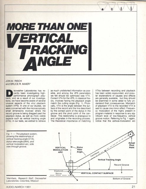
Fig. 1 - The playback system,<br />
showing the relationships of<br />
vertical tracking angle (VTA),<br />
stylus rake angle (SRA}, and<br />
vertical modulation arc; side<br />
view through groove.<br />
•Members, Research Staff, Discwasher<br />
Laboratories, Columbia, Missouri<br />
AUDIO/MARCH 1981<br />
as much undistorted information as possible,<br />
and among the VPS parameters<br />
we felt should be optimized was VTA.<br />
Correct VTA for the VPS, in classical theory,<br />
involves having the playback angle<br />
match the cutting angle (Fig. 1). Physically,<br />
VTA is the angle between the surface<br />
of the record and the line described<br />
by the contact point of the stylus in the<br />
groove and the pivot point of the cantilever.<br />
This relationship is analogous to<br />
and originates in the recording process.<br />
The theoretical importance of matching<br />
\ VERTICAL<br />
MODULATION<br />
ARC<br />
Diamond<br />
Stylus<br />
I<br />
I<br />
I I<br />
I<br />
f.t--....Stylus<br />
I Rake<br />
I Angle"<br />
I<br />
VTAs between recording and playback<br />
has been widely expounded, and popular<br />
explanations of causes and effects<br />
are generally available, but they should<br />
be examined in some detail to fully understand<br />
their consequences. Mismatch<br />
of playback VTA to the recorded VTA is<br />
said to cause one minor effect: Frequency<br />
modulation of the highs present in<br />
program material in response to any significant<br />
level of low-frequency vertical<br />
groove motion. Referring to Fig. 1 again,<br />
notice that the vertical-modulation arc<br />
Verllcal Tracking Angle<br />
,"'------yERTICAl CONTACT SURFACE<br />
Record Groove<br />
Bottom of Groove<br />
i<br />
Actual<br />
ptyot<br />
Point<br />
21
increased frequency modulation of 4<br />
kHz - a more objectionable form of distortion<br />
than harmonic distortion.<br />
The next step was to test for distortion<br />
differences between the optimization at<br />
VTA for proper SRA alignment or for vertical-modulation<br />
arc matching. At this<br />
stage of our experimentation, we attempted<br />
some tests using a Shibata-type<br />
stylus with a bent cantilever tube to give<br />
odd combinations of SRA-to-vertical<br />
modulation arc alignment. We were never<br />
able to make a satisfactorily "clean"<br />
bend due to the Shibata-type configuration<br />
and its need for critical vertical<br />
(head-on) alignment, but the data produced<br />
were intriguing.<br />
We were, however, fortunate 10 have<br />
in our stock of cartridges a unit deemed<br />
defective due to a stylus misalignment.<br />
This cartridge had a modified-Shibata<br />
stylus which was slanted more than a<br />
typical unit. When properly aligned for<br />
SRA, this cartridge was slightly more<br />
than 4 degrees "low" in proper VTA<br />
match. Figure 7 illustrates the results of<br />
the correct SRA versus correct VTA experiment,<br />
with the same basic data displayas<br />
Fig, 6. A distinct distortion increase<br />
is shown when SRA is misaligned<br />
ana the correct VTA match is also made.<br />
Compare Figs. 6 and 7, and it will be<br />
seen that for an equal degree of<br />
misatignment, the SRA parameter is<br />
most significant in causing a rise in distortion,<br />
especially higher order distortion<br />
products. Notice, too, that when the<br />
modified Shibata stylus is correctly<br />
aligned for SRA, distortion products are<br />
at lower levels than when VTA is correctly<br />
aligned for the conical stylus. These<br />
data are fairly conclusive regarding<br />
which parameter is of importance for different<br />
styli. •<br />
Reported listening tests concerning<br />
VTA alignment have said that as little as<br />
1/30 of a degree can make an audible<br />
difference in the clarity of the music, with<br />
a higher than optimal misalignment<br />
causing excess brightness. These reports<br />
typically do not distinguish between<br />
VTA and SRA even when the report<br />
mentions the existence of SRA. The<br />
results of our tests indicate that the<br />
parameter being optimized in these reports<br />
was almost undoubtedly SRA. Our<br />
own informal listening tests bear this out<br />
as well. When SRA is correctly aligned<br />
the sound quality "locks-in" and the retrieval<br />
of minute details is enhanced.<br />
ICBS STR 1t 2 test record. Band 7. Side B (400 Hz and 4 kHz).<br />
\ (<br />
V \J \t! \1I<br />
Table I - Frequency modulation data for different conditions.<br />
14 "<br />
16l-'i°<br />
19"<br />
21 y.! 0<br />
tl14°<br />
14 "<br />
16Y.!°<br />
Freq. Deviation at 4 kHz<br />
21%<br />
1.8%<br />
22%<br />
2.5%<br />
t.4%<br />
L 1%, R 0.6%<br />
L 1.3%, R 0.8%<br />
Mono 0.0% for<br />
both<br />
These conclusions were further confirmed<br />
by some tests utilizing a laterally<br />
modulated 50Q-Hz asymmetrical square<br />
wave cut from Denon test record XG<br />
7003. This recorded signal has a series<br />
of finely detailed harmonics extending<br />
above 40 kHz. We postulated that a<br />
misalignment of the stylus would alter or<br />
lose the harmonics. When a 4-degree tilt<br />
to the optimal SRA was introduced, alteration<br />
of the harmonics as low as 5<br />
kHz and 7 kHz occurred and tosses of<br />
harmonics above 30 kHz were evidentl<br />
These changes are subtle, but at the<br />
same time consistent and repeatable.<br />
We studied the frequency deviation<br />
for the 4-kHz component of the 1M tone<br />
used throughout these tests, An experimental<br />
comparator based on a PLL IC<br />
was used for these tests, While absolute<br />
accuracy may not hold, the relative rankings<br />
remain accurate. Table I lists the results<br />
of these measurements taken under<br />
various conditions of VTA. It can be<br />
seen from these figures that there is an<br />
alarming amount of distortion present,<br />
although in practice vertical modulation<br />
tends to be rare in recording. In fact, the<br />
thickness of the recording lacquer, commercial<br />
considerations, and engineering<br />
expertise generally keep vertical cutting<br />
low, and thus phase information<br />
coherent<br />
Our calculations indicate that maximum<br />
cantilever vertical-arc travel is typically<br />
1 degree due to these limitations.<br />
Another theoretical aspect of VTA match<br />
often overlooked is cantilever length,<br />
which should be matched between cutting<br />
and playback systems. There is no<br />
Modulation<br />
Vertical<br />
Vertical<br />
Vertical<br />
Vertical<br />
VerticaP<br />
Lateral<br />
Lateral<br />
Stylus Type Sum of 2nd-Order<br />
Sideband<br />
- (Maior Distortion<br />
Level)<br />
Conical<br />
Conical<br />
Conical<br />
Conical<br />
Shibata<br />
Shibata<br />
Conical<br />
12.0%<br />
t 1.1%<br />
12.8%<br />
t6.4%<br />
standard for these lengths, and cartridges<br />
we have examined show gross<br />
differences in cantilever length and do<br />
not correlate to cutting systems.<br />
Thus, our investigations clearly show<br />
SRA to be a more important controllable<br />
variable than VTA. Our dialogue with<br />
cutting engineers indicates that VTA currently<br />
varies between 16 and 22 degrees,<br />
depending on the lathe system.<br />
SRA, however, is generally 91 to 95 degrees<br />
relative to the record surface in order<br />
to facilitate lacquer "chip" (cutaway<br />
strand) removal.<br />
Proper hi-fi set-up should therefore<br />
concentrate on cartridge adjustment that<br />
has the tip of the stylus pointed "back"<br />
toward the tonearm pivot, and the top of<br />
the stylus tipped "forward" so that the<br />
contact SRA face is 92 degrees between<br />
the styl.us and the record surface.<br />
Such alignment will at least approximate<br />
correct SRA. (One cautionary note: True<br />
Shibata styli do not have their stylus contact<br />
area or footprint lined up with the<br />
bulk of the stylus chip, and this should<br />
be taken into account when adjusting for<br />
proper SRA.) The effects are clearly audible<br />
on a fine audio system. AI<br />
References<br />
1. Available from Gorham Audio Corp., 741 Washington<br />
51., New YoriI, N.Y. 10014.<br />
2. White, James V. and Arthur J. Gusr, "Three FM<br />
Methods fOf Measuring Tracking Angles ot Phono<br />
Pickups." jour, ollhe Audio Eng. Soc" Vol. 27. No.<br />
4, April. 1979. p, 242.<br />
3. Halter, Jefome B. and J.G. Woodward. "Vertical<br />
Tracking Angle Errors in Srereodlsk Systems, ,. Joor.<br />
01 the Audio Eng. Soc., Vol. 12, No.1, Jan.. 1964,<br />
p.8.<br />
AUDIO/MARCH 1981 25