Principles of Turbomachinery - New Age International
Principles of Turbomachinery - New Age International
Principles of Turbomachinery - New Age International

Create successful ePaper yourself
Turn your PDF publications into a flip-book with our unique Google optimized e-Paper software.
1.1 TURBOMACHINE<br />
1<br />
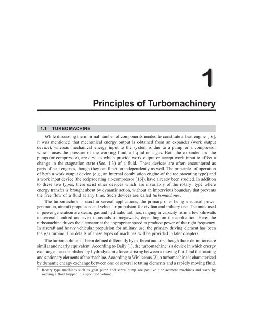
<strong>Principles</strong> <strong>of</strong> <strong>Turbomachinery</strong><br />
While discussing the minimal number <strong>of</strong> components needed to constitute a heat engine [16],<br />
it was mentioned that mechanical energy output is obtained from an expander (work output<br />
device), whereas mechanical energy input to the system is due to a pump or a compressor<br />
which raises the pressure <strong>of</strong> the working fluid, a liquid or a gas. Both the expander and the<br />
pump (or compressor), are devices which provide work output or accept work input to affect a<br />
change in the stagnation state (Sec. 1.3) <strong>of</strong> a fluid. These devices are <strong>of</strong>ten encountered as<br />
parts <strong>of</strong> heat engines, though they can function independently as well. The principles <strong>of</strong> operation<br />
<strong>of</strong> both a work output device (e.g., an internal combustion engine <strong>of</strong> the reciprocating type) and<br />
a work input device (the reciprocating air-compressor [16]), have already been studied. In addition<br />
to these two types, there exist other devices which are invariably <strong>of</strong> the rotary1 type where<br />
energy transfer is brought about by dynamic action, without an impervious boundary that prevents<br />
the free flow <strong>of</strong> a fluid at any time. Such devices are called turbomachines.<br />
The turbomachine is used in several applications, the primary ones being electrical power<br />
generation, aircraft propulsion and vehicular propulsion for civilian and military use. The units used<br />
in power generation are steam, gas and hydraulic turbines, ranging in capacity from a few kilowatts<br />
to several hundred and even thousands <strong>of</strong> megawatts, depending on the application. Here, the<br />
turbomachine drives the alternator at the appropriate speed to produce power <strong>of</strong> the right frequency.<br />
In aircraft and heavy vehicular propulsion for military use, the primary driving element has been<br />
the gas turbine. The details <strong>of</strong> these types <strong>of</strong> machines will be provided in later chapters.<br />
The turbomachine has been defined differently by different authors, though these definitions are<br />
similar and nearly equivalent. According to Daily [1], the turbomachine is a device in which energy<br />
exchange is accomplished by hydrodynamic forces arising between a moving fluid and the rotating<br />
and stationary elements <strong>of</strong> the machine. According to Wislicenus [2], a turbomachine is characterized<br />
by dynamic energy exchange between one or several rotating elements and a rapidly moving fluid.<br />
1 Rotary type machines such as gear pump and screw pump are positive displacement machines and work by<br />
moving a fluid trapped in a specified volume.
2 <strong>Turbomachinery</strong><br />
Binder [3] states that a turbomachine is characterized by dynamic action between a fluid and one<br />
or more rotating elements. A definition to include the spirit <strong>of</strong> all the preceding definitions would be:<br />
A turbomachine is a device in which energy transfer occurs between a flowing fluid and a<br />
rotating element due to dynamic action resulting in a change in pressure and momentum <strong>of</strong><br />
the fluid. Mechanical energy transfer occurs into or out <strong>of</strong> the turbomachine, usually in steady flow.<br />
Turbomachines include all those types that produce large-scale power and those that produce a<br />
head or pressure, such as centrifugal pumps and compressors.<br />
The principal components <strong>of</strong> a turbomachine are: (i) A rotating element carrying vanes<br />
operating in a stream <strong>of</strong> fluid, (ii) A stationary element or elements which generally act as<br />
guide vanes or passages for the proper control <strong>of</strong> flow direction and the energy conversion<br />
process, (iii) an input and/or an output shaft, and (iv) a housing (Fig. 1.1). The rotating element<br />
carrying the vanes is also known by the names rotor, runner, impeller, etc., depending upon the<br />
particular application. Energy transfer occurs only due to the exchange <strong>of</strong> momentum between<br />
the flowing fluid and the rotating elements; there may not be even a specific boundary that the<br />
fluid is not permitted to cross. Details relating to these will be discussed in the following sections.<br />
Inlet<br />
Rotor<br />
Stator or housing<br />
Stator blade<br />
Rotor blade<br />
Blade tip<br />
Exit<br />
Shaft<br />
Fig. 1.1. Schematic cross-sectional view <strong>of</strong> a turbine showing the principal parts <strong>of</strong> the<br />
turbomachine.<br />
The stationary element is also known by different names—among them guide-blade or<br />
nozzle—depending on the particular machine and the kind <strong>of</strong> flow occurring in it. A stationary<br />
element is not a necessary part <strong>of</strong> every turbomachine. The common ceiling fan used in many<br />
buildings in India to circulate air during summer and the table fan are examples <strong>of</strong> turbomachines<br />
with no stationary element. Such machines have only two elements <strong>of</strong> the four mentioned above:<br />
an input shaft and a rotating blade element.<br />
Either an input or an output shaft or both may be necessary depending on the application.<br />
If the turbomachine is power-absorbing, the enthalpy <strong>of</strong> the fluid flowing through it increases<br />
due to mechanical energy input at the shaft. If the turbomachine is power-generating,<br />
mechanical energy output is obtained at the shaft due to a decrease in enthalpy <strong>of</strong> the flowing<br />
fluid. It is also possible to have power-transmitting turbomachines which simply transmit power<br />
from an input shaft to an output shaft, just like a clutch-plate gear drive in a car which transmits<br />
the power generated by the reciprocating engine to the shaft which drives the wheels. In principle,
<strong>Principles</strong> <strong>of</strong> <strong>Turbomachinery</strong><br />
the device acts merely as an energy transmitter to change the speed and torque on the driven<br />
member as compared with the driver. There are many examples <strong>of</strong> these types <strong>of</strong> machines.<br />
Examples <strong>of</strong> power-absorbing turbomachines are mixed-flow, axial-flow and centrifugal pumps,<br />
fans, blowers and exhausters, centrifugal and axial compressors, etc. Examples <strong>of</strong> powergenerating<br />
devices are steam, gas and hydraulic turbines. The best known examples <strong>of</strong> powertransmitting<br />
turbomachines are fluid-couplings and torque-converters for power transmission used<br />
in automobiles, trucks and other industrial applications.<br />
The housing too is not a necessary part <strong>of</strong> a turbomachine. When present, it is used to<br />
restrict the fluid flow to a given space and prevent its escape in directions other than those<br />
required for energy transfer and utilization. The housing plays no role in the energy conversion<br />
process. The turbomachine that has housing is said to be enclosed and that which has no housing<br />
is said to be extended [4]. The ceiling-fan shown in Fig. 1.2 is an example <strong>of</strong> an extended<br />
turbomachine and all the rest shown in the figure are enclosed turbomachines.<br />
Rotor Stator or Guide-blade<br />
(a) Axial flow fan<br />
Rotor<br />
Exit<br />
0.5 to 1D 3<br />
Guide<br />
Wheel<br />
2.5 to<br />
3D 3<br />
Shaft Guide Blades<br />
Draft tube<br />
Tail Race<br />
Rolor<br />
Wheel<br />
Runner<br />
(b) Radial Outward Flow Fan (c) Mixed Flow Francis Turbine<br />
(d) Extended<br />
D 3<br />
Spiral<br />
Casing<br />
Guide Blades<br />
Fig. 1.2. Classification based on fluid flow in turbomachine.<br />
Turbomachines are also categorized by the direction <strong>of</strong> fluid flow as shown in Fig. 1.2. The<br />
flow directions are: (i) axial, (ii) radial and (iii) mixed. In the axial-flow and radial-flow<br />
turbomachines, the major flow directions are approximately axial and radial respectively, while<br />
in the mixed-flow machine, the flow usually enters the rotor axially and leaves radially or vice<br />
versa. Mixed flow may also involve flow over the surface <strong>of</strong> a cone. An example <strong>of</strong> a mixedflow<br />
machine is a mixed-flow pump. A radial flow machine may also be classified into radial<br />
inward flow(centripetal) or radial outward flow(centrifugal) types depending on whether<br />
the flow is directed towards or away from the shaft axis.<br />
3
4 <strong>Turbomachinery</strong><br />
1.2 POSITIVE-DISPLACEMENT DEVICES AND TURBOMACHINES<br />
In a positive-displacement machine2 , the interaction between the moving part and the fluid<br />
involves a change in volume and/or a translation <strong>of</strong> the fluid confined in a given boundary. During<br />
energy transfer, fluid expansion or compression may occur in a positive-displacement machine<br />
without an appreciable movement <strong>of</strong> the mass centre-<strong>of</strong>-gravity <strong>of</strong> the confined fluid. As such,<br />
changes in macroscopic kinetic energy and momentum may be neglected in most <strong>of</strong> these machines.<br />
The movement <strong>of</strong> a piston or gear-tooth causes changes in fluid volume because <strong>of</strong> the<br />
displacement <strong>of</strong> the boundaries, i.e., the fluid cannot escape from the boundaries except due to<br />
unavoidable leakage. An expansion or contraction may occur if the fluid is compressible as for<br />
example, in a balloon being filled with air. The action is therefore nearly static and completely<br />
different from that <strong>of</strong> a turbomachine where the action is fast, dynamic and the energy transfer<br />
occurs without the necessity for a confining boundary. (In compressible flow handling machines,<br />
fluid flows at very high velocities approaching acoustic speed at certain locations).<br />
The differences between positive-displacement machines and turbomachines are clarified<br />
further by comparing their modes <strong>of</strong> action, operation, energy transfer, mechanical features etc.,<br />
in the following:<br />
● Action: A positive-displacement machine creates thermodynamic and mechanical action<br />
between a nearly static fluid and a relatively slowly moving surface. It involves a change<br />
in volume or a displacement (bodily movement <strong>of</strong> the confined fluid).<br />
A turbomachine creates thermodynamic and dynamic interaction between a flowing fluid<br />
and rotating element and involves energy transfer with pressure and momentum changes.<br />
There is no positive confinement <strong>of</strong> the fluid at any point in the system.<br />
● Operation: The positive-displacement machine commonly involves a reciprocating motion<br />
and unsteady flow <strong>of</strong> the fluid, though it is not impossible for the machine to have a purely<br />
rotary motion and nearly steady flow. Examples <strong>of</strong> such rotating positive-displacement<br />
machines are gear-pumps and screw-pumps. However, since the fluid containment is<br />
positive, stopping a positive-displacement machine during operation may trap a certain<br />
amount <strong>of</strong> fluid and maintain it indefinitely in a state different from that <strong>of</strong> the surroundings,<br />
if heat transfer and leakage are completely absent in a theoretical sense.<br />
Screw pump Gear pump<br />
Fig. 1.3. Screw pump and gear pump.<br />
2 A positive-displacement machine is one which takes a fresh charge at the beginning <strong>of</strong> each cycle and discharges<br />
it at the completion <strong>of</strong> the cycle.
<strong>Principles</strong> <strong>of</strong> <strong>Turbomachinery</strong><br />
The turbomachine involves, in principle, a steady flow <strong>of</strong> fluid and a purely rotary motion<br />
<strong>of</strong> the mechanical element. A turbomachine may also involve unsteady flow for short<br />
periods <strong>of</strong> time, especially while starting, stopping or during changes <strong>of</strong> loads. However, in<br />
most instances, the machine is designed for steady-flow operation. As there is no positive<br />
containment <strong>of</strong> the fluid, stopping <strong>of</strong> the machine will let the fluid undergo a change <strong>of</strong><br />
state (in a matter <strong>of</strong> milliseconds), and become the same as that <strong>of</strong> the surroundings.<br />
● Mechanical Features: The positive-displacement machine commonly involves rather<br />
low speeds and is relatively complex in mechanical design. It is usually heavy per unit<br />
<strong>of</strong> output and employs valves which are open only part <strong>of</strong> the time, as in reciprocating<br />
machines. Also, rather heavy foundations are usually needed because <strong>of</strong> reciprocating<br />
masses and consequent vibration problems. Generally in such machines, the mechanical<br />
features are more complex than in turbomachines.<br />
Turbomachines usually employ high rotational speeds, are simple in design principle and<br />
are generally light in weight per unit <strong>of</strong> power output. Their foundations may be quite light<br />
since vibration problems are not severe. They do not employ valves that open and close<br />
during steady-state operation. Usually, only inexpensive associated equipment is required.<br />
● Efficiency <strong>of</strong> Conversion Process: In positive-displacement machines, the use <strong>of</strong><br />
positive containment and a nearly static energy transfer process may result in a higher<br />
efficiency relative to that <strong>of</strong> a turbomachine which employs a dynamic process including<br />
high-speed fluid flow. The higher efficiency <strong>of</strong> energy conversion used to be the<br />
advantage <strong>of</strong> a positive-displacement machine as compared with a turbomachine which<br />
used to exhibit somewhat lower efficiencies. Compression by dynamic action <strong>of</strong>ten<br />
involves higher losses and hence lower efficiencies, though expansion in a turbomachine<br />
results in better efficiencies than in compression. Nevertheless, both these <strong>of</strong>ten used<br />
to fall short <strong>of</strong> the corresponding reciprocating machine in performance. In modern<br />
turbomachines which are designed through the aid <strong>of</strong> computers with high quality, efficient<br />
s<strong>of</strong>tware, the difference between compressive and expansive efficiencies is not large<br />
and these are both the same as the efficiencies obtainable with reciprocating machines.<br />
● Volumetric Efficiency: The volumetric efficiency <strong>of</strong> a machine with positive-displacement<br />
is normally well below that <strong>of</strong> turbomachines and in some cases, very low because <strong>of</strong><br />
the opening and the closing <strong>of</strong> valves needed for continuous operation. In turbomachines,<br />
during steady state operation, there exist no inlet and outlet valves and the volumetric<br />
efficiency differs little from 100%. Also, since the flow is continuous and the fluid<br />
velocities are high, a turbomachine has a high fluid handling capacity per kilogram weight<br />
<strong>of</strong> the machine. As an example, a 300 kW gas turbine plant typically handles about<br />
22 kg.s –1 <strong>of</strong> air and has a weight <strong>of</strong> 900 kg. Thus, the specific power output <strong>of</strong> this<br />
plant is 15 kJ.kg –1 <strong>of</strong> air and it has a power plant weight per unit mass flow rate <strong>of</strong> air<br />
between 10 and 100. In comparison, an aircraft reciprocating power plant producing<br />
300 kW handles 2 kg.s –1 <strong>of</strong> air and has a weight <strong>of</strong> 1000 kg. Thus, its specific weight<br />
is 500 per kg.s –1 <strong>of</strong> air flow. For all types <strong>of</strong> industrial power plants, the specific weight<br />
<strong>of</strong> a reciprocating plant is about 10-15 times that <strong>of</strong> a turbo-power plant.<br />
5
6 <strong>Turbomachinery</strong><br />
● Fluid Phase Change and Surging: Phase changes occurring during flow through a<br />
turbomachine can frequently cause serious difficulties to smooth operation. Examples <strong>of</strong><br />
these are cavitation at pump inlets and hydraulic turbine outlets as well as condensation<br />
in steam turbines resulting in blade erosion and/or a deterioration <strong>of</strong> machine performance.<br />
Surging or pulsation (Chapter 6, a phenomenon associated with turbomachinery), is caused<br />
by an unstable flow situation due to a rising head-discharge characteristic. It is<br />
characterized by the pulsation <strong>of</strong> fluid pressure between the inlet and the outlet <strong>of</strong> the<br />
turbomachine, i.e., the reversal <strong>of</strong> flow direction accompanied by violent flow fluctuations.<br />
The machine may vibrate violently, and under certain operating conditions, may even be<br />
damaged by these vibrations. The performance <strong>of</strong> the device deteriorates considerably<br />
even when the flow fluctuations are not violent. Problems <strong>of</strong> phase change pulsation<br />
and surging are <strong>of</strong> no importance in positive-displacement machines.<br />
1.3 STATIC AND STAGNATION STATES<br />
In dealing with turbomachines, one is concerned with fluids, <strong>of</strong>ten compressible and moving<br />
at high speeds exceeding the speed <strong>of</strong> sound. Even in turbomachines dealing with<br />
incompressible fluids where the velocities are relatively low, the kinetic and potential energies<br />
<strong>of</strong> the fluid are <strong>of</strong>ten large and constitute major fractions <strong>of</strong> the total energy available for<br />
conversion into work. Simplistic approaches which neglect potential and kinetic energies cannot<br />
provide sufficiently accurate results for design. It is therefore necessary to formulate equations<br />
based on the actual state <strong>of</strong> the fluid including all the energies at the given point in the flow.<br />
Taking these factors into account, we use the equations <strong>of</strong> the First and Second laws <strong>of</strong><br />
Thermodynamics to specify two fluid states called respectively, the ‘Static’ and the ‘Stagnation<br />
States’ which will be discussed below.<br />
● The Static State: First, consider a fluid flowing at a high speed through a duct. In<br />
order to measure the properties <strong>of</strong> the fluid, one may insert an instrument such as a<br />
pressure gauge or a thermometer at some point in the flow. One can imagine two types<br />
<strong>of</strong> measurements, one in which the measuring instrument moves at the same local speed<br />
as that <strong>of</strong> the fluid particle and another in which it is stationary with respect to the<br />
particle the properties <strong>of</strong> which are under investigation. Measurements <strong>of</strong> the first type<br />
made with an instrument which moves with the same local speed as the particle are<br />
said to determine a ‘static’ property <strong>of</strong> the fluid. Note that what is stationary is neither<br />
the fluid nor the instrument to measure the property—both <strong>of</strong> them may move except<br />
that the measuring instrument moves at the same speed as the fluid locally and is therefore<br />
at rest with respect to the particle <strong>of</strong> the fluid. For example, one can consider a<br />
pressure measurement made with a static pressure gauge which is usually fixed to the<br />
side <strong>of</strong> the duct. In this case, the fluid particle and the instrument are at rest with respect<br />
to each other at the point where the measurement is being made. Hence, the<br />
measured pressure is a static pressure. Any measurement made in consonance with<br />
this stipulation determines a static property, be it one <strong>of</strong> pressure, temperature, volume,<br />
or any other, as specified. The state <strong>of</strong> the particle fixed by a set <strong>of</strong> static properties is<br />
called the ‘Static State’.
<strong>Principles</strong> <strong>of</strong> <strong>Turbomachinery</strong><br />
● The Stagnation or Total State3 : The stagnation state is defined as the terminal state<br />
<strong>of</strong> a fictitious, isentropic, work-free and steady-flow process during which the<br />
macroscopic kinetic and potential energies <strong>of</strong> the fluid particle are reduced to zero,<br />
the initial state for the process being the static state. The macroscopic kinetic and potential<br />
energies are those measured with respect to an arbitrary and pre-specified datum state.<br />
The stagnation state as specified above is not representative <strong>of</strong> any true state <strong>of</strong> the fluid.<br />
No real process leads to the stagnation state, because no real process is truly isentropic and<br />
perfectly free from thermal exchange with the surroundings. Despite the impossibility <strong>of</strong> achieving<br />
it, if proper care is taken to account for errors in measurement and appropriate corrections<br />
incorporated, many <strong>of</strong> the properties measured with instruments like Pitot tubes, thermocouples,<br />
etc., do provide readings that approximate stagnation properties closely. Further, stagnation property<br />
changes provide ideal values against which real machine performance can be compared. These<br />
properties and the state defined by them (the stagnation state), are thus <strong>of</strong> great importance in<br />
turbomachinery.<br />
By using the definition <strong>of</strong> a stagnation state, it is possible to obtain expressions for stagnation<br />
properties in terms <strong>of</strong> static properties. Considering any steady-flow process, the First Law <strong>of</strong><br />
Thermodynamics [15] gives the equation:<br />
q – w = ∆h + ∆ke + ∆pe, …(1.1)<br />
where, q and w are respectively the energy transfers as heat and work per unit mass flow, h is<br />
the static enthalpy and ke and pe are respectively the macroscopic kinetic and potential energies<br />
per unit mass. It is known that ke = V2 /2, and pe = gz, V, being the fluid particle velocity and<br />
z, the height <strong>of</strong> the particle above the datum at the point under consideration.<br />
Since the static state is the initial state in a fictitious isentropic, work-free, steady flow process<br />
and the stagnation state is the terminal state where both the kinetic and potential energies are<br />
zero, the difference in enthalpies between the stagnation and static states is obtained by setting<br />
q = w = 0, ∆h = ho – hi, keo = 0 and peo = 0 in Eq. (1.1). There is then obtained:<br />
ho – (hi + kei + pei) = 0 or, ho = (h + ke + pe), …(1.2)<br />
where the subscript o represents the stagnation state and i represents the initial static state.<br />
Equation (1.2) follows from the fact that at the stagnation state, both the kinetic and the potential<br />
energies are zero. In the last part <strong>of</strong> Eq. (1.2), the subscript, i, has been removed and from<br />
here onwards, the properties at the static state will be indicated without the subscript as shown.<br />
The enthalpy ho in the stagnation state has thus been expressed in terms <strong>of</strong> three known<br />
properties, h, ke and pe <strong>of</strong> the static state.<br />
As stated earlier, it is necessary that the process changing the state from static to stagnation<br />
be isentropic, i.e., so = s, and hence, the entropy in the stagnation state is equal to the entropy<br />
in the static state. Thus, two independent stagnation properties, namely the enthalpy ho and the<br />
entropy so, have been determined in terms <strong>of</strong> the known properties at the static state. Since<br />
3 This definition was given by Dean R.H. Zimmerman who was Visiting Pr<strong>of</strong>essor <strong>of</strong> Mechanical<br />
Engineering at the start <strong>of</strong> IIT-K, 1962-1967.<br />
7
8 <strong>Turbomachinery</strong><br />
according to the ‘State Postulate’, the knowledge <strong>of</strong> any two independent properties at a specified<br />
state is sufficient to fix the state <strong>of</strong> a simple compressible substance [15], the stagnation state<br />
is totally determined and it should be possible to determine any other required property <strong>of</strong> the<br />
stagnation state in terms <strong>of</strong> the two known properties, h o and s o. Also, according to the Second<br />
Law <strong>of</strong> Thermodynamics, since T.ds = dh – v.dp, and the entropy remains constant in the change<br />
from static to stagnation state, ds = 0 and dh = v.dp, v = 1/ρ, being the specific volume and ρ,<br />
the density. Hence, integration yields for the change from static to stagnation state:<br />
h o – h = ∫ dh = ∫ v.dp. …(1.3)<br />
The integration on the right hand side depends on the variation <strong>of</strong> volume with respect to<br />
pressure in an isentropic process. If the p-v property relation is known, the equation above may<br />
be integrated and one can determine the stagnation pressure po in terms <strong>of</strong> the static enthalpy<br />
h and the static pressure p. This will be done for two special cases.<br />
(a) Incompressible Fluid: For an incompressible fluid, dv = d(1/ρ) = 0, ρ being the<br />
density <strong>of</strong> the fluid. Since the density is constant and independent <strong>of</strong> state:<br />
ho – h = (po – p)/ρ.<br />
Thus, on using Eq. (1.2), po/ρ = p/ρ + (ho – h) = p/ρ + V 2 /2 + gz. …(1.4)<br />
The stagnation pressure <strong>of</strong> the incompressible fluid has now been expressed in terms <strong>of</strong> its<br />
static pressure, velocity and height above a specified datum. According to the First Law <strong>of</strong><br />
Thermodynamics, the stagnation enthalpy ho and the stagnation pressure po should be<br />
constant along any streamline which experiences no energy transfer as heat or as work.<br />
Hence, for an incompressible, frictionless fluid in steady flow, it is seen that the stagnation pressure<br />
remains a constant along a streamline in an un-accelerated coordinate system. This is the<br />
Bernoulli’s theorem studied in Fluid Mechanics.<br />
In addition, for a change from the static to the stagnation state <strong>of</strong> an incompressible fluid,<br />
since there is no entropy change and p.dv = 0, T.ds = du + p.dv yields du = 0. Hence, u = uo, i.e., the internal energies <strong>of</strong> an incompressible fluid in the static and stagnation states are<br />
equal. Moreover, since the internal energy <strong>of</strong> an incompressible fluid is a function <strong>of</strong> temperature<br />
alone, one concludes that:<br />
uo – u = c(To – T) = 0, i.e., To = T. …(1.5)<br />
The local static and stagnation temperatures are equal to each other at every point in<br />
incompressible and loss-free fluid flow.<br />
(b) Perfect Gas: Since the enthalpy <strong>of</strong> a perfect gas is a function <strong>of</strong> temperature alone,<br />
from Eq. (1.2), with ke = V 2 /2 and pe = gz one gets:<br />
cpTo = cpT + V 2 /2 + gz or To = T + (V 2 /2 + gz)/cp. …(1.6)<br />
In compressible flow machines, fluid velocities vary from about 60 m.s –1 to 600 m.s –1 or<br />
more, whereas the maximum value <strong>of</strong> z is rarely in excess <strong>of</strong> 4 m in most steam and gas<br />
turbines. As such, even at the minimum flow velocity,<br />
V2 /2 = 602 /2 = 1800 J.kg –1 and, gz = (9.81)(4) = 39.24 J.kg –1 .
<strong>Principles</strong> <strong>of</strong> <strong>Turbomachinery</strong><br />
The calculations above indicate that the magnitude <strong>of</strong> kinetic energy is far in excess <strong>of</strong> the<br />
potential energy in most compressible flow machines. It is therefore usual to neglect the term<br />
gz in comparison with the term V 2 /2 and to write the equation to compute the stagnation<br />
temperature <strong>of</strong> a perfect gas in the form:<br />
To = T + V2 /(2cp). …(1.7)<br />
One can now determine the stagnation temperature by using the substitution cp = γR/( γ – 1),<br />
to obtain:<br />
To = T[1 + (γ – 1)V 2 /(2γRT)] or …(1.8a)<br />
povo = pv[1 + (γ – 1)M 2 /2], …(1.8b)<br />
where M, is the local Mach number <strong>of</strong> a perfect gas defined by the equation M = V/a, in which<br />
the speed <strong>of</strong> sound in the gas at the static temperature T, is denoted by the symbol<br />
a = (γRT) 1/2 . Again, since for the isentropic expansion <strong>of</strong> a perfect gas, vo/v = (p/po) 1/γ , one<br />
can write:<br />
(po/p) = βγ/(γ – 1) , β = 1 + (γ – 1)M2 /2. …(1.9a)<br />
With this simplification in notation, the expressions for the stagnation temperature To, (Eq. 1.8a) and stagnation pressure po (Eq. 1.9a) may be rewritten in the forms:<br />
To = T.β, and po = p.β (γ –1)/γ . ...(1.9b)<br />
Example 1.1. Dry saturated steam at 1 atm. static pressure flows through a pipe with a velocity<br />
<strong>of</strong> 300 m.s –1 . Evaluate the stagnation (total) pressure and the stagnation temperature <strong>of</strong> the steam:<br />
(a) By using steam tables and (b) by assuming steam to behave as a perfect gas with γ = 1.3.<br />
Data: Sat. Steam flow, static pr. p = 1.013 bar, velocity V = 300 m.s –1 .<br />
Find: The stagnation pressure po and the stagnation temperature To, (i) Use steam tables,<br />
(ii) Treat steam as a perfect gas with γ = 1.3.<br />
Solution: In working this example and other examples in Chapters 1 and 2, the use <strong>of</strong> Steam<br />
Tables and Mollier chart will be exhibited, though it is possible to solve the problem with the<br />
help <strong>of</strong> a computer program without the use <strong>of</strong> either the tables or the chart. The procedure<br />
for writing a computer program to solve similar problems will be provided in Chapter 3.<br />
(i) The static temperature corresponding to a saturation pressure <strong>of</strong> 1.013 bar is<br />
T = 100°C. By referring to the steam tables for the properties <strong>of</strong> saturated steam at<br />
the temperature 100°C (Table A.2 from Appendix A), we get for the static enthalpy,<br />
h = 2675.9 kJ.kg –1 and for the saturation static entropy s = 7.3549 kJ.kg –1 K –1 . Hence,<br />
from Eq. (1.6), neglecting potential energy (since steam is a compressible substance<br />
and its potential energy is small), one gets for the stagnation enthalpy Eq. (1.7),<br />
ho = h + ke + pe = 2675.9 + 3002 /(2 × 1000) = 2720.9 kJ.kg –1 .<br />
Stagnation entropy, so = s (static entropy) = 7.3549 kJ.kg –1 K –1 .<br />
On referring to the Mollier chart with the values <strong>of</strong> ho and so specified above, we get:<br />
Total pressure, po = 1.246 bar; Total temperature To = 121°C.<br />
9
10 <strong>Turbomachinery</strong><br />
(ii) If steam behaves as a perfect gas with γ = 1.3 and R = 8317/18 = 462.06 J.kg –1 K –1 ,<br />
To = T[1 + (γ γ – 1)V 2 /(2γRT)]<br />
= 373.15{1 + 0.3 × 300 2 /[2(1.3)(462.06)(373.15)]} = 395.63 K = 122.5°C.<br />
This newly calculated value <strong>of</strong> total temperature agrees reasonably well with that<br />
calculated by using Mollier chart and is therefore satisfactory. Then, stagnation pressure:<br />
po = p(To/T) γ/(γ γ γ<br />
γ – 1) = 1.013(395.63/373.15) 3.5 = 1.243 bar.<br />
The newly computed pressure agrees even better with the previous value obtained by<br />
using steam tables. This is the reason that for quick calculations, we can simply use the<br />
perfect gas equations and obtain reasonably good results. The fact that superheated steam<br />
behaves nearly like a perfect gas can be used to obtain quick approximations to the<br />
properties when its pressure is well below critical. This fact will be utilized in Chapter3<br />
to write a computer program to calculate the states <strong>of</strong> superheated steam undergoing<br />
an isentropic expansion.<br />
1.4 FIRST AND SECOND LAWS OF THERMODYNAMICS APPLIED TO<br />
TURBOMACHINES<br />
Fluid flow in turbomachines always varies in time, though it is assumed to be steady when<br />
a constant rate <strong>of</strong> power generation occurs on an average. This is due to small load fluctuations,<br />
unsteady flow at blade-tips, the entry and the exit, separation in some regions <strong>of</strong> flow etc., which<br />
cannot avoided, no matter how good the machine and load stabilization may be. Similar statements<br />
can be made for power absorbing turbomachines as well. Nevertheless, on an overall basis when<br />
the average over a sufficiently long time is considered, turbomachine flows may be considered<br />
as steady. This assumption permits the analysis <strong>of</strong> energy and mass transfer by using the steadystate<br />
control volume equations. Assuming further that there is a single inlet and a single outlet<br />
for the turbomachine across the sections <strong>of</strong> which the velocities, pressures, temperatures and<br />
other relevant properties are uniform, one writes the steady flow equation <strong>of</strong> the First Law <strong>of</strong><br />
Thermodynamics in the form:<br />
Q + m (h1 + V 2<br />
1 /2 + gz1) = P + m (h2 + V 2<br />
2 /2 + gz2). …(1.10)<br />
Here, Q = Rate <strong>of</strong> energy transfer as heat across the boundary <strong>of</strong> the control volume,<br />
P = Power output due to the turbomachine, and<br />
m = Mass flow rate.<br />
Note: While making calculations, if enthalpy h is expressed in kJ.kg –1 , then both the kinetic and<br />
potential energy terms, V2 /2 and gz in Eq. (1.10) and other similar equations should be divided<br />
by 1000 during calculations.<br />
Since ho = h + V 2 /2 + gz, (Eq. 1.3), one obtains:<br />
q – w = ∆ho, where, ∆ho = ho2 – ho1, …(1.11a)
<strong>Principles</strong> <strong>of</strong> <strong>Turbomachinery</strong><br />
represents the change in stagnation enthalpy between the inlet and the outlet <strong>of</strong> the<br />
turbomachine. Also, q = Q/ m and, w = P/ m represent respectively, the heat and mass transfer<br />
per unit mass flow through the control volume.<br />
Generally, all turbomachines are well-insulated devices. Even though the fluid velocity is high<br />
and the fluid passes through the turbomachine within fractions <strong>of</strong> a millisecond in steam and<br />
gas turbines, the energy loss through the insulation is very small (usually, q < 0.25% <strong>of</strong> w). In<br />
incompressible flow devices involving liquids like water and oil, there is no heat transfer possible<br />
since most <strong>of</strong> them operate at room temperature. Further, even when they handle warm liquids,<br />
the specific heats are so high that the liquids undergo negligible temperature changes during<br />
their passage through the pump. By neglecting q therefore, one can treat a turbomachine like a<br />
perfectly insulated device for which:<br />
∆ho = – w = – P/ m or, dho = – δw, …(1.11b)<br />
where the second part <strong>of</strong> the above equations applies to a device that gives rise to infinitesimally<br />
small changes in fluid stagnation enthalpy. The energy transfer as work is therefore numerically<br />
equal to the change in stagnation enthalpy <strong>of</strong> the fluid between the inlet and the outlet <strong>of</strong> the<br />
turbomachine.<br />
In a power-generating turbomachine, w is positive as defined so that ∆ho is negative, i.e.,<br />
the stagnation enthalpy at the exit <strong>of</strong> the machine is less than that at the inlet. The machine<br />
puts out work at the shaft. In a power-absorbing turbomachine, ∆ho is positive. The stagnation<br />
enthalpy at the outlet will be greater than that at the inlet and work is done on the flowing fluid<br />
due to the rotation <strong>of</strong> the shaft. As already shown in the example preceding Eq. (1.7), in<br />
turbomachines handling compressible fluids, changes in static head cause negligible changes in<br />
total enthalpy. For these machines therefore, it is sufficiently accurate to write:<br />
w = – ∆ho = – ∆(h + V 2 /2). …(1.11c)<br />
In machines dealing with liquids, since the effects <strong>of</strong> changes in potential energy are large<br />
and changes in internal energy are negligible (as shown later, Example 1.3), the density is constant<br />
and one can write:<br />
w = – ∆ho = – ∆(p/ρ + V 2 /2 + gz). …(1.11d)<br />
In a turbomachine, the energy transfer between the fluid and the blades can occur only by<br />
dynamic action, i.e., through an exchange <strong>of</strong> momentum between the rotating blades (Fig. 1.4,<br />
location 3) and the flowing fluid. It thus follows that all the work is done when the fluid flows<br />
over the rotor-blades and not when it flows over the stator-blades. As an example, considering<br />
a turbomachine with a single stator-rotor combination shown schematically in Fig. 1.4, let points<br />
1 and 2 represent respectively the inlet and the exit <strong>of</strong> the stator. Similarly, points 3 and 4<br />
represent the corresponding positions for the rotor blades. Then ideally for flow between points<br />
1 and 2, there should be no stagnation enthalpy changes since no energy transfer as heat or<br />
work occurs in the stator. Thus, ho1 = ho2. For flow between points 3 and 4 however, the<br />
stagnation enthalpy change may be negative or positive, depending upon whether the machine<br />
is power-generating or power-absorbing. Hence, ho3 > ho4 if the machines develops power and<br />
if ho3 < ho4, the machine needs a driver and absorbs power.<br />
11
12 <strong>Turbomachinery</strong><br />
Shaft Exit<br />
Inlet<br />
1 2<br />
3 4<br />
Rotor<br />
Stator blade<br />
Fig. 1.4. Schematic section <strong>of</strong> a Single-stage turbomachine.<br />
A large machine is generally a combination <strong>of</strong> stator-rotor stages <strong>of</strong> the type described above.<br />
If the effects <strong>of</strong> friction and other losses are neglected, there can be no stagnation enthalpy<br />
changes in any stator-blade or nozzle. The stator is thus essentially a flow-directing device in<br />
which only static enthalpy, kinetic and potential energies can change, leaving the stagnation<br />
properties unaltered. In the rotor stages, dynamic interaction occurs between the fluid and the<br />
blades leading to energy exchange as work and consequently, changes in stagnation properties.<br />
If the system is perfectly reversible and adiabatic with no energy transfer as work, no<br />
changes can occur in the stagnation properties (enthalpy, pressure and temperature) between<br />
the inlet and the outlet <strong>of</strong> the machine. All turbomachines exchange work with the fluid and<br />
also suffer from frictional as well as other losses. The effect <strong>of</strong> the losses in a power-generating<br />
machine is to reduce the stagnation pressure and to increase entropy so that the net work output<br />
is less than that in an ideal process. The corresponding work input is higher in a power-absorbing<br />
machine as compared with that in an ideal process. In order to understand how this happens,<br />
consider the Second Law equation <strong>of</strong> state, Todso = dho – vodpo. (This is the form <strong>of</strong> the<br />
equation Tds = dh – vdp, when applied to stagnation properties.) Also, dho = –δw, as<br />
demonstrated earlier (Eq. 1.11b). Hence,<br />
–δw = vodpo + Todso. …(1.11e)<br />
In a power-generating machine, dpo is negative since the flowing fluid undergoes a pressure<br />
drop when mechanical energy output is obtained. However, the Clausius inequality [15] requires<br />
that Todso ≥ δq, and as δq ≈ 0, in a turbomachine Todso ≥ 0. The sign <strong>of</strong> equality applies only to<br />
a reversible process which has a work output δw = – vodpo > 0. In a real machine, Todso > 0, so<br />
that δwi – δw = Todso > 0 and represents the decrease in work output due to the irreversibilities<br />
in the machine. The reversible power-generating machine therefore exhibits the highest mechanical<br />
output <strong>of</strong> all the machines undergoing a given stagnation pressure change. A similar argument may<br />
be used to prove that if the device absorbs power, the work input needed to obtain a specified<br />
stagnation pressure rise is a minimum when the device is reversible. In this case, δwi – δw = Todso > 0,<br />
so that both the ideal work δwi and the actual work δw are negative, the actual work being larger<br />
than the ideal work in magnitude.
<strong>Principles</strong> <strong>of</strong> <strong>Turbomachinery</strong><br />
Example 1.2. A turbomachine handling liquid water is located 8 m above the sump level and<br />
delivers the liquid to a tank located 15 m above the pump. The water velocities in the inlet and<br />
the outlet pipes are respectively 2 m.s –1 and 4 m.s –1 . Find the power required to drive the pump<br />
if it delivers 100 kg.min –1 <strong>of</strong> water.<br />
Data: Pump handling liquid water <strong>of</strong> constant density ρ = 1000 kg.m –3 , z1 = 8 m,<br />
z2 = 15 m, V1 = 2 m.s –1 , V2 = 4 m.s –1 , mass flow rate = 100 kg.min –1 .<br />
Find: Power needed to drive the pump, P.<br />
Solution: Liquid water may be considered as incompressible in the pressure range <strong>of</strong> operation<br />
<strong>of</strong> most pumps so that we can assume that the enthalpy is a function <strong>of</strong> density alone and is<br />
independent <strong>of</strong> temperature. With these assumptions, we get:<br />
w = q – ∆ho = – ∆po/ρ, = – [(p2 – p1)/ρ + (V 2<br />
2 – V1<br />
2 )/2 + g(z2 – z1)] = [0 + (42 – 22 )/2 + 9.81(15 + 8)] = 231.6 J.kg –1 .<br />
Note the following:<br />
(i) The pressure difference (p2 – p1) is taken as zero, since both the sump from which the<br />
water is drawn and the delivery tank are open to atmosphere.<br />
(ii) The value <strong>of</strong> z1 is – 8 m, since the measurements are made with respect to the location<br />
<strong>of</strong> the pump.<br />
Ideal (minimum) power needed to drive the pump:<br />
P = mw = (100/60)(231.6) = 386 W.<br />
Fig. Example 1.2. Schematic diagram <strong>of</strong> pump.<br />
The actual power needed to drive the pump will be larger than that calculated above due to<br />
losses in friction in the pipes, entry and exit losses, leakage, etc. The method <strong>of</strong> allowing for<br />
13
14 <strong>Turbomachinery</strong><br />
these losses and estimating more accurately the power needed to drive the pump (or for a turbine,<br />
power obtainable from it) will be considered in the following sections.<br />
1.5 EFFICIENCY OF TURBOMACHINES<br />
It has been seen above that the performance <strong>of</strong> a real machine is inferior to that <strong>of</strong> a<br />
frictionless and loss-free ideal machine. A measure <strong>of</strong> its performance is the efficiency, defined<br />
differently for power-generating and power-absorbing machines as given by the following<br />
equations:<br />
and,<br />
Actual Shaft Work Output ws<br />
η pg = =<br />
Ideal Work Output w<br />
, …(1.12)<br />
Ideal Work Input wi<br />
η pa = =<br />
Actual Shaft Work Input w<br />
. …(1.13)<br />
s<br />
In the expressions above, ws represents the shaft power output for the power-generating<br />
machine and the shaft-power input for the power-absorbing machine. For a loss-free system,<br />
the term wi, represents the ideal output if the machine generates power and the ideal power<br />
input if it absorbs power. The ideal work is calculated on the basis <strong>of</strong> isentropic processes<br />
throughout the system.<br />
Generally speaking, losses occur in turbomachines due to: (a) bearing friction, windage, etc.,<br />
all <strong>of</strong> which may be classified as mechanical losses, (b) unsteady flow, friction between the<br />
blade and the fluid, etc., which are internal to the system and may be classified as fluid-rotor<br />
losses. (There are other losses like leakage across blades, labyrinth leakage, etc. in addition to<br />
the above losses. These are covered under fluid-rotor losses.) If the mechanical and fluid-rotor<br />
losses are separated, the efficiencies written earlier may be rewritten in the following forms:<br />
Fluid-Rotor Work Shaft Work Output<br />
η = × = × ,<br />
Ideal Work Output Fluid-Rotor Work<br />
s r w w<br />
pg<br />
…(1.14)<br />
wi wr<br />
and similarly,<br />
Ideal Work Input Rotor-Fluid Work wi wr<br />
η = × = × .<br />
pa<br />
…(1.15)<br />
Rotor-Fluid Work Shaft-Work Input wr ws<br />
In Eq. (1.14), wr is the energy transfer between the fluid and the rotor and would be the<br />
output at the shaft, if there were no mechanical losses due to windage, friction at the bearings<br />
etc. The quantity wr/w i, is called the adiabatic, isentropic or hydraulic efficiency <strong>of</strong> the powergenerating<br />
system, since wi, is always calculated on the basis <strong>of</strong> a loss-free isentropic flow.<br />
Hence, adiabatic efficiency for a power-generating machine may be rewritten as:<br />
i<br />
Mechanical Energy Supplied by the Rotor<br />
η = . …(1.16a)<br />
a<br />
Hydrodynamic Energy Available from the Fluid
<strong>Principles</strong> <strong>of</strong> <strong>Turbomachinery</strong><br />
Similarly, for a power-absorbing machine, (Eq. (1.15) with adiabatic efficiency = wi/wr, it is<br />
seen that:<br />
Hydrodynamic Energy Supplied to the Fluid<br />
η = . …(1.16b)<br />
a<br />
Mechanical Energy Supplied to the Rotor<br />
The difference between ws and wr is expressed in terms <strong>of</strong> mechanical efficiency, defined<br />
by the equations:<br />
ws<br />
Shaft Work Output<br />
η m = =<br />
(from Eq. (1.14), pg machine).<br />
w Fluid-Rotor Work<br />
…(1.17a)<br />
r<br />
ws<br />
Rotor-Fluid Work<br />
η m = =<br />
(from Eq. (1.15), pa machine).<br />
w Actual Work Input to Shaft<br />
r<br />
15<br />
…(1.17b)<br />
Then, η pg = η a.η m (pg and pa machines, both) …(1.18)<br />
Usually, mechanical losses in large turbomachines do not exceed 1%. In very large machines<br />
dealing with hundreds <strong>of</strong> megawatts <strong>of</strong> power, (the kind used in large power stations), these losses<br />
may be smaller than 0.5%. Even in rather small machines with diameters <strong>of</strong> the order <strong>of</strong> 300 mm,<br />
mechanical efficiencies are 90-95% (unlike in reciprocating engines where mechanical efficiencies<br />
rarely exceed 83-85%). Moreover, mechanical losses are not strong functions <strong>of</strong> load and fluid<br />
states, since most turbines are governed to run at a constant speed. Hence, it is usual to assume<br />
the mechanical efficiency to be unity in many cases including those for power absorbing machines,<br />
unless it is stated otherwise. With this assumption, the overall efficiency (<strong>of</strong> all large turbomachines,<br />
power-generating or power-absorbing), equals its adiabatic efficiency, i.e.,<br />
ηpg = ηa and ηpa = ηa. …(1.19)<br />
In order to determine the adiabatic efficiency <strong>of</strong> a turbomachine during a test, it is necessary<br />
to specify the ideal work input or output by using the fluid states at the inlet and the outlet<br />
respectively. However, as is obvious, the ideal work may be calculated by using either the static<br />
or the stagnation properties <strong>of</strong> the fluid or, even by a combination <strong>of</strong> suitably chosen pairs <strong>of</strong><br />
both. The ideal work based upon static states only or stagnation states only to specify the<br />
properties at the inlet and exit will not differ much if the inlet and exit fluid kinetic energies are<br />
not large. This used to be the case when steam turbines were first developed, so it sufficed<br />
then to evaluate all efficiencies based on static property changes. Indeed, calculations <strong>of</strong> Rankine<br />
cycle efficiencies [16] are based only on static enthalpy changes since the velocities <strong>of</strong> fluid<br />
flow at the entry and the exit <strong>of</strong> reciprocating engines are <strong>of</strong> negligible importance. In modern<br />
turbines however, the fluid at the inlet and the exit can be at high velocities and efficiencies<br />
based on stagnation properties may be <strong>of</strong> greater value in judging the performance <strong>of</strong> these<br />
devices. Referring to the h–s diagrams Fig. 1.5(a) for power-generating and Fig. 1.5(b) for powerabsorbing<br />
turbomachines, the fluid has initially the static pressure and temperature determined<br />
by state 1, with state o1, as the corresponding stagnation state. After passing through the<br />
turbomachine, the final static properties <strong>of</strong> the fluid are determined by state 2, with o2 as the<br />
corresponding stagnation state. If the process were reversible, the final fluid static state would<br />
be 2′, and the stagnation state would be o2′. The dashed-lines 1–2 in static coordinates and
16 <strong>Turbomachinery</strong><br />
o1–o2 in stagnation coordinates represent the real process in each <strong>of</strong> the two figures. The actual<br />
work input or output w, is the quantity h o1–h o2 whereas the ideal work w i, can be calculated by<br />
any one <strong>of</strong> the following four equations:<br />
(i) wt–t = ho2 ′ – ho1, (initial and final states both total), …(1.20)<br />
(ii) wt–s = h2′ – ho1, (initial state total, final state static), …(1.21)<br />
(iii) ws–t = ho2 ′ – h1, (initial state static, final state total), …(1.22)<br />
(iv) ws–s = h2′ – h1. (initial and final states static). …(1.23)<br />
The proper equation for use is to be decided by the conditions <strong>of</strong> the turbomachine in<br />
question. For example, in a turbine, if the kinetic energy <strong>of</strong> the fluid can be used for the production<br />
<strong>of</strong> mechanical energy somewhere else and the kinetic energy at the inlet is negligible, one<br />
can use the static-to-total definition, (Eqs. 1.22, 1.24c), or the total-to-total definition (Eqs.<br />
1.20, 1.24a). The results obtained from both the definitions will be nearly the same and will<br />
take account <strong>of</strong> all the useful energy for the evaluation <strong>of</strong> efficiency. However, if the exit kinetic<br />
energy is wasted, the appropriate measure will be static-to-static (Eq. 1.23, 1.24d), to increase<br />
the measure <strong>of</strong> ideal work and show the losses to the system. The Rankine cycle [16] still uses<br />
this measure since the steam emerging from the turbine is condensed and its kinetic energy is<br />
completely wasted.<br />
Temperature, T<br />
p o2<br />
p 2<br />
o2<br />
o1<br />
o2<br />
2<br />
2 po1 1<br />
o2<br />
o1<br />
p1 o2<br />
2<br />
1<br />
2<br />
Entropy, s Entropy, s<br />
(a) Compression (b) Expansion<br />
Fig. 1.5. Isentropic and irreversible processes for a perfect gas.<br />
Based on the calculations <strong>of</strong> mechanical work presented above, the following efficiencies<br />
for power-generating machines may be defined:<br />
(i) ηt–t = (ho1 – ho2)/(ho1 – ho2′). …(1.24a)<br />
(ii) ηt–s = (ho1 – ho2)/(ho1 – h2′). …(1.24b)<br />
(iii) ηs–t = (ho1 – ho2)/(h1 – ho2′). …(1.24c)<br />
(iv) ηs–s = (ho1 – ho2)/(h1 – h2′). …(1.24d)<br />
Temperature, T<br />
p o1<br />
p 1<br />
p o2<br />
p 2
<strong>Principles</strong> <strong>of</strong> <strong>Turbomachinery</strong><br />
All the above definitions are applicable to power-generating machines, since the actual work<br />
is in the numerator and the denominator contains the ideal work, based on the conditions <strong>of</strong> the<br />
system for which efficiency is being defined.<br />
For power-absorbing machines, the applicable definitions <strong>of</strong> efficiency are the following:<br />
(i) ηt–t = (ho2′ – ho1)/(ho2 – ho1). …(1.25a)<br />
(ii) ηt–s = (h2′ – ho1)/(ho2 – ho1). …(1.25b)<br />
(iii) ηs–t = (ho2′ – h1)/(ho2 – ho1). …(1.25c)<br />
(iv) ηs–s = (h2′ – h1)/(ho2 – ho1). …(1.25d)<br />
Example 1.3. For a power-absorbing turbomachine handling water, the total-total efficiency<br />
(ηt-t) is 0.70. During flow through the machine, the stagnation pressure <strong>of</strong> the water rises by<br />
3.5 atm. Find for this machine, the actual mechanical input needed, the ideal energy input (totalto-total),<br />
the rise in temperature <strong>of</strong> water due to irreversibilities and the actual power input needed<br />
for a water-flow <strong>of</strong> 0.195 m3.min –1 . Assume the mechanical efficiency to be 0.9.<br />
Data: Pump with total-to-total efficiency ηt-t = 0.70, stagnation pressure rise ∆po = 3.5 atm,<br />
fluid density ρ = 1000 kg.m –3 , mass flow rate = m = ρQ = (1000)(0.195/60) = 3.25 kg.s –1 ,<br />
mechanical efficiency ηm = 0.9.<br />
Find: Power input P.<br />
Solution: Since the fluid is incompressible, vo = const = 1/ρ.<br />
For an isentropic compression, (v o kg.m –3 , ∆p o Pa):<br />
∆ho′ = vo ∆po = (1/1000)[(3.5)(1.0131)(105 )] = 355 J.kg –1 .<br />
From Eq. (1.25a), ηt-t = ∆ho′/(ho2 – ho1) = (355)/(ho2 – ho1) = 0.7.<br />
Hydrodynamic energy at the rotor = ho2 – ho1 = ∆ho′/ηt-t = 355/0.7 = 506.6 J.kg –1 .<br />
Total power input: P = mw/η m = (3.25)(506.6)/0.9 = 1825 W = 1.829 kW.<br />
If the rise in pressure during flow through the turbomachine had occurred isentropically, there<br />
would be no temperature change in the fluid since it is incompressible. A small part <strong>of</strong> the<br />
mechanical energy is dissipated into its thermal form due to irreversibilities and thus a temperature<br />
rise occurs. The temperature change is computed by using the equation:<br />
Todso = duo + podvo = duo = dho – vodpo = 506.6 – 355 = 151.6 J.kg –1 .<br />
(In the expressions above, the term podvo = zero, since the density is constant and the specific<br />
volume cannot change either). Hence, with cv = 4187.2 J.kg –1K –1 for water, we obtain,<br />
duo = cvdTo = 152 kJ.kg –1 or, dTo = 151.6/4187.2 = 0.036°C.<br />
This change is quite small since the liquid is incompressible and its specific heat is large. It<br />
is difficult to measure such temperature changes in liquids flowing through turbomachines. Gases<br />
on the other hand, experience large temperature changes (which can be readily measured), during<br />
flow through turbomachines.<br />
17
18 <strong>Turbomachinery</strong><br />
Example 1.4. Steam enters a turbine at a static pressure, a static temperature and a flow<br />
velocity <strong>of</strong> 45 bar, 550°C and 200 m.s –1 respectively. At the turbine exit, the static pressure,<br />
static temperature and velocity are 1 bar, 110°C and 250 m.s –1 respectively. Neglecting heat<br />
transfer during the expansion process, calculate: (a) the total-to-total efficiency, (b) total-to-static<br />
efficiency and, (c) the static-to-static efficiency.<br />
Data: Inlet static pressure p 1 = 45 bar, static temperature T 1 = 550°C, velocity<br />
V 1 = 200 m.s –1 , exit static pressure p 2 = 1 bar, static temperature T 2 = 110° C and, velocity<br />
V 2 = 250 m.s –1 .<br />
Find: (a) total-to-total efficiency ηt-t, (b) total-to-static efficiency ηt-s, and (c) static- to-static<br />
efficiency.<br />
Solution: (a) By using superheated steam tables (Table A.3), we obtain at the initial static state<br />
1, pressure 45 bar and temperature 550°C, a static enthalpy h1 = 3555 kJ.kg –1 and an entropy s1 = 7.173 kJ.kg –1K –1 . Hence, total enthalpy (enthalpies in kJ.kg –1 ):<br />
ho1 = h1 + V 2<br />
1 /2000 = 3555 + 2002 /2000 = 3575 kJ.kg –1 .<br />
At the exit, the properties are: p2 = 1 bar, T2 = 110°C and velocity V2 = 250 m.s –1 .<br />
The corresponding enthalpy (h2) at these conditions obtained from the superheated steam<br />
table A.3 through interpolation between tabulated values, is h2 = 2696.5 kJ.kg –1 . So,<br />
ho2 = h2 + V 2<br />
2 /2 = 2696.5 + 2502 /2000 = 2727.75 kJ.kg –1 and,<br />
w = ho1 – ho2 = 3575 – 2727.75 = 847.25 kJ.kg –1 .<br />
In order to determine the total-to-total efficiency, one should know ho2′ , the total enthalpy<br />
at the turbine exit when the expansion occurs isentropically from the initial state with p1 = 45<br />
bar, T1 = 550°C, to a final state with p2 = 1 bar. It is usual to design the turbine to expand the<br />
steam so that it is slightly wet at the exit. Since the given exit temperature is only 10°C above<br />
the saturation temperature at the exit pressure <strong>of</strong> 1 bar, it is simplest to assume that the ideal<br />
expansion is likely to make it slightly wet and be below the saturation line. Let the steam quality<br />
at this state be denoted by x′. The saturation properties <strong>of</strong> steam at the exit pressure are:<br />
hf = 417.4 kJ.kg –1 , hg = 2675 kJ.kg –1 , sf = 1.3026 kJ.kg –1 K –1 and, sg = 7.359 kJ.kg –1K –1 . We<br />
calculate the quality <strong>of</strong> steam by noting that the entropy remains constant during an isentropic<br />
expansion from state 1 to the final ideal state 2′. Therefore,<br />
x′ = (s1 – sf)/(sg – sf) = (7.173 – 1.3026)/(7.359 – 1.3026) = 0.969.<br />
Since x′ < 1, the steam would be wet in an ideal expansion from state 1 to the pressure p2 = 1<br />
bar. Then, for the static and stagnation enthalpies at state 2′, we obtain:<br />
h2′ = hf + x′(hg – hf) = 417.4 + 0.969(2675 – 417.4) = 2605 kJ.kg –1 .<br />
ho2′ = h2′ + V 2<br />
2 /2 = 2605 + 2502 /2 = 2636.25 kJ.kg –1 .<br />
ho1 – ho2′ = 3575 – 2636.25 = 1038.8 kJ.kg –1 .<br />
η t-t = w/(h o1 – h o2′) = 847.25/1038.8 = 0.816 or 81.6%.
<strong>Principles</strong> <strong>of</strong> <strong>Turbomachinery</strong><br />
(b) To compute the total-to-static efficiency, one should compute h o1 – h 2′, where the point 2′<br />
represents the final ideal static state after an isentropic expansion from the state with<br />
h o1 = 3575, to a final pressure p 2 = 1bar. This is found to be:<br />
h o1 – h 2′ = 3575 – 2605 = 975 kJ.kg –1 .<br />
Hence, η t–s = (h o1 – h o2)/(h o1 – h 2′)<br />
= 847.25/975 = 0.869 or 86.9%<br />
It shows significant difference between efficiencies in (a) and (b).<br />
This is an example <strong>of</strong> a situation where the total-to-total efficiency is considerably lower<br />
than the total-to-static efficiency, the difference being about 5.3%. It means that there is a large<br />
kinetic energy that is going to waste.<br />
(c) For static-to-static efficiency, the isentropic expansion is from the initial static state p 1 = 45<br />
bar, T 1 = 550°C, to the final state p 2 = 1 bar.<br />
h 1 – h 2′ = 3555 – 2605 = 950 kJ.kg –1 .<br />
η s-t = w/(h 1 – h 2′) = 847.25/950 = 0.892 or 89.2%<br />
3000<br />
h<br />
2500<br />
2000<br />
h o1 = 3575 kJ.kg<br />
h 1 = 3555 kJ.kg<br />
–1<br />
–1<br />
–1<br />
h o2 = 2727.7 kJ.kg<br />
–1<br />
h 2 = 2696.5 kJ.kg<br />
h = 2636.25 kJ.kg<br />
o2<br />
–1<br />
h 2 = 2605 kJ.kg<br />
1<br />
p = 45 bar<br />
2<br />
p = 1 bar<br />
01<br />
4 5 6 7 8<br />
S<br />
–1<br />
2<br />
1<br />
02<br />
Saturation line<br />
S = 7.173 kJ . –1 –1<br />
kg K<br />
558°C<br />
550°C<br />
02<br />
Fig. Example 1.4. (schematic, not to scale)<br />
Example 1.5. Air flows through an air turbine where its stagnation pressure is decreased in<br />
the ratio 5:1. The total-to-total efficiency is 0.8 and the air flow rate is 5 kg.s –1 . If the total<br />
power output is 400 kW, find: (a) the inlet total temperature, (b) the actual exit total temperature,<br />
(c) the actual exit static temperature if the exit flow velocity is 100 m.s –1 and (d) the total-tostatic<br />
efficiency η t–s <strong>of</strong> the device.<br />
Data: Air as a perfect gas, inlet-to-exit total pressure ratio p o1/p o2 = 5, total-to-total efficiency<br />
η t-t = 0.8, m = 5 kg.s –1 , P = 400 kW and V 2 = 100 m.s –1 .<br />
2<br />
19
20 <strong>Turbomachinery</strong><br />
Find: Stagnation temperatures (a) T o1, (b) T o2, (c) Exit static temperature T 2 and (d) Total-tostatic<br />
efficiency, η t–s.<br />
Solution: (a) Work output/unit mass flow <strong>of</strong> air, (c p = 1.004 kJ.kg –1 K –1 ).<br />
w = – ∆h o = – c p(T o2 – T o1) = P/ m = 400/5 = 80 kJ.kg –1<br />
Thus, T o2 – T o1 = – 80.0/1.004 = – 79.7 K.<br />
However, since the stagnation pressure ratio is 5 and the total-to-total efficiency is 0.8,<br />
T o2′ /T o1 = (p o2/p o1) (γ – 1)/γ = (0.2) (0.4/1.4) = 0.631.<br />
T o1 – T o2 = η t-t(T o1 – T o2′ ) = 0.8(1.0 – 0.631)T o1 = 79.7.<br />
T o1 = 270 K.<br />
(b) T o2 = T o1 – 79.7 = 270 – 79.7 = 190.3 K.<br />
(c) For the static temperature, we have: T = T o – V 2 /(2c p), so that:<br />
T 2 = T o2 – V 2 2 /(2c p) = 190.3 – 100 2 /[(2)(1004)] = 185.3 K.<br />
(d) From parts (a) and (b) above,<br />
T o2′ = 0.631T o1 = (0.631)(270) = 170.4 K.<br />
Hence, T 2′ = T o2′ – V 2 2 /(2c p) = 170.4 – 100 2 /[(2)(1004)] = 165.4 K<br />
η t-s = (T o1 – T o2)/(T o1 – T 2′) = (270 – 190.4)/(270 – 165.4) = 0.76.<br />
1.6 PERFORMANCE CHARACTERISTICS AND DIMENSIONAL ANALYSIS<br />
One is interested in studying the performance characteristics <strong>of</strong> turbomachines due to variations<br />
in size, initial temperature, speed, etc., to determine their effects on output variables like volume<br />
per unit mass flow rate, power output per unit <strong>of</strong> input, efficiency, etc. In general, the performance<br />
depends upon several variables, some <strong>of</strong> the more important <strong>of</strong> which are listed in Table 1.1.<br />
Table 1.1. Variables for Turbomachine Performance Analysis<br />
Variable Dimension (Symbol)<br />
D = A characteristic physical dimension,<br />
e.g., runner or rotor diameter.<br />
Length, [L]<br />
N = Rotational Speed, rad.s –1 , [T –1 ]<br />
Q or m = Volumetric or mass-flow rate, vol./time or mass/time [L 3.T –1 or M.T –1 ]<br />
E = gH, Energy per unit mass, J.kg –1 , [L2T –2 ]<br />
H = Head, Height <strong>of</strong> a column <strong>of</strong> fluid <strong>of</strong> given density.<br />
(Used in hydraulic machines)<br />
Length, [L]<br />
P = Power input or output, Watt, [M.L2T –3 ]<br />
ρ = Fluid density, Mass/volume, [M.L –3 ]<br />
h = Fluid enthalpy per unit mass, J.kg –1 , [L2T –2 ]<br />
µ = Dynamic viscosity <strong>of</strong> fluid, [M.L –1T –1 ]
<strong>Principles</strong> <strong>of</strong> <strong>Turbomachinery</strong><br />
In this connection, we limit our attention to geometrically and kinematically similar<br />
machines, so that we can perform a dimensional analysis to determine the least number <strong>of</strong> nondimensional<br />
quantities that can be used to specify the performance <strong>of</strong> all machines <strong>of</strong> a specified<br />
type. Geometrically similar machines are those which are all <strong>of</strong> the same shape, but with<br />
dimensions every one <strong>of</strong> which may be determined by knowing those <strong>of</strong> a given machine and a<br />
scaling-ratio between the two. (As an example <strong>of</strong> similarity in two dimensions, one can consider<br />
two similar triangles with the same included angle between two set <strong>of</strong> corresponding sides. Here,<br />
the ratio between any two corresponding sides is the same as that between two other<br />
corresponding sides.) This means that due to the similarity in shapes, both are scale-models <strong>of</strong><br />
each other and can be obtained by geometric and scaled contractions or expansions <strong>of</strong> others.<br />
This also implies that we can consider only one characteristic dimension <strong>of</strong> each machine, since<br />
knowledge <strong>of</strong> that dimension and the corresponding dimension <strong>of</strong> the model provides the scalingratio<br />
between the two and hence, that <strong>of</strong> every other dimension <strong>of</strong> interest. There is one further<br />
implication <strong>of</strong> geometric similarity: since all machine dimensions <strong>of</strong> relevance are supposed to<br />
scale, the clearance-to-diameter ratio as well as the roughness-to-diameter ratio should be the<br />
same in all the machines. No attempt is made in practice to maintain geometric similarity related<br />
to clearance and roughness and hence all the specifications <strong>of</strong> geometric similarity are not<br />
satisfied. This does not usually result in serious difficulties since the Reynolds numbers are large<br />
(> 106 ) so that the flow is highly turbulent and the differences in performance due to non-similarity<br />
<strong>of</strong> roughness and small clearances do not play a significant role in machine performance as a<br />
whole. It is only when the Reynolds number falls below 300,000 that deviations relating to nonconformity<br />
with all aspects <strong>of</strong> geometric similarity start to become significant.<br />
A second requirement is that the velocity triangles <strong>of</strong> fluid flow through the machines be<br />
scaled versions <strong>of</strong> one another as well. For this to happen, the angles at the inlet and the exit<br />
<strong>of</strong> the stators and rotors <strong>of</strong> the two machines must be identical, as required by geometric similarity<br />
due to the similarity in shapes <strong>of</strong> all the components <strong>of</strong> the machines. In addition, the streamlines<br />
<strong>of</strong> flow and their distribution should be similar in the two machines. Such machines are said to<br />
be geometrically and kinematically similar. The simultaneous existence <strong>of</strong> geometric and<br />
kinematic similarity is specified by the term, dynamic similarity. Therefore, dynamic similarity<br />
implies that the machines under consideration are geometrically similar (they are scale-models<br />
<strong>of</strong> each other) and kinematically similar (at all points <strong>of</strong> interest, the velocity triangles and<br />
streamlines in the machines are also similar). Dynamic similarity is the critical requirement<br />
for the following observations and inferences to be valid.<br />
Now, on considering any one <strong>of</strong> the dependent variables, G, as a function <strong>of</strong> the control<br />
variables, the rotor diameter and the fluid properties, one can write:<br />
G = f(m , N, ρ, p, h, D, µ….) …(1.26)<br />
Here, the term G, stands usually for any one <strong>of</strong> the following four quantities:<br />
(i) E, the energy transfer per unit mass flow, equal to gH (H = the height <strong>of</strong> a static column<br />
<strong>of</strong> fluid, referred to as the ‘head’ which represents the height <strong>of</strong> the reservoir from which<br />
the fluid is drawn before it enters a hydraulic turbine. If the device is a pump, the head may<br />
21
22 <strong>Turbomachinery</strong><br />
be the height to which the incompressible fluid is lifted). If the fluid is compressible, the<br />
quantity E, represents the static or stagnation enthalpy per unit mass flow.<br />
(ii) The power output or input P, depending upon whether the machine is a turbine or<br />
compressor/pump, and<br />
(iii) The efficiency, η.<br />
(iv) Certain other quantities like torque may also be included in the list. The fluid density, ρ,<br />
may be omitted if it can be readily calculated through the equation <strong>of</strong> state (from<br />
knowledge <strong>of</strong> the pressure and the temperature <strong>of</strong> the fluid). In the event it is a liquid,<br />
the density is invariant and depends only on the specified fluid. Then the volume flow<br />
rate can be used as an alternative to the mass-flow rate, since the product <strong>of</strong> density<br />
and volume is the mass. In order to simplify the discussions, from here onwards we<br />
assume the flow to be incompressible though later, while dealing with compressors the<br />
variables and parameters pertaining to compressible flow will be specified.<br />
In order to reduce the number <strong>of</strong> variables involved in the functional representation, one<br />
carries out a dimensional analysis using the variables in Eq. (1.26), noting that there are only<br />
three independent dimensions, length, mass and time. If we confine attention to those listed in<br />
Table 1.1, there is a total <strong>of</strong> nine variables, <strong>of</strong> which we can ignore H, since E is the same as<br />
H, except for the multiplier g which is the standard acceleration due to gravity, a constant. Hence,<br />
there are eight variables and only three independent dimensions. For this case, Buckingham’s π<br />
theorem asserts that there exist only five independent dimensionless π-groups, as given below:<br />
A. π1 = E/(N 2D2 ) = gH/(N 2D2 ) —— The Head Coefficient. …(1.27)<br />
The Head-coefficient, π1, is a measure <strong>of</strong> the ratio <strong>of</strong> the fluid potential energy (column<br />
height H) and the fluid kinetic energy while moving at the speed, u (rotational speed <strong>of</strong> the<br />
wheel). The term can be interpreted by noting that:<br />
π1 = gH/(ND) 2 ∝ mV 2 /(mu2 )<br />
= (Representative) ke <strong>of</strong> fluid /ke <strong>of</strong> fluid moving at rotor-tip speed.<br />
This is a constant in dynamically similar machines. For a machine <strong>of</strong> specified diameter, the<br />
head varies directly as the square <strong>of</strong> the speed. (This is the second <strong>of</strong> the fan laws stated in<br />
Chap. 6, except that the fluid density is considered as a variable in fans.) In fans and pumps,<br />
the head coefficient represents the ratio <strong>of</strong> the actual head to the theoretical head at shut-<strong>of</strong>f.<br />
B. π2 = Q/(ND3 ) = (Q/D2 )/(ND) = V/u …Flow (or Discharge) Coefficient …(1.28)<br />
The Flow-coefficient π2 represents the ratio <strong>of</strong> the representative fluid velocity V, to the<br />
wheel-tip speed, u, (since D, is the characteristic dimension and V is a representative velocity<br />
<strong>of</strong> flow). It is also called the specific capacity and signifies the volumetric flow rate <strong>of</strong> the<br />
fluid through a turbomachine with a unit diameter runner, operating at unit-speed. The specificcapacity<br />
is constant for dynamically similar conditions. Hence, for a fan or pump <strong>of</strong> a certain<br />
diameter running at various speeds, the discharge is proportional to the speed. This statement is<br />
called the First fan law (Chapter 6). The reciprocal <strong>of</strong> V/u, denoted by the Greek symbol, ϕ,<br />
is referred to, as the speed-ratio:
<strong>Principles</strong> <strong>of</strong> <strong>Turbomachinery</strong><br />
ϕ = u/V = u/(2gH) 1/2 , i.e., ϕ = C′(D/H 1/2 ), …(1.29)<br />
where C′, is a constant <strong>of</strong> proportionality for dynammically similar machines. The speed-ratio<br />
represents the ratio <strong>of</strong> the runner tangential speed to the theoretical spouting velocity <strong>of</strong> the jet<br />
( jet velocity) under the static head acting on the machine. If the value <strong>of</strong> π2 is common to<br />
several machines, it means that they all have a common speed-ratio, ϕ, and hence velocity<br />
triangles <strong>of</strong> the same shape (Chapter 2), i.e., the triangles are similar and have the same included<br />
angle between two similar sides.<br />
If we limit our attention to incompressible fluids, it is clear that the density does not vary with<br />
temperature. As a consequence, the local fluid pressure can replace enthalpy. For an incompressible<br />
fluid therefore, we have effectively reduced the number <strong>of</strong> π-terms from five to two, (since the<br />
term π3 represents the Reynolds number which has very little effect on the other parameters and<br />
the term π5 represents the Mach number which is important only in compressible flow). The term<br />
π4 is related to power and efficiency as will be seen shortly [Eq. (1.34)]. Hence, we should be<br />
able to use pressure as the variable in place <strong>of</strong> enthalpy and as a consequence, try to correlate<br />
the terms π1 and π2 through a relation <strong>of</strong> the type:<br />
π1 = F(π2). …(1.30)<br />
If this conjecture is correct, it should be possible to plot, for example, the head-coefficient<br />
against the discharge-coefficient and obtain one curve which is common to all dynamically similar<br />
machines. In practice, if the head-coefficient, E/(ND) 2 or gH/(ND) 2 is plotted against the dischargecoefficient,<br />
the experimentally obtained data points do fall close to a single curve. The observed<br />
scatter, if any, is usually due to the so-called scale-effects (e.g., clearance, roughness, etc.) which<br />
are not geometrically similar. In addition, the Reynolds number which is represented by the third<br />
non-dimensional parameter π3, does have a slight influence on machine performance, even though<br />
the flow is highly turbulent. (Friction factor is not quite constant. Thus, fluid viscosity and friction<br />
do play a role in determining machine behavior, though not very significantly). Hence, it is sufficiently<br />
accurate to treat π1 as a function <strong>of</strong> π2 alone, except when the fluid is very viscous or when<br />
cavitation and such other abnormal conditions that distort the streamlines <strong>of</strong> flow exist.<br />
For dynamically similar systems, it is not necessary to conduct experiments on full-scale<br />
systems to determine their performance characteristics. It is sufficient to test small-scale models<br />
and use the observed performance to determine their performance characteristics at other<br />
conditions. If, for example, through a test on a model <strong>of</strong> a centrifugal pump, one has a plot <strong>of</strong><br />
the head versus discharge characteristic at a certain speed N1, as shown in Fig. 1.6, it is possible<br />
to predict its performance at any other specified speed, N2. This is due to the non-dimensional<br />
π-terms which remain the same for all dynamically similar conditions. Hence, one can write:<br />
gH/(ND) 2 = const, Q/(ND3 ) = const, P/(ρN 3D5 ) = const, …., and similar expressions for the<br />
ratios <strong>of</strong> π-terms which are also <strong>of</strong> importance in fluid machinery. As an example, consider a<br />
point, say A, (Fig. 1.6) on the H-Q characteristic at speed N1. To find the head and the discharge<br />
at a point B where the speed is N2, it is seen that HB = (N2/N1) 2HA and QB = (N2/N1)QA, where<br />
HA and QA, are respectively the head and the discharge at the point A. Since the speeds N1 and N2 are known along with the head and the discharge at the point A, one can calculate both<br />
the head and the discharge at the point B. Then, the point B can be plotted on the figure.<br />
23
24 <strong>Turbomachinery</strong><br />
It is also clear from the equations for H and Q that both the points A and B lie on a parabola<br />
H = (Const.)Q 2 passing through the origin. In a similar way, a number <strong>of</strong> points B 1, B 2, B 3,…….,<br />
corresponding to points A 1, A 2, A 3,……., can be obtained and the H-Q characteristic at speed<br />
N 2 drawn. The characteristic at any other speed, N 3 may also be drawn by repeating the process<br />
and using N 3 in place <strong>of</strong> N 2 in the calculations mentioned above.<br />
Head, H<br />
H A<br />
H B<br />
C<br />
Q B<br />
B<br />
A<br />
Q A<br />
Discharge, Q<br />
C 1<br />
B 2<br />
A 1<br />
C 2<br />
B 2<br />
A2 N1 Fig. 1.6. Pump performance characteristics.<br />
C. π 3 = ρND 2 /µ = ρ(ND)D/µ = ρuD/µ — Reynolds Number (at wheel speed) …(1.31)<br />
Equation (1.31) represents the Reynolds number, since the quantity ND2 is proportional to<br />
DV for similar machines that have the same speed-ratio, ϕ. For fluids like water, air or steam,<br />
the term π3 is on the order <strong>of</strong> 106 or greater. Under these conditions, the flow is highly turbulent<br />
and the performance <strong>of</strong> the machine becomes nearly independent <strong>of</strong> the Reynolds numbers,<br />
since the friction factor too becomes nearly constant at high Reynolds numbers. Moreover, various<br />
other losses such as due to shock at the entry, impact, turbulence and leakage affect machine<br />
performance more than the change in Reynolds number does. Hence, attempts to correlate<br />
efficiencies and other variables with Reynolds numbers have been unsuccessful. It is therefore<br />
usual to neglect the dependence <strong>of</strong> the other non-dimensional terms on π3. Even though theoretical<br />
predictions which neglect the dependence <strong>of</strong> performance on Reynolds number agree with<br />
experiments quite well, it does not mean that during the pumping <strong>of</strong> high viscosity fluids like<br />
heavy oils, we can neglect the effect <strong>of</strong> viscosity. The Reynolds number may become very low<br />
resulting in changed patterns <strong>of</strong> streamlines and velocity vectors. Then, the model similarity laws<br />
have to be corrected for Reynolds number dependency.<br />
Machines <strong>of</strong> different sizes handling oils and other viscous fluids undergo efficiency changes<br />
under varying load conditions. For this reason, Moody [13] has suggested an equation to<br />
determine turbine efficiencies from experiments on a geometrically similar model. This equation<br />
which permits the calculation <strong>of</strong> efficiencies for varying model sizes (valid for heads < 150 m)<br />
is given below:<br />
N 2<br />
N 3
<strong>Principles</strong> <strong>of</strong> <strong>Turbomachinery</strong><br />
η = 1 – (1 – η m)(D m/D) 1/5 , …(1.32)<br />
where, η = Efficiency <strong>of</strong> prototype <strong>of</strong> diameter D,<br />
η m = Efficiency <strong>of</strong> model <strong>of</strong> diameter D m.<br />
For heads larger than 150 m, the efficiencies <strong>of</strong> model and prototype are related by the equation:<br />
0.25 0.1<br />
m m<br />
1–η ⎛ D ⎞ ⎛ H ⎞<br />
= ×<br />
1–η<br />
⎜ ⎟ ⎜ ⎟<br />
⎝ D ⎠ ⎝ H ⎠<br />
m<br />
25<br />
. …(1.33a)<br />
However, the exponent <strong>of</strong> (H m/H) varies from 0.04 to 0.1 for varying conditions. So, this<br />
equation is difficult to use in practice.<br />
For pumps, Wislicenus [14] gives the equation:<br />
0.95 – η = (0.95 – η m)[log(32.7Q)/log(32.7Q m)] 2 , …(1.33b)<br />
where, Q, and Q m are discharges in m 3.s –1 for prototype and model pumps, respectively. This<br />
equation is valid when both the pumps have the same clearance and roughness.<br />
Since the power outputs for the prototype and model hydraulic turbines are P = ηρQgH<br />
and P m = η mρQ mgH m, one may write the power-ratio P/P m as:<br />
P η Q H<br />
= × × .<br />
P η Q H<br />
m m m m<br />
…(1.34a)<br />
Use <strong>of</strong> Eq. (1.27) for the head-coefficient and Eq. (1.28) for the flow coefficient yields Eq.<br />
(1.34b) and (1.34c) respectively, as seen below;<br />
N D ⎛ m H ⎞<br />
= ×<br />
N D ⎜<br />
⎝H ⎟<br />
⎠<br />
m m<br />
Q N ⎛ D ⎞<br />
= ×<br />
Q N ⎜<br />
⎝D ⎟<br />
⎠<br />
m m m<br />
On eliminating N/N m in Eq. (1.34c) by using Eq. (1.34b), one gets:<br />
1/2<br />
3<br />
1/ 2 2<br />
Q ⎛ H ⎞ ⎛ D ⎞<br />
= ×<br />
Q ⎜<br />
⎝H ⎟<br />
⎠<br />
⎜<br />
⎝D ⎟<br />
⎠<br />
m m m<br />
and, …(1.34b)<br />
. …(1.34c)<br />
. …(1.34d)<br />
Finally, on substituting for Q/Q m in Eq. (1.34a) from Eq. (1.34c), we get:<br />
2 3/2<br />
P η ⎛ D ⎞ ⎛ H ⎞<br />
= × ⎜ ⎟ × ⎜ ⎟<br />
Pm ηm<br />
⎝ Dm ⎠ ⎝ Hm<br />
⎠<br />
. …(1.34e)<br />
Equation (1.34e) provides a relation that enables one to calculate the power output-ratio,<br />
P/P m from a knowledge <strong>of</strong> the geometric ratio D/D m, head-ratio H/H m and efficiency-ratio η/η m.<br />
D. π 4 = P/(ρN 3 D 5 ) —— Power Coefficient (or Specific power) ...(1.35a)
26 <strong>Turbomachinery</strong><br />
The quantity π 4, is a non-dimensionalised form <strong>of</strong> the power output/input <strong>of</strong> a turbomachine<br />
and is again a very important term in turbomachinery. By utilizing the terms π 1 and π 2, and<br />
eliminating both N and D on the right side <strong>of</strong> the equation, it is seen that:<br />
π 4/(π 1π 2) = P/(ρQgH) = η, …(1.35b)<br />
since the last ratio is the actual power output P, divided by ρgQH, which is the theoretical<br />
maximum power realizable in the system.<br />
An interesting aspect <strong>of</strong> the Head-Discharge curves (Fig. 1.6) discussed earlier is that it is<br />
possible to draw other curves such as the P–Q curve by using the definition <strong>of</strong> the π4 term<br />
given here. Since π4 is constant for dynamic similarity, power is proportional to the cube <strong>of</strong> the<br />
rotational speed and to the fifth power <strong>of</strong> the characteristic dimension, Eq. (1.35a). At any point<br />
on the given H-Q curve at the speed N1, the power input can be calculated by using Eqs. (1.35a),<br />
(1.35b). Hence, a curve <strong>of</strong> P against Q at the given speed N1 can be drawn from the H-Q<br />
characteristic and this may be used along with the knowledge that Q ∝ N and P ∝ N3 , to obtain<br />
the P-Q curve at any other speed. This curve should be regarded as approximate since the<br />
efficiency <strong>of</strong> the pump or turbine may not be constant at all speeds, so that P is not exactly<br />
proportional to ρQgH. If the pump efficiency is also known as a function <strong>of</strong> speed and discharge,<br />
a more accurate estimate <strong>of</strong> the power-discharge characteristic may be obtained.<br />
The last <strong>of</strong> the π-terms obtainable with the variable list given earlier in Table 1.1 is:<br />
E. π5 = (gH/h) 1/2 —— Mach Number …(1.36)<br />
It is seen here that the term π5 is the square root <strong>of</strong> the ratio <strong>of</strong> E/h, and it will now be<br />
shown that this is indeed a representation <strong>of</strong> Mach number for the flow <strong>of</strong> a perfect gas. To this<br />
end, we note that E = gH has the units <strong>of</strong> the square <strong>of</strong> a velocity, the velocity being that <strong>of</strong> the<br />
fluid entering the turbine from a source at a head, H. In the denominator, h = cpT, is the specific<br />
enthalpy <strong>of</strong> a perfect gas. This is clearly proportional to γRT, where γ is the ratio <strong>of</strong> specific heats<br />
and R, is the perfect gas constant. Hence, the denominator in the expression can be replaced by<br />
the square <strong>of</strong> the velocity <strong>of</strong> sound ‘a’ in a perfect gas and we have the Mach number, M = V/a.<br />
This term is <strong>of</strong> great importance in the study <strong>of</strong> compressible flow <strong>of</strong> a perfect gas. It is <strong>of</strong> no<br />
consequence in the study <strong>of</strong> pumps and turbines which use incompressible fluids like water.<br />
It should be clear from what has been said that the constancy in the magnitude <strong>of</strong> the<br />
π-terms implies dynamic similarity, i.e., similarity in every one <strong>of</strong> the following: geometry, flow<br />
fields, force fields and velocity fields. It is therefore not sufficient just to have two geometrically<br />
similar machines and expect the non-dimensional π-terms to be equal. As stated earlier, nonsimilarity<br />
in flow fields can develop if the Reynolds numbers <strong>of</strong> the two fields are vastly different<br />
from each other so that the flow is laminar in one and turbulent in another. Evidently, in this<br />
case, dynamic similarity will not exist and the modeling laws <strong>of</strong> the type specified earlier cannot<br />
be expected to hold.<br />
The Specific-Speed: A dimensionless term <strong>of</strong> extremely great importance in incompressible<br />
flow devices is obtained by manipulating the discharge and head-coefficients to eliminate the
<strong>Principles</strong> <strong>of</strong> <strong>Turbomachinery</strong><br />
characteristic dimension D. Assuming as usual that the speed <strong>of</strong> rotation N, is in RPM, (unit<br />
used in engineering practice), the dimensionless form <strong>of</strong> the specific-speed may be defined by<br />
any one <strong>of</strong> the following expressions:<br />
Ω = π 2 1/2 /π1 3/4 = (Flow Coefft.) 1/2 /(Head-coefft.) 3/4 = N√Q/(gH) 3/4 , or, …(1.37a)<br />
Ω = π 2 1/2 /π1 3/4 = (πN/30)√Q/(gH) 3/4 = ω√Q/(gH) 3/4 . …(1.37b)<br />
Equation (1.37a) represents the form in which the specific-speed is expressed in very many<br />
older texts and is not consistent with SI units. Equation (1.37b) however is consistent with SI<br />
units since the rotational speed N, in RPM has been converted to rad.s –1 .<br />
If Q is eliminated in the last part <strong>of</strong> Eqs. (1.37a) and (1.37b) by substituting Q = P/(ηρgH),<br />
the expressions for Ω assume the forms:<br />
Ω = N√P/[(ηρ) 1/2 (gH) 5/4 ] and, …(1.38a)<br />
Ω = (πN/30)[P/(ηρ)] 1/2 /(gH) 5/4 = ω√P/[(ηρ) 1/2 (gH) 5/4 ], …(1.38b)<br />
Both <strong>of</strong> the above sets <strong>of</strong> expressions may be treated as definitions <strong>of</strong> Ω4 , though commonly,<br />
Eq. (1.37a) is used with respect to pumps and Eq. (1.38a), for turbines. In all the equations<br />
above, N should be expressed in RPM5 .<br />
The parameter Ω has the advantage <strong>of</strong> being independent <strong>of</strong> diameter. It relates a combination<br />
<strong>of</strong> N, Q and H or, N, P and H for all conditions where dynamic similarity exists in machines <strong>of</strong><br />
similar shapes.<br />
The non-dimensional parameter Ω, though <strong>of</strong> extremely significant, is not commonly used.<br />
This is mostly due to the long-standing practice <strong>of</strong> writing the expressions for specific-speed in<br />
dimensional forms by noting that g, the acceleration due to gravity, is a constant independent <strong>of</strong><br />
the fluid and machine characteristics and the density, ρ, is a constant for a given incompressible<br />
fluid. If these two quantities are discarded from the expressions for Ω, and the rotational speed<br />
is expressed in RPM instead <strong>of</strong> rad.s –1 , we get two other quantities, ns and Ns, both with<br />
dimensions and referred to as specific-speeds in engineering literature. These are defined by<br />
the following equations:<br />
ns = Pump Specific-Speed = N√Q/H3/4 and, …(1.39)<br />
Ns = Turbine Specific-Speed = N√P/H5/4 . …(1.40)<br />
In the expression for ns in SI, Metric and US units, N represents the rotational speed in<br />
RPM (revolutions per minute). In SI units as usual, the flow through the pump is Q (m3.s –1 ),<br />
4 In SI units (Systeme <strong>International</strong>e de unites), the rotational speed corresponding to N RPM becomes<br />
2πN/60 or πN/30 rad.s –1 . (RPM is not a recognized SI unit). Hence wherever RPM appears, it should<br />
be replaced by πN/30 rad.s –1 . However, in order to maintain the common terminology in use for a<br />
long time, authors <strong>of</strong> text-books generally express rotational speeds in RPM. For this reason, in this<br />
book too we shall be sticking to the usual convention and express rotational speed, N, in RPM.<br />
5 Some authors express N in revolutions per second to calculate the non-dimensional specific speed in<br />
Eqs. (1.37a) and (1.38a). This leads to extremely small magnitudes for Ω.<br />
27
28 <strong>Turbomachinery</strong><br />
and the head is H(m). The specific-speed <strong>of</strong> a pump may therefore be defined as the speed in RPM<br />
<strong>of</strong> a geometrically similar pump, discharging 1 m 3.s –1 <strong>of</strong> water against a head <strong>of</strong> 1 m. This definition<br />
can be used to derive the same expression as above for the pump specific-speed, n s, by noting that:<br />
Q ∝ AV f ∝ D 2 H 1/2 , and u = πDN/60 ∝ H 1/2 . Hence, D ∝ H 1/2 /N and,<br />
Q ∝ (H/N 2 )×H 1/2 = H 3/2 /N 2 , or, Q = C1H 3/2 /N 2 , …(1.41a)<br />
C 1 being a constant <strong>of</strong> proportionality to be determined.<br />
In the paragraph above, it has been shown that specific-speed is the speed at which a<br />
geometrically and dynamically similar pump runs while working under a unit head (1 m) with a<br />
flow <strong>of</strong> (m3.s –1 ). Hence, to evaluate C1, we substitute H = 1 and Q = 1 and set N = ns, in<br />
Eq. (1.41a) to obtain:<br />
C1 = n 2<br />
s and ns = NQ1/2 /H3/4 . …(1.41b)<br />
In SI units, pump specific-speeds defined this way range between 20 and 300.<br />
The second definition in the form, Ns = N√P/H5/4 , is used to calculate the specific-speeds<br />
<strong>of</strong> turbines. It is assumed that water is the fluid. Here again, N, is the speed in RPM, P, the<br />
power in kW and H, the head in metres. The specific-speed <strong>of</strong> a turbine may therefore be<br />
defined as the rotational speed <strong>of</strong> a geometrically similar turbine operating under a head <strong>of</strong> 1 m<br />
and producing 1 kW <strong>of</strong> power. It is to be noted that the term for efficiency is also absent in<br />
Eq. (1.39). Any parameter which varies with the operating point cannot be very useful when<br />
there are too many variables that affect it strongly. For the specific-speed to be <strong>of</strong> any practical<br />
value, it is therefore necessary to pick a specified operating point that denotes a<br />
characteristic efficiency – its maximum (or design value). This point is chosen since the<br />
design is always for operation at maximum efficiency and best performance.<br />
As for pumps, where the volumetric flow rate was related to the head and specific-speed,<br />
we relate now the power developed to discharge and head as well as efficiency to write first<br />
the expression:<br />
P = ηρgQH ∝ (H3/2 /N2 )H = H5/2 /N2 , or , P = C2ηH5/2 /N2 , …(1.41c)<br />
where C2 is a constant <strong>of</strong> proportionality, to be determined by noting that the specific-speed is<br />
the speed at which a geometrically and dynamically similar turbine runs while operating under a<br />
head <strong>of</strong> 1m and producing unit power (1 kW in SI). Then, on substituting P = 1, H = 1, and<br />
N = Ns, in Eq. (1.41c), we get N 2<br />
s = C2η. Since the efficiency varies with the point <strong>of</strong> operation,<br />
we assume further that the best performance is obtained under the unit head, unit output condition,<br />
i.e., the efficiency η = ηm, at these conditions. With this provision, we obtain, for geometrically<br />
and dynamically similar turbines all <strong>of</strong> which have the same ηm, C2′ = C2ηm = N 2<br />
s , and the<br />
expression for turbine specific-speed becomes:<br />
Ns = NP1/2 /H5/4 . …(1.41d)<br />
When this is done, it is found that each class <strong>of</strong> turbomachines has its maximum efficiency<br />
within a narrow range <strong>of</strong> specific-speeds which is different for different classes <strong>of</strong> machines. The<br />
specific-speeds for various classes <strong>of</strong> turbomachines are as indicated in Table 1.2. The table shows
<strong>Principles</strong> <strong>of</strong> <strong>Turbomachinery</strong><br />
that each type <strong>of</strong> machine works in a narrow range <strong>of</strong> specific-speeds and also has a maximum<br />
efficiency which can be independently specified. What is interesting is that this statement is true<br />
for compressible and incompressible flow machinery, though most <strong>of</strong>ten, the specific-speed is used<br />
as a parameter referring to incompressible flow devices. (In gas turbine design, the non-dimensional<br />
specific-speed is employed as the parameter with compressible flow running to M ~ 1.) As seen<br />
from the table, the range <strong>of</strong> specific-speeds <strong>of</strong> most machines is between 3 (for very high head<br />
Pelton wheels) and 900 (for low head propeller and Kaplan turbines).<br />
Table 1.2. Ranges <strong>of</strong> Specific-speeds and Efficiencies <strong>of</strong> Turbomachines<br />
n s N s<br />
Turbomachine Ω (52.9 Ω) (165.8 Ω) η<br />
Pelton Wheel[8]<br />
– Single jet 0.02 – 0.19 – 4 – 32 87 – 88%<br />
– Twin jet 0.1 – 0.3 – 16 – 50 86 – 88%<br />
– Four jet 0.14 – 0.39 – 23 – 65 85%<br />
Francis Turbine [8]<br />
– Radial flow 0.39 – 0.65 – 65 – 110 90 – 92%<br />
– Mixed flow 0.65 – 1.2 – 110 – 200 93%<br />
– Mixed flow 1.2 – 1.9 – 200 – 315 93 – 91%<br />
– Mixed flow 1.9 – 2.3 – 315 – 385 91 – 89%<br />
Propeller Turbine [9]<br />
(axial)<br />
1.6 – 3.6 – 265 – 600 93 – 91%<br />
Kaplan Turbine (axial)<br />
Centrifugal Pumps [4]<br />
2.7 – 5.4 – 450 – 900 94 – 87%<br />
– Turbine Pump (slow) 0.24 – 0.47 12 – 25 70 – 78%<br />
– Volute Pump (Med.) 0.38 – 0.95 20 – 50 74 – 86%<br />
– Volute Pump (Fast) 0.95 – 1.8 50 – 95 86 – 78%<br />
Mixed Flow Pump [4] 1.80 – 4.0 95 –210 79 – 76%<br />
Axial Flow Pump [4] 3.2 – 5.7 170 –320 77 – 72%<br />
Radial Flow 0.4 – 0.62 21 – 32 68 – 80%<br />
Compressors 0.62 – 1.4 32 – 74 80 – 54%<br />
Axial Flow Turbines [4]<br />
(Steam and Gas)<br />
0.35 – 1.9 18 – 100 18 – 315 83 – 88%<br />
Axial Compressors and 1.4 – 2.3 74 –120 – 72 – 88%<br />
Blowers 2.3 – 20. 120 – 1050 88 – 72%<br />
Though a given rotor <strong>of</strong> a specified geometric shape and fixed flow conditions has the same<br />
specific-speed no matter what its dimensions are, the specific-speed cannot, by itself, define the<br />
shape <strong>of</strong> the rotor. This is also evident and may be inferred from Table 1.2, where it is seen<br />
that there exist narrow specific-speed ranges where different types <strong>of</strong> rotors have their maximum<br />
29
30 <strong>Turbomachinery</strong><br />
efficiencies. In spite <strong>of</strong> this, especially in incompressible flow handling machinery, it is possible to<br />
guess from the specific-speed, the approximate rotor shape. This statement is well illustrated by<br />
Figs. 1.7(a) and (b) which exhibit certain pump impeller shapes and their expected efficiencies at<br />
various flow rates. Further, small specific-speed rotors are rather narrow and have small openings<br />
whereas large specific-speed rotors have wide openings and are expected to have large flow rates.<br />
Thus, a centrifugal pump has a nearly pure radial outward flow. The area at the inlet is small.<br />
The flow rate is small because <strong>of</strong> the small inlet area but the head against which it works is high,<br />
because a relatively large rotor is needed to accommodate the flow (H ∝ D 2 ). The specific-speed<br />
is thus small. A volute or mixed-flow pump has a bigger opening because <strong>of</strong> its mixed-flow<br />
characteristic though the head developed is not as large as that <strong>of</strong> the turbine pump. Its specificspeed<br />
is higher than that <strong>of</strong> the turbine-pump. At the extreme end is the axial-flow pump, which<br />
has a relatively large flow area and therefore a considerable volume flow rate. The head it develops<br />
is therefore small compared with that <strong>of</strong> radial-flow pumps. Its specific-speed is very large.<br />
100<br />
90<br />
80<br />
70<br />
60<br />
50<br />
40<br />
3<br />
0.63 m /s<br />
3<br />
0.189 m /s<br />
3<br />
0.063 m /s<br />
3<br />
0.0315 m /s<br />
3<br />
0.0125 m /s<br />
3<br />
0.0063 m /s<br />
25 50 100 200<br />
Specific speed, ns Fig. 1.7(a): Efficiency as a function <strong>of</strong> specific-speed in pumps. (After [17])<br />
Axis<br />
Specific speed =<br />
Centrifugal Centrif. - Mixed Mixed Axial flow<br />
12 - 20<br />
40 - 75 125 200<br />
Fig. 1.7(b): Impeller shape variation with specific-speed in pumps. (After Troskolanski [17])<br />
Similarly, in Chapters 5 and 7, it will be seen that the specific-speed determines the<br />
approximate shapes <strong>of</strong> the rotors <strong>of</strong> turbines as well, in addition to their efficiencies, heads,<br />
etc. Consider for example the Pelton wheel which is a low specific-speed, high head turbine.<br />
The volumetric flow rate is small since the turbine utilizes one or more nozzles from which the fluid<br />
emerges as jets. The Francis turbine and the adjustable blade Deriaz together cover a wide range <strong>of</strong>
<strong>Principles</strong> <strong>of</strong> <strong>Turbomachinery</strong><br />
specific-speeds. Both are reaction turbines unlike the Pelton wheel and are suitable for intermediate<br />
heads. The axial-flow propeller and Kaplan turbines operate at low heads and need large fluid<br />
flow rates to produce reasonable amounts <strong>of</strong> power. Their specific-speeds are therefore high.<br />
It is seen from the observations above that not only does the shape <strong>of</strong> the rotor determine<br />
the specific-speed, but also the specific-speed by itself fixes the approximate rotor shape as<br />
well as its efficiency. At the start <strong>of</strong> design, it may therefore be assumed that the specificspeed<br />
determines the rotor shape, at least in hydraulic machines. This assumption has to be<br />
checked as the design progresses further.<br />
Since the practice is to define specific-speeds differently for pumps and for turbines<br />
[Eqs. (1.39) and (1.40)], their magnitudes differ according to the system <strong>of</strong> units. The units<br />
specified earlier (N in RPM, H in m, Q in m3.s –1 and P in kW) are for the SI system. In Metric<br />
units, the head is expressed in m, flow in m3.s –1 (or L/min), the power in Metric Horse Power<br />
(MHP = 0.736 kW), and the rotational speed in RPM. In USCU, the head is expressed in feet,<br />
the discharge in ft3 /s (or gallons/min), the power in HP (550 ft-lb/s), and the rotational speed in<br />
RPM. As such, the values <strong>of</strong> specific-speeds given in one set <strong>of</strong> units (say SI), are not the<br />
same as those given in another set <strong>of</strong> units, (say Metric or US). This fact should be borne in<br />
mind while reading the older books on turbomachines. To facilitate conversion from unit to unit,<br />
the relations among the specific-speeds for the three systems <strong>of</strong> units, SI, Metric and US, are<br />
given below:<br />
Pump Specific-Speeds:<br />
2.438 ns (SI) = 2.438 ns (Metric) = ns (US). …(1.42a)<br />
In these equations, the volumetric flow rate is expressed in m3.s –1 , both in SI and Metric<br />
units, and in ft3 /s in US customary units. Very <strong>of</strong>ten however, the flow volume is expressed in<br />
US gallons/min. In that case, the pump specific-speeds in the three sets <strong>of</strong> units are related as<br />
shown below:<br />
51.65 ns (SI) = 51.65 ns (Metric) = ns (US). …(1.42b)<br />
Turbine Specific-Speeds:<br />
Ns (SI) = 0.8576 Ns (Metric) = 3.813 Ns (US). …(1.42c)<br />
These specific-speeds assume that the fluid flowing through the machine is water <strong>of</strong> standard<br />
density. Finally, provided below are the relations between Ω and the two specific-speeds, one<br />
<strong>of</strong> the pump and the second <strong>of</strong> the turbine in SI units:<br />
ns (SI) = 51.6 Ω, Ns (SI) = 165.8 Ω. …(1.42d)<br />
Here, ns has the dimensions [L3/4T –3/2 ] and Ns, the dimensions [M1/2L –1/4T –5/2 ].<br />
Unit Quantities: In hydraulic turbines, it is usual to define quantities referred to as unit<br />
flow, unit power, unit speed, etc., which are the values <strong>of</strong> the quantities under consideration<br />
per unit head. They are usually used in turbine design. The definitions <strong>of</strong> these quantities and<br />
the equations defining them are given below.<br />
(i) Unit Flow: Unit flow is the flow that occurs through the turbine while working under unit<br />
head, the speed being that at design point. Since in all similar turbomachines, Q/(ND3 )=<br />
Const. and gH/(N2D2 ) = const., one has :<br />
[Q/(ND3 )]/[gH/(N2D2 )] 1/2 or Q/(√HD2 ) = const.<br />
31
32 <strong>Turbomachinery</strong><br />
For a given turbine, D is a constant so that: Q<br />
H<br />
flow. Hence,<br />
Unit Flow or Unit Discharge, Q 1 = Q<br />
= const., which is referred to as unit<br />
= const. ... (1.43a)<br />
H<br />
(ii) Unit Power: Unit Power is the power developed by (or supplied to) the hydraulic machine<br />
while working under a unit head, assuming operation at design speed and efficiency:<br />
Unit Power, P1 = P/H3/2 . ... (1.43b)<br />
(iii) Unit Speed: Unit Speed is that speed at which the machine runs under unit head. Clearly,<br />
since gH/(N2D2 ) = const., for dynamically similar machines and the runner diameter is fixed,<br />
Unit Speed, N1 = N/(√H) = const. ... (1.43c)<br />
Other unit quantities like unit force, and unit torque are defined at times. These are not<br />
commonly used in design.<br />
Example 1.6. An axial-flow pump with a rotor diameter <strong>of</strong> 300 mm handles liquid water at the<br />
rate <strong>of</strong> 162 m3.h –1 while operating at 1500 RPM. The corresponding energy input is<br />
125 J.kg –1 , the total-to-total efficiency being 75%. If a second geometrically similar pump with<br />
a diameter <strong>of</strong> 200 mm operates at 3000 RPM, what are its: (a) flow rate, (b) change in total<br />
pressure and (c) input power?<br />
Data: Pump rotor D1 = 0.3 m, Q1 = 162 m3.h –1 , N1 = 1500 RPM. ηt-t = 0.75. Pump output w1 = 125 J.kg –1 . Second pump, D2 = 0.2 m, N2 = 3000 RPM.<br />
Find: For the second pump, (a) Volumetric flow rate Q2, (b) the total pressure change, ∆po2 and (c) Power input, P2. Solution: (a) For dynamic similarity between the two pumps,<br />
π2 = Q 3<br />
1/(N1D1 ) = Q2/(N 3<br />
2D2 ),<br />
i.e., Q2 = Q1 N 3<br />
2D2 /(N1D 3<br />
1 ) = (162)(3000)(0.2) 3 /[(1500)(0.33 )] = 96 m3.h –1 .<br />
(b) Since the head-coefficient is constant, Eq. (1.27) yields<br />
E2 = E1(N2D2) 2 /(N1D1) 2 = (125)(3000 × 0.2) 2 /(1500 × 0.3) 2 = 222 J.kg –1 .<br />
Change in total pressure:<br />
∆po = ρη ρηt-tE2<br />
= (1000)(0.75)(222) = 1.66 × 10⁵ N/m2 = 1.67 bar<br />
(c) Input power,<br />
P = ρQ2E2 = (1000)(96/3600)(0.222) = 5920 W = 5.92 kW.<br />
Example 1.7. An axial-flow turbine handling air operates with a total pressure ratio <strong>of</strong> 3:1 and<br />
an inlet total temperature <strong>of</strong> 1000 K. The diameter and rotational speed <strong>of</strong> the turbine are 300<br />
mm and 16,000 RPM, the total-to-total efficiency being 83%. Find the power output/(kg.s –1 ) <strong>of</strong><br />
air flow, if the rotor diameter is reduced to 200 mm and the rotational speed to 12,000 RPM.<br />
Data: Axial-flow turbine: po1/po2 = 3, To1 = 1000 K, D1 = 0.3 m, N1 = 16,000 RPM, ηt-t = 0.83.<br />
D2 = 0.2 m, N2 = 12,000 RPM.<br />
Find: Work per unit mass, w.<br />
Solution: Since po1/po2 = 3,<br />
To2′ = To1(po2/po1) –(γ – 1)/γ = (1000)(3) –0.4/1.4 = 730.6 K<br />
To1 – To2 = (To1 – To2 ′ ) ηt-t = (1000 – 730.6)(0.83) = 223.6 K.
<strong>Principles</strong> <strong>of</strong> <strong>Turbomachinery</strong><br />
E1 = w1 = cp∆To = (1004)(223.6) = 224,494 J.kg –1 .<br />
E2 = E1(N2D2) 2 /(N1D1) 2 = (224,494)(12000 × 0.2) 2 /(16000 × 0.3) 2<br />
= 56,123 J.kg –1 or, w2 = 56.123 kJ.kg –1 .<br />
Example 1.8. The quantity <strong>of</strong> water available for a hydroelectric power station is 260 m3.s –1<br />
and a head <strong>of</strong> 1.73 m. If the speed <strong>of</strong> the turbines is to be 50 RPM and the efficiency 82.5%,<br />
find the number <strong>of</strong> turbines required. Assume Ns = 760. (Madras University, 1957).<br />
Data: Q = 260 m3.s –1 , H = 1.73 m, N = 50 RPM, η = 0.825, Ns = 760.<br />
Find: Number <strong>of</strong> turbines required.<br />
Solution: Since the specific-speed <strong>of</strong> the turbine is Ns = N√P/H 5/4 , the power<br />
P = N 2<br />
s H 5/2 /N2 = (760) 2 (1.73) 5/2 /502 = 909.5 kW/turbine.<br />
Total Power = ηρQgH =(0.825)(1000)(260)(9.81)(1.73) = 3.64 × 10⁶ W = 3640 kW.<br />
Number <strong>of</strong> turbines needed = 3640/909.5 = 4.<br />
Example 1.9. A small-scale model <strong>of</strong> a hydraulic turbine runs at a speed <strong>of</strong> 250 RPM under a<br />
head <strong>of</strong> 23 m and produces 8.25 kW as output. Assuming a total-to-total efficiency <strong>of</strong> 0.79 and<br />
that the model and turbine efficiencies are related by the Moody formula, find the power output<br />
<strong>of</strong> the actual turbine which is 6.5 times the size <strong>of</strong> the model. Specify the type <strong>of</strong> runner (Pelton,<br />
Francis or Kaplan), you would use in this case.<br />
Data: Nm = 250 RPM, Hm = 23 m, Pm = 8.25 kW and, ηm = 0.79. D/Dm = 6.5.<br />
Find: Power output <strong>of</strong> the prototype, P and the type <strong>of</strong> runner, Pelton, Francis or Kaplan.<br />
Solution: In scaling from the actual turbine to the model, it is usual to reduce the head in<br />
proportion to the size <strong>of</strong> the model. Hence, it may be assumed that the head on the turbine is:<br />
H = 23×6.5 ≈ 150 m.<br />
Since the head on the prototype is 150 m, Moody’s first formula Eq. (1.32), can be used to<br />
compute the efficiency <strong>of</strong> the prototype. We write:<br />
η = 1 – (1 – ηm)(Dm/D) 1/5 = 1 – (1 – 0.79)(1/6.5) 1/5 = 0.856.<br />
Power output <strong>of</strong> the actual turbine (Eq. 1.34e):<br />
P = (η/ηm)(D/Dm) 2 (H/Hm) 3/2 Pm = (0.856/0.79)(6.5) 2 (6.5) 3/2 (8.25) = 6258.9 kW.<br />
(Note: It has been assumed here that similarity equations may be applied and the power<br />
incremented in proportion to the machine efficiency).<br />
Expected speed <strong>of</strong> the turbine runner (Eq. 1.34b), with assumed H/Hm = D/Dm as above:<br />
N = Nm(Dm/D)(H/Hm) 1/2 = 1320(1/6.5)6.51/2 = 517.7 RPM.<br />
Specific-Speed:<br />
Ns = N√P/H5/4 = 517.7(6258.9) 1/2 /(150) 5/4 = 78.5.<br />
As seen from Table 1.2, this specific-speed indicates that the runner is <strong>of</strong> the radial (Slowspeed<br />
Francis) type.<br />
Example 1.10. A hydraulic turbine develops 20 MW under a head <strong>of</strong> 25 m while running at 60<br />
RPM. The hydraulic efficiency is 0.9. Find its dimensionless specific-speed and its specific speed<br />
in SI units.<br />
Data: Power P = 20 MW = 2 × 10⁷ W, head H = 26 m, density ρ =1000 kg.m –3 ,<br />
33
34 <strong>Turbomachinery</strong><br />
Hydraulic efficiency η = 0.9, RPM, N = 60.<br />
Find: Dimensionless Specific-speed and its specific speed in SI units.<br />
Solution: From Eq. (1.38b) one gets:<br />
Ω = (2πN/60)√P/[(ηρ) 1/2 (gH) 5/4 ] = 2π[(2 × 10⁷ /(0.9 × 1000)] 1/2 /(9.81 × 20) 5/4<br />
= 1.276.<br />
This is the dimensionless specific-speed with the rotational speed expressed in rad.s –1 .<br />
(In SI units with rotational speed expressed in RPM, we have:<br />
Ns = 165.8 Ω = 165.8 × 1.276 = 211.6)<br />
This specific-speed corresponds to a mixed-flow medium-speed Francis turbine.<br />
Nomenclature<br />
a = Speed <strong>of</strong> sound, m.s –1<br />
c p = Specific heat at constant pressure, J.kg –1 K –1<br />
D = Characteristic dimension (usually diameter)<br />
E = Energy per unit mass = gH, J.kg –1<br />
g = Standard acceleration due to gravity, 9.8066 m.s –2<br />
h = Specific enthalpy, J.kg –1<br />
H = Head, in m.<br />
ke = Kinetic energy per unit mass, J.kg –1<br />
m = mass, kg; m = mass flow rate, kg.s –1<br />
M = Mach number, V/a<br />
n s = Compressor/Pump Specific-speed = N√Q/H 3/4 , Q in m<br />
N = Rotational speed, RPM<br />
N s = Turbine Specific-speed = N√P/H 5/4 , P in kW<br />
p = Pressure, N.m –2<br />
pe = Potential energy per unit mass, J.kg –1<br />
P = Power developed = m w, W<br />
q = Energy exchange as heat per unit mass, J.kg –1<br />
3.s –1<br />
Q = Total rate <strong>of</strong> energy exchange as heat or volumetric flow rate, m<br />
r = Radius at the point, m<br />
R = Perfect gas constant, J.kg –1 K –1 .<br />
s = Specific entropy, J.kg –1 K –1 .<br />
T = Temperature, K or C<br />
u = Internal energy, J.kg –1 or Tangential speed <strong>of</strong> rotor = πDN/60, m.s –1<br />
v = Specific volume, m<br />
3.kg –1<br />
3.s –1
<strong>Principles</strong> <strong>of</strong> <strong>Turbomachinery</strong><br />
V = Velocity <strong>of</strong> fluid, m.s –1<br />
w = Work per unit mass, J.kg –1<br />
x = Quality.<br />
z = Height above datum, m<br />
Greek Symbols:<br />
β = 1 + (γ – 1)M 2 /2<br />
γ = Ratio <strong>of</strong> specific heats, c p/c v<br />
ϕ = Speed-ratio, u/V 1<br />
µ = Dynamic viscosity, kg.m –1 s –1<br />
Ω = Dimensionless Specific-speed = ω√Q/(gH) 3/4 (Pumps); = ω√(P/ρ)/(gH) 5/4 (Turbines).<br />
π 1, π 2, π 3, …Pi-Terms in Dimensional analysis.<br />
η = Efficiency<br />
ρ = Density <strong>of</strong> fluid, kg.m –3<br />
ω = Angular speed, rad.s –1<br />
Subscripts:<br />
a = Denotes adiabatic conditions<br />
i,e = Inlet, exit<br />
m = Model or mean,<br />
o = Denotes stagnation/Total property<br />
pa, pg = Power-absorbing, power-generating<br />
r and s = Rotor and Shaft respectively,<br />
1, 2 = Inlet and exit respectively<br />
t-t/ t-s/ s-t/ s-s = Total-to-total/ Total-to-static/Static-to-total/Static-to-static<br />
REFERENCES<br />
1. Daily, J.W., Hydraulic Machinery, Part 13, Engineering Hydraulics, Ed. H. Rouse, Wiley, 1950.<br />
2. Wislicenus, G.F., Fluid Mechanics <strong>of</strong> <strong>Turbomachinery</strong>, McGraw-Hill, 1947.<br />
3. Binder, R.C., Advanced Fluid Mechanics, Vol. I, Prentice-Hall, 1958.<br />
4. Csanady, G.T., Theory <strong>of</strong> Turbomachines, McGraw-Hill, 1964. p. 1, p. 16.<br />
5. Hunsacker, J.C. & B.G. Rightmire, Engineering Applications <strong>of</strong> Fluid Mechanics, McGraw-Hill,<br />
1947.<br />
6. Shapiro, A.H., Dynamics and Thermodynamics <strong>of</strong> Compressible Fluid Flow, Vol. I, The Ronald<br />
Press, 1953, Chap. 4.<br />
7. Physical Review, Vol. 4, Oct. 1914, p. 345.<br />
35
36 <strong>Turbomachinery</strong><br />
8. Nechleba, M., Hydraulic Turbines – Their Design and Equipment (Tr. C. Mayer and A.G. Evans,<br />
Artia, Prague), Constable Co., 1957, p. 80.<br />
9. Sherwell, T.Y., and R. Pennington, Centrifugal Pump Characteristics; Performance, Construction<br />
and Cost, Proc. Inst. Mech. Engr., Vol. 128, 1932, pp. 621-708.<br />
10. Samaras, D.G., and Tyler, R.A., The Relative Merits <strong>of</strong> Rotary Compressors, J. Aeron. Sci., Vol.<br />
15, 1948, p. 625.<br />
11. Stepan<strong>of</strong>f, A.J., Centrifugal and Axial Flow Pumps, 2 nd ed., Wiley, 1957.<br />
12. Terry, R.V., Mechanical Engineer’s Handbook, 5 th ed., Ed. L.S. Marks, McGraw-Hill, 1951.<br />
13. Davis, H., et al., The Influence <strong>of</strong> Reynolds Number on the Performance <strong>of</strong> <strong>Turbomachinery</strong>,<br />
Trans. ASME, Vol. 73, 1951. p. 499.<br />
14. Davis, C.V., Handbook <strong>of</strong> Applied Hydraulics, McGraw-Hill, 1942, p. 654.<br />
15. Kadambi, V., & Prasad, M., Energy Conversion, Vol. I, Basic Thermodynamics, <strong>New</strong> <strong>Age</strong><br />
<strong>International</strong> Publishers, <strong>New</strong> Delhi, 1975. pp. 23-72.<br />
16. Kadambi, V., & Prasad, M., Energy Conversion, Vol. II, Energy Conversion Cycles, <strong>New</strong> <strong>Age</strong><br />
<strong>International</strong> Publishers, <strong>New</strong> Delhi, 1974, Chap. 3-6, pp. 74-226.<br />
17. Troskolanski, A.T., Impeller Pumps, Pergamon Press, 1965, pp. 101-129.<br />
QUESTIONS AND PROBLEMS<br />
1. Why is it the common practice to adopt a definition <strong>of</strong> efficiency based on the stagnation state<br />
for turbines and not for reciprocating engines?<br />
2. What do you mean by a positive-displacement machine?<br />
3. Write expressions for the total-to-static efficiencies for a turbine and a compressor and show<br />
the static and total states on a T-s diagram.<br />
4. The dimensionless specific-speed <strong>of</strong> a turbomachine is given by Eq. (1.38b). Write the equation<br />
for specific-speed in SI units.<br />
5. Why do we use power for turbines and flow rate for pumps in the calculation <strong>of</strong> specific-speeds?<br />
6. Explain the importance attached to specific-speeds in turbomachines. Why do manufacturers<br />
use specific-speed as a measure <strong>of</strong> performance?<br />
7. Why are turbomachines important these days? Explain with respect to their applications.<br />
8. Liquid water <strong>of</strong> standard density flows at a temperature <strong>of</strong> 20°C, a static pressure <strong>of</strong> 10 bar and<br />
a velocity <strong>of</strong> 20 m.s –1 . Evaluate the total pressure and the total temperature <strong>of</strong> the water. [12 bar,<br />
20°C].<br />
9. (a) Air as a perfect gas flows in a duct at a velocity <strong>of</strong> 60 m.s –1 , a static pressure <strong>of</strong> two<br />
atmospheres, and a static temperature <strong>of</strong> 300 K. (a) Evaluate the total pressure and the total<br />
temperature <strong>of</strong> the air at this point in the duct. Assume ratio <strong>of</strong> specific heats to be 1.4. (b) Repeat<br />
(a) assuming the flow velocity to be 500 m.s –1 . [(a) 2.07 bar, 301.8 K, (b) 6.886 bar, 424.35 K].<br />
10. The total pressure, the static pressure and the total temperature <strong>of</strong> Helium at a certain point in a<br />
duct are 10 bar, 5 bar and 400 K respectively. Assuming Helium to be a perfect gas with the<br />
ratio <strong>of</strong> specific heats 5/3, find the flow velocity in m.s –1 . [992.5 m.s –1 ]
<strong>Principles</strong> <strong>of</strong> <strong>Turbomachinery</strong><br />
11. At the inlet to an R-12 compressor the flow Mach number is 0.8 and the total temperature 280<br />
K. Treat R-12 as a perfect gas with a molecular weight <strong>of</strong> 120.93 and ratio <strong>of</strong> specific heats 1.10<br />
to evaluate the inlet velocity and the ratio <strong>of</strong> total-to-static pressure. [114.6 m.s –1 , 1.41]<br />
12. A fluid enters a turbine at a stagnation temperature <strong>of</strong> 400 K and a stagnation pressure <strong>of</strong> 8 bar.<br />
The outlet total pressure is 1 bar. If the expansion is adiabatic and loss-free, evaluate (a) the<br />
work per kg <strong>of</strong> fluid assuming the fluid to be incompressible, with a density <strong>of</strong> 1 kg.L –1 , (b) the<br />
work per kg <strong>of</strong> fluid assuming the fluid to be air as a perfect gas with constant properties. The<br />
change in elevation is zero. [(a) 700 J.kg –1 , (b) 179.9 kJ.kg –1 ]<br />
13. In Problem 1.12, assume that irreversibilities reduce the work by 10% <strong>of</strong> the energy released<br />
during the isentropic expansion. What is the exit fluid temperature for parts (a) and (b), assuming<br />
the expansion to remain adiabatic? For part (a), assume the specific heat is 4187 J.kg –1K –1 .<br />
[(a) 400.017 K, (b) 238.7 K]<br />
14. Air as a perfect gas with constant properties has a total temperature <strong>of</strong> 300 K and a velocity <strong>of</strong><br />
300 m.s –1 at a certain point in a duct. What is its static temperature? What is the total pressure<br />
if the measured static pressure is 1.8 bar. [255 K, 3.17 bar]<br />
15. Air flows through a duct <strong>of</strong> 0.1 m diameter at a rate <strong>of</strong> 2 kg.s –1 . The measured static pressure<br />
and total temperature at a certain point in the duct are 1.1 bar and 300 K respectively. Evaluate:<br />
(a) the flow velocity, (b) the static temperature, (c) the Mach number, (d) the total pressure and<br />
(e) the density <strong>of</strong> the air. [(a) 192 m.s –1 , (b) 88°C, (c) 0.567, (d) 1.37 bar, (e) 1.35 kg.m –3 ].<br />
16. At a certain point in a duct where the air is flowing, the measured total pressure, static pressure,<br />
and total temperature are 3 bar, 2.4 bar, and 440 K respectively. Calculate: (a) the flow Mach<br />
number, (b) the static temperature, (c) the flow velocity, (d) the density (e) the flow rate per unit<br />
area. [(a) 0.573, (b) 413 K, (c) 233 m.s –1 ]<br />
17. Steam flows steadily at the rate <strong>of</strong> 10,000 kg.h –1 and produces work on the rotors at the rate <strong>of</strong><br />
325 kW. The inlet total pressure and temperature are 70 bar and 450°C. If the expansion is<br />
isentropic, what are the exit total pressure and total temperature? [47 bar, 388°C]<br />
18. Liquid water <strong>of</strong> standard density undergoes a pressure drop <strong>of</strong> 60 bar while flowing through a<br />
constant diameter pipe. Assuming no phase change calculate the change in total temperature <strong>of</strong><br />
the water. [1.406°C]<br />
19. Air as a perfect gas undergoes an increase in total pressure <strong>of</strong> 180 mm <strong>of</strong> water during its passage<br />
through a blower. The inlet static pressure is 1 bar, velocity 50 m.s –1 and the inlet static temperature<br />
25°C. Evaluate the exit total temperature if the process is isentropic. Calculate the energy added<br />
by the blower in kJ.kg –1 , if the flow is steady. If the exit velocity is 135 m.s –1 , find also the exit<br />
static pressure and the static temperature. [300.8 K, 1.455 kJ.kg –1 , 0.911 bar, 291.8 K]<br />
20. Air enters a blower at a total pressure <strong>of</strong> 1 bar, total temperature 30°C and a flow velocity <strong>of</strong><br />
55 m.s –1 . The exit total temperature is 41.2°C and the velocity is 150 m.s –1 . Calculate: (a) the<br />
change in total pressure between the inlet and the exit, and (b) change in static pressure. [(a)<br />
1.397 m, (b) 150.7 mm, both <strong>of</strong> water head]<br />
21. A gas with a molecular weight <strong>of</strong> 4 and ratio <strong>of</strong> specific heats 5/3 expands isentropically in a<br />
turbine through a total pressure ratio <strong>of</strong> 5 to 1. The initial total temperature is 1000 K. Find the<br />
change in total enthalpy, assuming the gas to be perfect. [2467 kJ.kg –1 ].<br />
22. Liquid water flows through a pump with an inlet at an elevation <strong>of</strong> 1 m from the sump, to a<br />
height 2 m above the pump. The measured static pressure increases from 100 mm <strong>of</strong> Hg at the<br />
37
38 <strong>Turbomachinery</strong><br />
inlet to 1.50 m at the exit <strong>of</strong> the pump. The inlet and the exit velocities in the pipes are 5 and 10<br />
m.s –1 respectively. Calculate the isentropic change in total enthalpy across the device.<br />
[253.6 J.kg –1 ]<br />
23. Air enters a compressor with a static pressure <strong>of</strong> 15 bar, static temperature 15°C and a velocity <strong>of</strong><br />
50 m.s –1 . At the exit, the static pressure is 30 bar, temperature 100°C and velocity 100 m.s –1 . The<br />
outlet is 1 metre above the inlet. Calculate the isentropic change in total enthalpy, and the actual<br />
change in total enthalpy. [67.1 kJ.kg –1 , 89.1 kJ.kg –1 ]<br />
24. A fluid flowing through a turbine has:<br />
Inlet Exit<br />
Velocity = 3 m.s –1 Velocity = 6 m.s –1<br />
Pressure, static = 10 bar Pressure, static = 2 bar<br />
Elevation = 2 m Elevation = 1.8 m.<br />
Find the isentropic change in total enthalpy between the inlet and the exit <strong>of</strong> the turbine if the<br />
fluid is: (a) water, (b) oil with a specific gravity <strong>of</strong> 0.8, and (c) mercury with a specific gravity <strong>of</strong><br />
13.6. If the fluid is air with an inlet temperature <strong>of</strong> 30°C, compare the change in total enthalpy <strong>of</strong><br />
the air with that <strong>of</strong> the other fluids. Which <strong>of</strong> the following quantities is significant in the four<br />
cases above: (i) Static enthalpy change, (ii) kinetic energy change and, (iii) potential energy<br />
change? [788.5 J.kg –1 , 988 J.kg –1 , 47.28 J.kg –1 ].<br />
25. Consider a steady flow process and identify correctly for the following processes whether the<br />
total pressure and temperature increase, decrease or remain constant. Ignore changes in elevation.<br />
Total Temperature Total Pressure<br />
A Reversible, adiabatic,<br />
Incompress., work-free<br />
________ ________<br />
B Irreversible, adiabatic,<br />
Incompressible, work-free.<br />
_________ _________<br />
C Reversible, adiabatic, perfect<br />
gas and work-free<br />
_________ _________<br />
D Reversible, adiabatic, perfect<br />
gas, with work done on gas<br />
_________ _________<br />
E Reversible, adiabatic,<br />
Incompressible, work done by fluid<br />
_________ _________<br />
F. Reversible, adiabatic,<br />
Incompressible, work-free<br />
_________ _________<br />
G Irreversible, adiabatic, perfect<br />
gas work done by gas.<br />
_________ _________<br />
26. The total-to-total efficiency <strong>of</strong> a power-absorbing machine handling liquid water <strong>of</strong> standard<br />
density is 70%. Suppose the total pressure <strong>of</strong> the water is increased by 4 bar. Find: (a) the<br />
isentropic change in total enthalpy, (b) the actual change in total enthalpy, (c) the change in<br />
temperature <strong>of</strong> the water and, (d) the power input if the flow rate is 30 kg.s –1 . [(a) 400 kJ.kg –1 ,<br />
(b) 571.4 kJ.kg –1 , (c) 0.04°C (d) 21.52 kW]
<strong>Principles</strong> <strong>of</strong> <strong>Turbomachinery</strong><br />
27. A power-generating turbomachine generates 100 kW when the flow through the device is 0.1<br />
m 3.s –1 <strong>of</strong> oil with a specific gravity <strong>of</strong> 0.8. The total-to-total efficiency is 75%. Find (a) the change<br />
in total pressure <strong>of</strong> the oil, (b) the change in static pressure if the inlet and exit velocities are 3<br />
and 10 m.s –1 respectively. [–13.3 bar, –13.7 bar]<br />
28. Air flows through a blower where its total pressure is increased by 150 mm <strong>of</strong> water. At the<br />
inlet, po = 1.05 bar and To = 15°C. The total-to-total efficiency is 70%. Find the exit total pressure,<br />
the exit total temperature, the isentropic and actual changes in total enthalpy. [1.065 bar, 16.2°C,<br />
1.205 kJ.kg –1 and 1.721 kJ.kg –1 ].<br />
29. Hot gases at a total pressure <strong>of</strong> 2 bar and total temperature 1000 K, enter a gas turbine at the<br />
exit <strong>of</strong> which the total pressure and temperature are 1.5 bar and 830 K. If the specific-heat ratio<br />
is 1.3, the molecular weight is 28.7 and the exit velocity is 250 m.s –1 , calculate the total-to-total<br />
and total-to-static efficiencies. [82.1%, 76.3%]<br />
30. Oil with a specific gravity <strong>of</strong> 0.75 enters an axial pump at a total pressure <strong>of</strong> 2 bar and a flowrate<br />
<strong>of</strong> 100 kg.s –1 . The input power is 20 kW and the total-to-total efficiency is 0.7. The flow is<br />
in a horizontal plane. Find: the exit static pressure if the exit area is 0.02 m2 , the change in<br />
internal energy in J.s –1 , and the change in total pressure that would occur if the efficiency <strong>of</strong><br />
the turbine is 100%. [2.14 bar, 6000 J.s –1 , 1.50 bar]<br />
31. Water enters a hydraulic turbine with a static pressure <strong>of</strong> 3 bar and a velocity <strong>of</strong> 5 m.s –1 . At the<br />
exit, the velocity is 10 m.s –1 and the elevation is 3 m below the inlet. The flow area in the outlet<br />
pipe increases by a ratio <strong>of</strong> 5:1 at which point it opens to the atmosphere. Assuming no frictional<br />
losses or change in elevation <strong>of</strong> the exit pipe, find the total-to-total efficiency if the total-tostatic<br />
efficiency is 78%. [78.5%]<br />
32. The initial and final total pressures <strong>of</strong> a fluid are 1 bar and 10 bar. The initial total temperature<br />
is 10°C. Find the steady flow work <strong>of</strong> compression, if the fluid is water and the total-to-total<br />
efficiency is 75%. What will it be if the fluid is air? [1200 J.kg –1 and 353 kJ.kg –1 ]<br />
33. The change in total enthalpy <strong>of</strong> fluid flowing through a turbomachine is 6.1 kJ.kg –1 when the<br />
inlet total pressure and temperature are 1.013 bar and 30°C respectively. What class <strong>of</strong><br />
turbomachine is this? Find the exit total temperature if the fluid is air. If the total-to-total efficiency<br />
is 75% and the fluid is air, what is the total pressure ratio across the machine? Also find the<br />
total pressure ratio across the machine if the fluid is water and the efficiency is the same as<br />
with air. [Power-absorbing, 36.1°C, 1.054 and 47.1]<br />
34. A model operates under a head <strong>of</strong> 5 m at 1200 RPM. The power in the laboratory is limited to<br />
8 kW. Predict the power and the diameter-ratio <strong>of</strong> a prototype turbine which operates under a<br />
head <strong>of</strong> 40 m at 240 RPM. What type <strong>of</strong> turbine is the prototype? Pelton wheel, Francis or<br />
Kaplan? [36.2 MW, D/dm = 14.14, Kaplan turbine]<br />
35. The power output P, <strong>of</strong> a windmill is a function <strong>of</strong> the windmill diameter, D, the angular speed<br />
<strong>of</strong> rotation ω, number <strong>of</strong> blades Z, as well as the velocity and density <strong>of</strong> the air, V and ρ,<br />
respectively. Carry out a dimensional analysis and exhibit a non-dimensional equation showing<br />
the dependence <strong>of</strong> P on various parameters. [P/(ρω3D5 ), V/(Dω),Z].<br />
36. A small windmill model, 0.55 m in diameter develops 4.5 kW at sea-level (T = 25°C) when the air<br />
velocity is 40 m.s –1 and the rotational speed is 500 rad.s –1 . Find the power that a dynamically and<br />
geometrically similar windmill <strong>of</strong> diameter 5.5 m develops at a wind speed <strong>of</strong> 20 m.s –1 and an<br />
39
40 <strong>Turbomachinery</strong><br />
altitude <strong>of</strong> 1800 m above sea-level. Assume that the barometric pressure <strong>of</strong> air varies with altitude<br />
as provided by the equation: hb = 10 – h/900, h = altitude in m, above sea-level and hb = barometric<br />
pressure in m <strong>of</strong> water at altitude h.<br />
37. The following data refer to a model and the prototype:<br />
Model Prototype<br />
Head, m 6 60<br />
Discharge m3.s –1 0.12 60<br />
RPM 1200 300<br />
Power, kW 6 ?.<br />
Find the diameter-ratio <strong>of</strong> prototype to model, power, specific-speed (conventional) and<br />
dimensionless. (12.65, 32.75 MW, 325.1 and 2.032)<br />
38. A prototype Pelton wheel is to operate under a head <strong>of</strong> 400 m at 180 RPM. A model <strong>of</strong> the<br />
prototype develops 8 kW under a head <strong>of</strong> 30 m at 420 RPM. It uses 1 m3.s –1 <strong>of</strong> water. Find for<br />
the prototype, the specific-speed, the scale-ratio, power and water discharge. Use appropriate<br />
scaling equations as required. [16.9, 8.5, 28.2 MW]<br />
39. A hydraulic turbine develops 60 MW under a head <strong>of</strong> 12.5 m. A model is fabricated for this<br />
turbine to work under a head <strong>of</strong> 2 m and at 240 RPM develops 60 kW when water flow rate is<br />
3800 kg.s –1 . Determine the type <strong>of</strong> turbine required for the prototype. Also find the speed, scaleratio,<br />
volumetric flow rate <strong>of</strong> water and the power output. [Kaplan turbine, 75 RPM, 8.2,<br />
638.9 m3.s –1 and 1357.6 kW].