A Procedure for Designing EMI Filters for AC Line Applications ...
A Procedure for Designing EMI Filters for AC Line Applications ...
A Procedure for Designing EMI Filters for AC Line Applications ...

Create successful ePaper yourself
Turn your PDF publications into a flip-book with our unique Google optimized e-Paper software.
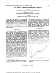
SHIH er al.: DESIGNING EM1 FILTERS FOR <strong>AC</strong> LINE APPLICATIONS 181<br />
Step I: Fig. 13(b) and (c) shows the base-line CM noise<br />
REFERENCES<br />
VCM and the base-line DM noise VDM of the tested circuit,<br />
respectively. Fig. 13(d) shows the total noise V T of ~ the ~<br />
tested circuit.<br />
Step 2: The CM attenuation requirement and the DM attenuation<br />
requirement are plotted in a log-log scale as shown<br />
in Fig. 14(a) and (b).<br />
[l] T. Guo, D. Chen, and F. C. Lee, “Separation of common-mode and<br />
~ differential-mode ~<br />
conducted EM1 noise,” in Proc. High Frequency<br />
Power Con$, Apr. 1994, San Jose, CA.<br />
[2] M. Nave, Power <strong>Line</strong> Filter Design <strong>for</strong> Switched Mode Power Supplies.<br />
Van Nostrand, 1991.<br />
[3] L. Schneider, “Noise source equivalent circuit model <strong>for</strong> off-line converters<br />
and its use in input filter design,” in Proc. ZEEE Symp., 1983,<br />
Step 3: From Fig.l4(a) and (b), fR,Cn/r = 14.6 kHz and<br />
fR,Dn/r = 13.0 kkh.<br />
Step 4a): Use C, = 3300 pF, then LC can be calculated<br />
from (1) as 18.0 mH. Choose a CM choke with LC = 20 mH.<br />
The leakage of the choke is about 240 mH from measurement.<br />
pp. 167-175.<br />
[4] D. Neufeldt, “Radiation masks conducted RFI power line filtering test,”<br />
EMC Technol. Mag., Apr.-Jun. 1984.<br />
[5] R. D. Middlebrook, “Input filter considerations in design and application<br />
of switching regulators,” in ZEEE Znd. Applicat. Soc. Annu. Meet. Rec.,<br />
1976, pp. 366-382.<br />
[6] F. S. Dos Reis, J. Sebastian, and J. Uceda, “Determination of EM1<br />
Step 4b): Using the leakage inductance (Lleakage =<br />
240pH) of the CM choke as LD and (3), CO, (= CXI =<br />
CX~) is calculated to be 0.625 pF, which is a practical value.<br />
So choose CDM = 0.68pF. Fig. 15 shows the test results<br />
when the filter was used. The results agree well with the theory<br />
emission in power factor preregulators by design,” in ZEEE PESC ’94,<br />
pp. 11 17-1 126.<br />
[7] T. F. Wu, K. Siri, and C. Q. Lee, “A systematic method in designing line<br />
filters <strong>for</strong> switching regulators,” in Proc. ZEEEAPEC ’92, pp. 179-185.<br />
[8] J. M. Simonelli and D. A. Torrey, “Input-filter design considerations <strong>for</strong><br />
boost-derived high power-factor converters,” in Proc. ZEEE APEC ’92,<br />
pp. 186-192.<br />
in the low-frequency range. To meet the high-frequency spec.,<br />
modification is needed, but no ef<strong>for</strong>t was made in this case<br />
to resolve the high-frequency problem because it is beyond<br />
[9] F. Lin and D. Y. Chen, “Reduction of power supply EM1 emission<br />
by switching frequency modulation,” in Proc. ZEEE PESC ’93, pp.<br />
127-133.<br />
[lo] P. Caldeira, R. Liu, D. Dalal, and W. J. Gu, “Comparison of EM1<br />
the scope of the paper.<br />
per<strong>for</strong>mance of PWM and resonant power converters,” in Proc. ZEEE<br />
PESC ’93, pp. 134-140.<br />
VI. CONCLUSION<br />
A practical procedure <strong>for</strong> designing the EM1 filter is pre-<br />
sented. This procedure leads to a quick filter design that at<br />
least meets the low-frequency part of design specification.<br />
Once designed and built, the filter may need slight modifica-<br />
tion to meet the high-frequency specification. This procedure<br />
facilitates the EM1 filter design process and greatly reduces<br />
cut-and-trial ef<strong>for</strong>t.<br />
A typical EM1 filter topology is used in the illustration in the<br />
paper, and the procedure has been experimentally verified in<br />
two switching power supply applications. The same procedure<br />
can be extended to other filter topologies, but this requires<br />
further work.<br />
Fu-Yuan Shih, <strong>for</strong> a photograph and biography, see this issue, p. 131.<br />
Dan Y. Chen (S’72-M’75-SM’83), <strong>for</strong> a photograph and biography, see this<br />
issue, p. 131.<br />
Yan-Pei Wu, <strong>for</strong> a photograph and biography, see this issue, p. 131.<br />
Yie-Tone Chen (S’91-M’94), <strong>for</strong> a photograph and biography, see this issue,<br />
p. 131.<br />
Authorized licensed use limited to: National Taiwan University. Downloaded on March 9, 2009 at 02:01 from IEEE Xplore. Restrictions apply.