Surgery and Healing in the Developing World - Dartmouth-Hitchcock
Surgery and Healing in the Developing World - Dartmouth-Hitchcock Surgery and Healing in the Developing World - Dartmouth-Hitchcock
10 80 Surgery and Healing in the Developing World cally manufactured batteries. More often than not, the clinic PV system will wind up using conventional thin-plate automotive batteries. This saves a lot of initial expense and is an easy way to proceed. However, the depth of cycling of the batteries must be carefully controlled. These cheap batteries can be expected to last only one year at the 20% discharge level, and maybe two years at the 10% discharge level, with temperature at 25˚C. Overall, the system is not as reliable as with the PV-dedicated batteries and has little autonomy. Regardless of the choice of battery, the single biggest cause of PV system failure is battery failure due to inadequate hydration. The battery is often the weak link in the PV chain. The user needs to be sure the system integrator has carefully explained exactly how the batteries are to be maintained. There are unfortunately many good PV arrays in developing countries that have been abandoned due to unnecessary battery failure. High temperature quickly degrades battery lifetime because of the accelerated plate corrosion. Keep the batteries in a cool enclosure (20˚-25˚C) and be sure to follow the manufacturer’s instructions for periodic hydration. A word of caution: the room or enclosure holding the batteries must have some ventilation. Toward the end of the charging phase, a flooded battery can produce an oxygen/hydrogen gas mixture. There is the potential for explosion or acid dispersal. Always use caution around batteries. Eye protection should be worn while servicing the battery bank. All PV systems are designed with some method for electrically isolating the battery from the array at night. This is necessary so that battery energy is not wasted by reverse flow of charge into the array when the sun goes down. Most systems allow the user to program disconnect/reconnect times into the charge controller. Other systems have a manual on/off switch. Both solar cells and PV modules have peculiar characteristics that are helpful to keep in mind when purchasing a system or when comparing one system against another. One such characteristic of all solar cells is the dependence of their power output with the load they are driving. That is, the power which is delivered into the electrical load (lighting, medical appliances, etc.) is dependent on the size of that load. (This is contrasted with internal combustion engines.) Figure 7 shows a pair of typical current vs voltage curves at the terminals of the array. The two curves correspond to different illumination levels. For each curve, there is a point near the knee of the curve that maximizes the product of current and voltage, i.e., maximizes the output power. This is called the maximum power point and is dependent only on the size of the load. The efficiency claimed by a module manufacturer, or by a system integrator for an entire system, is always in reference to the maximum power point of the module (or system). In this regard, efficiency claims always assume an optimal load. When a PV system is designed, the system integrator will configure the load so that the array stays near the maximum power point. On the module level, a curious characteristic is the dependence of power output on module obscuration. The output of a module is drastically degraded by partial shading. If even one cell in the module is completely shaded from the sun, the output of the module can fall immediately by as much as 80%. This phenomenon is reversible, and modern modules are expected to immediately regain full power output when the partial shading is removed. To assure optimal performance, though, it is important that all of the modules in an array receive full exposure during sunlight hours. Common sources of shading are trees, fence posts, and bird droppings. Heat build-up around an array also affects a PV system because of the degradation of solar cell output with increasing temperature. The temperature effect does
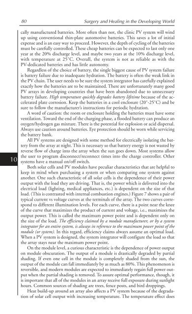
Establishing Electrical Power in Remote Facilities for Health Care 81 Figure 7. Current vs voltage curves for high and low illumination levels. The system is designed to operate near the maximum power point regardless of illumination level. no damage to the module, and it is completely reversible when the module cools down. But it should be avoided to optimize performance. With this in mind, it is important that modules not be mounted flush against a roof when deployed in a tropical location. Even if the ambient air is only 25˚C, the module can easily reach 60˚C due to absorption of the infrared part of the spectrum by the module back plane (usually rigid polyvinyl fluoride) and the roofing material. For a roof-mounted array, the installer will always allow at least 10 cm of ventilation space between the array and the roof. More frequently, an array will be mounted on angle iron or steel pipes that are fixed in concrete supports (Fig. 8). This assures stability in wind storms and allows for plenty of ventilation that will keep the array cool. Figure 8. Modules at a clinic in Sundarbans, West Bengal, India, are fixed to a frame and anchored in concrete. (Photo by J. Welch, courtesy NREL/PIX.) 10
- Page 46 and 47: 5 30 Surgery and Healing in the Dev
- Page 48 and 49: 5 32 Surgery and Healing in the Dev
- Page 50 and 51: 6 34 Surgery and Healing in the Dev
- Page 52 and 53: 6 36 Surgery and Healing in the Dev
- Page 54 and 55: 6 38 Surgery and Healing in the Dev
- Page 56 and 57: 6 40 Surgery and Healing in the Dev
- Page 58 and 59: 6 42 Surgery and Healing in the Dev
- Page 60 and 61: 6 44 Surgery and Healing in the Dev
- Page 62 and 63: 6 46 Surgery and Healing in the Dev
- Page 64 and 65: 6 48 Surgery and Healing in the Dev
- Page 66 and 67: 6 50 Surgery and Healing in the Dev
- Page 68 and 69: 6 52 Surgery and Healing in the Dev
- Page 70 and 71: 7 54 Surgery and Healing in the Dev
- Page 72 and 73: 7 56 Surgery and Healing in the Dev
- Page 74 and 75: 7 58 Surgery and Healing in the Dev
- Page 76 and 77: 8 60 Surgery and Healing in the Dev
- Page 78 and 79: 8 62 Surgery and Healing in the Dev
- Page 80 and 81: 8 64 Surgery and Healing in the Dev
- Page 82 and 83: 8 66 Surgery and Healing in the Dev
- Page 84 and 85: CHAPTER 9 Lab-in-a-Suitcase: Saving
- Page 86 and 87: 9 70 Surgery and Healing in the Dev
- Page 88 and 89: 10 72 Surgery and Healing in the De
- Page 90 and 91: 10 74 Surgery and Healing in the De
- Page 92 and 93: 10 76 Surgery and Healing in the De
- Page 94 and 95: 10 78 Surgery and Healing in the De
- Page 98 and 99: 10 82 Surgery and Healing in the De
- Page 100 and 101: 10 84 Surgery and Healing in the De
- Page 102 and 103: 10 86 Surgery and Healing in the De
- Page 104 and 105: 11 88 Surgery and Healing in the De
- Page 106 and 107: 11 90 Surgery and Healing in the De
- Page 108 and 109: CHAPTER 12 Communication in the Thi
- Page 110 and 111: 12 94 Surgery and Healing in the De
- Page 112 and 113: 12 96 Surgery and Healing in the De
- Page 114 and 115: CHAPTER 13 Anesthesia in the Third
- Page 116 and 117: 13 100 Surgery and Healing in the D
- Page 118 and 119: 13 102 Surgery and Healing in the D
- Page 120 and 121: 13 104 Surgery and Healing in the D
- Page 122 and 123: 13 106 Surgery and Healing in the D
- Page 124 and 125: 13 108 Surgery and Healing in the D
- Page 126 and 127: 14 110 Surgery and Healing in the D
- Page 128 and 129: 14 112 Surgery and Healing in the D
- Page 130 and 131: 14 114 Surgery and Healing in the D
- Page 132 and 133: 14 116 Surgery and Healing in the D
- Page 134 and 135: CHAPTER 15 Basic Obstetrics and Obs
- Page 136 and 137: 15 120 Surgery and Healing in the D
- Page 138 and 139: 15 122 Surgery and Healing in the D
- Page 140 and 141: 15 124 Surgery and Healing in the D
- Page 142 and 143: 15 126 Surgery and Healing in the D
- Page 144 and 145: 15 128 Surgery and Healing in the D
10<br />
80 <strong>Surgery</strong> <strong>and</strong> <strong>Heal<strong>in</strong>g</strong> <strong>in</strong> <strong>the</strong> Develop<strong>in</strong>g <strong>World</strong><br />
cally manufactured batteries. More often than not, <strong>the</strong> cl<strong>in</strong>ic PV system will w<strong>in</strong>d<br />
up us<strong>in</strong>g conventional th<strong>in</strong>-plate automotive batteries. This saves a lot of <strong>in</strong>itial<br />
expense <strong>and</strong> is an easy way to proceed. However, <strong>the</strong> depth of cycl<strong>in</strong>g of <strong>the</strong> batteries<br />
must be carefully controlled. These cheap batteries can be expected to last only one<br />
year at <strong>the</strong> 20% discharge level, <strong>and</strong> maybe two years at <strong>the</strong> 10% discharge level,<br />
with temperature at 25˚C. Overall, <strong>the</strong> system is not as reliable as with <strong>the</strong><br />
PV-dedicated batteries <strong>and</strong> has little autonomy.<br />
Regardless of <strong>the</strong> choice of battery, <strong>the</strong> s<strong>in</strong>gle biggest cause of PV system failure<br />
is battery failure due to <strong>in</strong>adequate hydration. The battery is often <strong>the</strong> weak l<strong>in</strong>k <strong>in</strong><br />
<strong>the</strong> PV cha<strong>in</strong>. The user needs to be sure <strong>the</strong> system <strong>in</strong>tegrator has carefully expla<strong>in</strong>ed<br />
exactly how <strong>the</strong> batteries are to be ma<strong>in</strong>ta<strong>in</strong>ed. There are unfortunately many good<br />
PV arrays <strong>in</strong> develop<strong>in</strong>g countries that have been ab<strong>and</strong>oned due to unnecessary<br />
battery failure. High temperature quickly degrades battery lifetime because of <strong>the</strong> accelerated<br />
plate corrosion. Keep <strong>the</strong> batteries <strong>in</strong> a cool enclosure (20˚-25˚C) <strong>and</strong> be<br />
sure to follow <strong>the</strong> manufacturer’s <strong>in</strong>structions for periodic hydration.<br />
A word of caution: <strong>the</strong> room or enclosure hold<strong>in</strong>g <strong>the</strong> batteries must have some<br />
ventilation. Toward <strong>the</strong> end of <strong>the</strong> charg<strong>in</strong>g phase, a flooded battery can produce an<br />
oxygen/hydrogen gas mixture. There is <strong>the</strong> potential for explosion or acid dispersal.<br />
Always use caution around batteries. Eye protection should be worn while servic<strong>in</strong>g<br />
<strong>the</strong> battery bank.<br />
All PV systems are designed with some method for electrically isolat<strong>in</strong>g <strong>the</strong> battery<br />
from <strong>the</strong> array at night. This is necessary so that battery energy is not wasted by<br />
reverse flow of charge <strong>in</strong>to <strong>the</strong> array when <strong>the</strong> sun goes down. Most systems allow<br />
<strong>the</strong> user to program disconnect/reconnect times <strong>in</strong>to <strong>the</strong> charge controller. O<strong>the</strong>r<br />
systems have a manual on/off switch.<br />
Both solar cells <strong>and</strong> PV modules have peculiar characteristics that are helpful to<br />
keep <strong>in</strong> m<strong>in</strong>d when purchas<strong>in</strong>g a system or when compar<strong>in</strong>g one system aga<strong>in</strong>st<br />
ano<strong>the</strong>r. One such characteristic of all solar cells is <strong>the</strong> dependence of <strong>the</strong>ir power<br />
output with <strong>the</strong> load <strong>the</strong>y are driv<strong>in</strong>g. That is, <strong>the</strong> power which is delivered <strong>in</strong>to <strong>the</strong><br />
electrical load (light<strong>in</strong>g, medical appliances, etc.) is dependent on <strong>the</strong> size of that<br />
load. (This is contrasted with <strong>in</strong>ternal combustion eng<strong>in</strong>es.) Figure 7 shows a pair of<br />
typical current vs voltage curves at <strong>the</strong> term<strong>in</strong>als of <strong>the</strong> array. The two curves correspond<br />
to different illum<strong>in</strong>ation levels. For each curve, <strong>the</strong>re is a po<strong>in</strong>t near <strong>the</strong> knee<br />
of <strong>the</strong> curve that maximizes <strong>the</strong> product of current <strong>and</strong> voltage, i.e., maximizes <strong>the</strong><br />
output power. This is called <strong>the</strong> maximum power po<strong>in</strong>t <strong>and</strong> is dependent only on<br />
<strong>the</strong> size of <strong>the</strong> load. The efficiency claimed by a module manufacturer, or by a system<br />
<strong>in</strong>tegrator for an entire system, is always <strong>in</strong> reference to <strong>the</strong> maximum power po<strong>in</strong>t of <strong>the</strong><br />
module (or system). In this regard, efficiency claims always assume an optimal load.<br />
When a PV system is designed, <strong>the</strong> system <strong>in</strong>tegrator will configure <strong>the</strong> load so that<br />
<strong>the</strong> array stays near <strong>the</strong> maximum power po<strong>in</strong>t.<br />
On <strong>the</strong> module level, a curious characteristic is <strong>the</strong> dependence of power output<br />
on module obscuration. The output of a module is drastically degraded by partial<br />
shad<strong>in</strong>g. If even one cell <strong>in</strong> <strong>the</strong> module is completely shaded from <strong>the</strong> sun, <strong>the</strong><br />
output of <strong>the</strong> module can fall immediately by as much as 80%. This phenomenon is<br />
reversible, <strong>and</strong> modern modules are expected to immediately rega<strong>in</strong> full power output<br />
when <strong>the</strong> partial shad<strong>in</strong>g is removed. To assure optimal performance, though, it<br />
is important that all of <strong>the</strong> modules <strong>in</strong> an array receive full exposure dur<strong>in</strong>g sunlight<br />
hours. Common sources of shad<strong>in</strong>g are trees, fence posts, <strong>and</strong> bird dropp<strong>in</strong>gs.<br />
Heat build-up around an array also affects a PV system because of <strong>the</strong> degradation<br />
of solar cell output with <strong>in</strong>creas<strong>in</strong>g temperature. The temperature effect does


