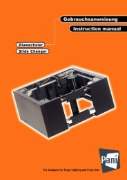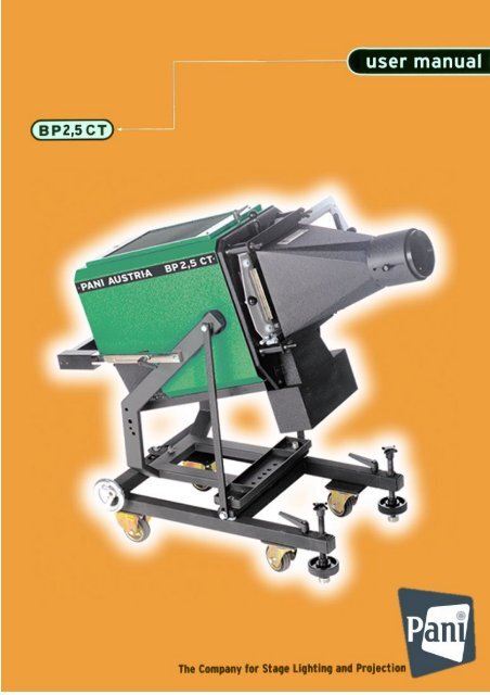
BP 2,5 CT (Turbo) Stage Projector - Pani Projection and Lighting
BP 2,5 CT (Turbo) Stage Projector - Pani Projection and Lighting
BP 2,5 CT (Turbo) Stage Projector - Pani Projection and Lighting

You also want an ePaper? Increase the reach of your titles
YUMPU automatically turns print PDFs into web optimized ePapers that Google loves.
<strong>Stage</strong> <strong>Projector</strong> <strong>BP</strong> 2,5 <strong>CT</strong><br />
Version December 2009<br />
<strong>Pani</strong> <strong>Projection</strong> <strong>and</strong> <strong>Lighting</strong> Vertriebs GmbH<br />
CONTENTS<br />
1) Dimension Drawing......................................................3<br />
1.1) <strong>Projector</strong>.................................................................3<br />
1.1.1) Yoke Assembly "St<strong>and</strong>ing"....................................3<br />
1.1.2) Yoke Assembly "Hanging".....................................3<br />
1.2) Ballast....................................................................3<br />
1.2.1) Type CBI................................................................3<br />
1.2.2) Type BC.................................................................3<br />
2) Position Drawing.......................................................4-7<br />
2.1) <strong>Projector</strong><br />
Legend for 2.1)......................................................4<br />
2.2) Control Panel on the <strong>Projector</strong><br />
Legend for 2.2)......................................................4<br />
2.3) Ballast<br />
2.3.1) Type CBI.............................................................5-6<br />
2.3.2) Type BC.................................................................7<br />
3) Mounting Accessories............................................8-10<br />
3.1) Undercarriage for<br />
<strong>Projector</strong>s of the "Compact"-Series.......................8<br />
3.2) Rolling Undercarriage for<br />
<strong>Projector</strong>s of the "Compact"-Series.......................8<br />
3.3) <strong>Projector</strong> Cart for<br />
<strong>Projector</strong>s of the "Compact"-Series.......................9<br />
3.4) Hanging Apparatus for<br />
<strong>Projector</strong>s of the "Compact"-Series.......................9<br />
3.5) 28mm DIN- Stud with<br />
Welded Mounting Plate.......................................10<br />
4) Construction..........................................................10-11<br />
4.1) Mechanical Construction of the <strong>Projector</strong>...........10<br />
4.2) Electrical Assembly of the <strong>Projector</strong>....................10<br />
4.3) Slide Carrier <strong>and</strong> Slide Cooling Fan....................10<br />
4.3.1) Electrical Connection of the<br />
Slide Cooling Ventilator Fan................................11<br />
4.3.2) Operating Mode "St<strong>and</strong>ard - Low Noise"............11<br />
5) Operating Tips.......................................................11-12<br />
5.1) HMI- Lamp.............................................................9<br />
5.1.1) Installation <strong>and</strong> Replacement<br />
of the HMI- Lamp...................................................9<br />
5.1.2) Lamp Adjustment............................................9+10<br />
5.2) Vertical Adjustment of the <strong>Projector</strong>....................10<br />
5.3) Yoke Assembly for<br />
St<strong>and</strong>ing or Hanging Configuration.....................10<br />
5.4) Using the Tilt Angle Meter...................................10<br />
2<br />
Page
<strong>Stage</strong> <strong>Projector</strong> <strong>BP</strong> 2,5 <strong>CT</strong><br />
<strong>Pani</strong> <strong>Projection</strong> <strong>and</strong> <strong>Lighting</strong> Vertriebs GmbH<br />
Page<br />
6) Position Drawing Condenser System......................13<br />
7) Electrical Connection...........................................13-14<br />
7.1) Main Connection..................................................13<br />
7.2) Connecting Cable Ballast – <strong>Projector</strong>.................13<br />
7.3) Remote Ignition - DMX 512................................14<br />
8) Objective Lenses........................................................14<br />
8.1) Front Condenser Lens.........................................14<br />
8.2) <strong>Projection</strong> Objective.............................................14<br />
8.3) Effect-<strong>and</strong> Varioobjective....................................14<br />
IMPORTANT REMARKS...................................14<br />
9) <strong>Projection</strong> Diagram....................................................15<br />
10) Slide (Transparency) Material...................................16<br />
11) Electrical Schematic (models of ballast: CBI <strong>and</strong> BC)..17-18<br />
12) Basic Unit as Delivered.............................................19<br />
13) Accessories...........................................................19-20<br />
14) General Technical Data.............................................21<br />
15) Spare Parts............................................................21-23<br />
PANI <strong>Projection</strong> <strong>and</strong> <strong>Lighting</strong> Vertriebs GmbH<br />
A – 1070 Wien, K<strong>and</strong>lgasse 23<br />
Austria, Europe<br />
Tel.: + 43 1 / 521 08 – 0<br />
Fax.: + 43 1 / 526 42 87<br />
E – mail: light@pani.com<br />
Internet: www.pani.com<br />
3
<strong>Stage</strong> <strong>Projector</strong> <strong>BP</strong> 2,5 <strong>CT</strong><br />
1) Dimension Drawing<br />
1.1) <strong>Projector</strong><br />
1.1.1) Mounting Yoke"St<strong>and</strong>ing"<br />
1.1.2) Mounting Yoke"Hanging"<br />
1.2) Ballast<br />
1.2.1) Type CBI 1.2.2) Type BC<br />
<strong>Pani</strong> <strong>Projection</strong> <strong>and</strong> <strong>Lighting</strong> Vertriebs GmbH<br />
4<br />
�� �� ��
<strong>Stage</strong> <strong>Projector</strong> <strong>BP</strong> 2,5 <strong>CT</strong><br />
2.1) <strong>Projector</strong><br />
Legend<br />
6 9 5 7<br />
12 3<br />
<strong>Pani</strong> <strong>Projection</strong> <strong>and</strong> <strong>Lighting</strong> Vertriebs GmbH<br />
2) Position Drawing<br />
(1) Adjustable Clamp Lever for Quick Adjust (On Both Sides)<br />
(2) H<strong>and</strong> Wheel for Fine Adjustment<br />
(3) Lamp Adjustment<br />
(4) Fastener for Housing Cover<br />
(5) Housing Cover<br />
(6) Objective Support Bolts<br />
(7) Telescoping Rails<br />
(8) Support Yoke<br />
(9) Adjustable Clamp Lever for Front Plate<br />
(10) Slide Carrier<br />
(11) Slide Carrier Locking Pin<br />
(12) Mode Switch "St<strong>and</strong>ard - Low Noise"<br />
(13) Ventilator Connector<br />
(14) Ventilator for Slide Cooling<br />
(15) Mounting Plate for Control Box G405/..<br />
2.2) Control Panel on the <strong>Projector</strong><br />
Legend<br />
(1) Power Indicator<br />
(2) ON- Push-button<br />
(3) OFF- Push-button<br />
(4) Elapsed Hour Counter<br />
(5) Ballast Connection<br />
(6) Outlets for auxilliary circuits<br />
(230 VAC) Amphenol 4-pole<br />
(7) Remote Ignition DMX 512<br />
2.3) Ballast<br />
2.3.1) Type CBI (new st<strong>and</strong>ard type)<br />
4<br />
5<br />
2<br />
13<br />
1<br />
15<br />
8<br />
11 10<br />
PANI AUSTRIA<br />
Type G503<br />
O.C. 12401<br />
14
<strong>Stage</strong> <strong>Projector</strong> <strong>BP</strong> 2,5 <strong>CT</strong><br />
Control Panel on the Ballast:<br />
<strong>Pani</strong> <strong>Projection</strong> <strong>and</strong> <strong>Lighting</strong> Vertriebs GmbH<br />
(1) ON- Push-button (green)<br />
Illuminated when power is connected to the ballast. When the "ON" - Push-button is<br />
momentarily pressed, the ignition cycle is activated <strong>and</strong> high voltage is applied to start<br />
the HMI lamp<br />
(2) OFF- Push-button (red)<br />
Lamp voltage is interrupted. It is recommended that the unit be allowed to cool down a<br />
few moments before re-ignition.<br />
ATTENTION: Re-ignition within 10 seconds of shut down is not possible because of<br />
circuit reasons!<br />
(3) Remote Switch (remote ignition)<br />
In switch position ON ignition is operated automatically , when power is applied (with<br />
operated main circuit braker 4).<br />
(4) Main Circuit Breaker<br />
2-pole Magnetic Circuit Breaker<br />
(5) Ground Test Indicator<br />
When depressed the indicator <strong>and</strong> correct polarity <strong>and</strong> grounding the orange indicating<br />
lamp glows orange.<br />
(8) Connector for connecting ballast cable<br />
10 4 3 2 1 5<br />
6<br />
9<br />
11<br />
12<br />
8<br />
13<br />
14<br />
15<br />
16
<strong>Stage</strong> <strong>Projector</strong> <strong>BP</strong> 2,5 <strong>CT</strong><br />
<strong>Pani</strong> <strong>Projection</strong> <strong>and</strong> <strong>Lighting</strong> Vertriebs GmbH<br />
(9) Voltage <strong>and</strong> Frequency Selector<br />
With this turn-switch, operating voltage <strong>and</strong> frequency may be chosen:<br />
240V/ 50 Hz 220V/ 50Hz <strong>and</strong> 220V/ 60Hz. (Ballast versions –A <strong>and</strong> –J have only<br />
frequency selector by a slide switch)<br />
(10) Main Connection Cable<br />
3x 2,5 mm², 2m long with Schuko- Connector<br />
(11) Shock Absorber<br />
4 rubber feet for vibration isolation<br />
Optional Operating Elements (DMX-Control) :<br />
(12) DMX ON/OFF Switch<br />
Activates the DMX – operation mode.<br />
(13) turn-switches for DMX – adress code<br />
Defines the adress for DMX – operation: from top to bottom:<br />
unit position<br />
decade position<br />
hundreds position<br />
(14) LED – indicators:<br />
top indicator green: Operation OK<br />
bottom indicator red: Fault<br />
(15) DMX - OUT<br />
DMX – output<br />
(16) DMX - IN<br />
DMX – Input<br />
Nonst<strong>and</strong>ard accessory for CBI-ballasts on dem<strong>and</strong>:<br />
Trolley<br />
(available in 2 versions, for<br />
transport of 2 or 4 ballasts<br />
together)<br />
Hanging on the hooks <strong>and</strong><br />
stacking the ballasts enables a<br />
fast, easy <strong>and</strong> stable kind of<br />
transport albeit over longer<br />
distances.<br />
7
<strong>Stage</strong> <strong>Projector</strong> <strong>BP</strong> 2,5 <strong>CT</strong><br />
2.3.1) Type BC<br />
(phased out model)<br />
Control Panel on<br />
the Ballast<br />
(1) Power indicator<br />
lamp<br />
Illuminated when power is connected to the ballast<br />
<strong>Pani</strong> <strong>Projection</strong> <strong>and</strong> <strong>Lighting</strong> Vertriebs GmbH<br />
(2) ON- Push-button (green)<br />
When the "ON" - Push-button is momentarily pressed, the<br />
ignition cycle is activated <strong>and</strong> high voltage is applied to start the HMI lamp<br />
(3) OFF- Push-button (red)<br />
Lamp voltage is interrupted. It is recommended that<br />
the unit be allowed to cool down a few moments before re-ignition<br />
ATTENTION: Re-ignition within 10 seconds of shut down is not possible.<br />
(4) Remote Switch (remote ignition)<br />
When the switch is rotated 90° clockwise<br />
(remote mode)ignition is automatic, when power is applied<br />
(5) Main Circuit Breaker<br />
2-pole Magnetic Circuit Breaker<br />
(6) Ground Test Indicator<br />
When depressed the indicator glows yellow indicating correct polarity <strong>and</strong><br />
grounding.<br />
(7) Low- Noise Switch<br />
In Low-Noise mode, silent ignition of the lamp is possible<br />
(8) Connector for connecting ballast cable<br />
(9) Voltage <strong>and</strong> Frequency Selector<br />
With the Main Selector switch, operating voltage <strong>and</strong> frequency may be chosen<br />
- 240V/ 50 Hz 220V/ 50Hz <strong>and</strong> 220V/ 60Hz. (only ballast BC2500-EP,<br />
frequency selector only for the other ballast versions)<br />
(10) Ground Indicator Lamp<br />
see No. 6.)<br />
3 4<br />
1 2 6 11 10<br />
�� �� ��<br />
(11) Main Connection Cable<br />
3x 2,5 mm 2 , 2m long with Schuko- Connector.<br />
7<br />
8<br />
5<br />
8<br />
9
<strong>Stage</strong> <strong>Projector</strong> <strong>BP</strong> 2,5 <strong>CT</strong><br />
<strong>Pani</strong> <strong>Projection</strong> <strong>and</strong> <strong>Lighting</strong> Vertriebs GmbH<br />
3) Mounting Accessories<br />
For st<strong>and</strong>ing <strong>and</strong> hanging projector installations, the following options are available.<br />
3.1) Undercarriage for <strong>Projector</strong>s of the "Compact"-Series<br />
Horizontal fine adjustment<br />
(+/-6°) <strong>and</strong> telescoping rails<br />
provide additional flexibility <strong>and</strong><br />
forward stabilization of the<br />
projector with the application of<br />
this accessory<br />
Order Code: 12036<br />
3.2) Rolling Undercarriage for <strong>Projector</strong>s of the<br />
"Compact"-Series<br />
Horizontal fine adjustment<br />
(+/-6°) <strong>and</strong> telescoping rails<br />
provide additional flexibility <strong>and</strong><br />
forward stabilization of the<br />
projector with the application of<br />
this accessory<br />
Order Code: 12001<br />
9
<strong>Stage</strong> <strong>Projector</strong> <strong>BP</strong> 2,5 <strong>CT</strong><br />
<strong>Pani</strong> <strong>Projection</strong> <strong>and</strong> <strong>Lighting</strong> Vertriebs GmbH<br />
3.3) <strong>Projector</strong> Cart for <strong>Projector</strong>s of the "Compact"-Series<br />
Rolling cart, with<br />
horizontal (±6°) <strong>and</strong><br />
associated vertical<br />
(+18° -20°) adjustment<br />
for projectors <strong>and</strong><br />
accessories<br />
(i.e. ZOOM - Objective).<br />
Order Code: 12037<br />
3.4) Hanging Apparatus for <strong>Projector</strong>s of the "Compact"-<br />
Series<br />
With horizontal positioning (±31°)<br />
<strong>and</strong> associated fine adjustment<br />
(±6°), for mounting on 2 pipes<br />
ø48mm.<br />
Order Code: 12038<br />
10
<strong>Stage</strong> <strong>Projector</strong> <strong>BP</strong> 2,5 <strong>CT</strong><br />
<strong>Pani</strong> <strong>Projection</strong> <strong>and</strong> <strong>Lighting</strong> Vertriebs GmbH<br />
3.5) 28mm DIN- Stud with Welded Mounting Plate<br />
Order Code: 12039<br />
4.1) Mechanical Construction of the <strong>Projector</strong><br />
The light sheet metal housing with double wall heat isolation system is mounted in a<br />
stable support yoke (8). Fine adjustment (2) is accomplished by means of adjustable<br />
telescoping rails on either side (7). The image plane with slide carrier can be rotated<br />
+/- 90° by losening the clamping lever (9) on the upper part of the housing. The 18x<br />
18 cm diapositives individually can be exactly adjusted with the aid of adjustment<br />
screws. The slide carrier is held in exact position by means of a spring loaded<br />
locking pin (11). By lifting the ball knob (11), the slide may be freely moved into the<br />
new position where it locks into position automatically.<br />
4.2) Electrical Assembly of the<strong>Projector</strong><br />
The complete electrical section is located in the black finished lower housing area; It<br />
is mounted to the green main housing with 4 screws.<br />
4.3) Slide Carrier <strong>and</strong> Slide Cooling Fan<br />
The slide cooling fan has two mounting configurations (It is mounted with 2 captured<br />
hex head screws- No. 4 hex wrench included):<br />
The upper position, closest to the slide, provides optimum cooling, the slide carrrier<br />
can however be rotated only +/- 6°.<br />
When choosing the lower position, the slide carrrier can be rotated ± 90°.<br />
ATTENTION: Slide cooling with the fan in the lower position is less efficient!<br />
POSITION NUMBERS SEE PAGE 4<br />
11
<strong>Stage</strong> <strong>Projector</strong> <strong>BP</strong> 2,5 <strong>CT</strong><br />
<strong>Pani</strong> <strong>Projection</strong> <strong>and</strong> <strong>Lighting</strong> Vertriebs GmbH<br />
4.3.1) Electrical Connection of the Slide Cooling Fan<br />
The electrical connection of the slide cooling fan is accomplished with a 5- pole<br />
connector, so that the fan housing can be removed from the projector both<br />
mechanically <strong>and</strong> electrically. 2 contacts in this connector are wire in such a way that<br />
when the connector is not plugged in the projector is shut down.<br />
4.3.2) Mode Switch "St<strong>and</strong>ard - Low Noise"<br />
A "St<strong>and</strong>ard - Low Noise" Mode switch is located on the slide cooling fan housing<br />
(12) (operated with a small screwdriver). ATTENTION: Use "Low- Noise" Mode only<br />
when silent operation is necessary, as cooling efficiency is reduced. Do not project<br />
dark slides or slides with large dark regions in this case.<br />
5.1 ) HMI- Lamp<br />
5) Operating Tips<br />
5.1.1) Lamp Installation <strong>and</strong> Replacement of the HMI- Lamp<br />
For operation of the <strong>Projector</strong> a single ended HMI- Lamp 2500 W is required. Order<br />
Code: 37202<br />
a) Disconnect the projector from the power source!<br />
b) Open the quick fastener (4) on the housing with a screw driver. Lift off the<br />
housing cover (5) <strong>and</strong> set it aside. A built in safety switch prevents an accidental<br />
operation of the unit when the housing is open.<br />
c) Lift out the reflector plate <strong>and</strong> reflector after removing the wing screw at the other<br />
end of the distance bar.<br />
d) Insert <strong>and</strong> / or replace the lamp.<br />
e) Replace the reflector into the slot of the bottom distance rods <strong>and</strong> tighten wing<br />
screw.<br />
f) Close the housing <strong>and</strong> lock the quick fastener.<br />
ATTENTION: Do not touch the quartz envelope of the lamp with your fingers during<br />
installation. Finger prints can be burned in !<br />
5.1.2) Lamp Adjustment<br />
Three (3) adjustment screws are located on der underside of the <strong>Projector</strong> for<br />
adjustment of the lamp.<br />
Each projector is carefully adjusted at the factory (lamp base, reflector <strong>and</strong><br />
condenser). With the high precision manufacturing of halogen lamps, adjustment of<br />
the lamp is rarely necessary. The HMI-lamp is supported at three points <strong>and</strong> can be<br />
brought into the desired position from the outside on the lower part of the projector<br />
with a three point adjustment. Proper adjustment of the lamp renders correct light<br />
distribution <strong>and</strong> color reproduction <strong>and</strong> prevents improper imaging.<br />
POSITION NUMBERS SEE PAGE 4<br />
12
<strong>Stage</strong> <strong>Projector</strong> <strong>BP</strong> 2,5 <strong>CT</strong><br />
<strong>Pani</strong> <strong>Projection</strong> <strong>and</strong> <strong>Lighting</strong> Vertriebs GmbH<br />
Following steps must be observed for adjustment of the lamp in this sequence:<br />
1) With the aid of adjustment screws (1) <strong>and</strong> (2) the height of the lamp is moved in<br />
relation to the optical axis.<br />
2) With the projector switched on, examine the light distribution. Adjust screws (1)<br />
<strong>and</strong> (2) accordingly.<br />
3) Color shift: If the lamp is too far from the mirror, a blue color shift will appear; if too<br />
close, a yellow shift will occur. Turn screw (3) until this effect disappears.<br />
Adjustment screw (1) (2) (3)<br />
Hexagonal key Nr. 4<br />
Screw (4) is adjusted at the factory<br />
DON´T TWIST!<br />
5.2) Vertical Adjustment of the <strong>Projector</strong><br />
a) Rough Positioning: For rough positioning, loosen the clamping lever on (1) both<br />
sides <strong>and</strong> move the projector to the desired position. Re–tighten the lever.<br />
b) Fine Adjustment: For fine adjustment of the projektor turn the star grip (2) <strong>and</strong><br />
bring the projector into the exact position.<br />
5.3) Yoke Assembly:„St<strong>and</strong>ing“ or „Hanging“ Configuration<br />
Separate the support yoke (8) (2 M 10 Nuts) <strong>and</strong> the telescope rails (7) on both sides<br />
from the projector; Turn the support yoke around 180° such that it is mounted again<br />
as a hanging yoke. Re-connect the telescoping<br />
rails.<br />
5.4) Using the Tilt Angle Meter<br />
For safe operation it is necessary to respect the tilt<br />
range of the projector (see General Technical Data<br />
on page 18).<br />
Use the delivered Tilt Angle Meter by applying it on<br />
the top edge of the projector (before operation). The<br />
red locator indicates the actual tilt angle.<br />
POSITION NUMBERS SEEPAGE 4<br />
13
<strong>Stage</strong> <strong>Projector</strong> <strong>BP</strong> 2,5 <strong>CT</strong><br />
<strong>Pani</strong> <strong>Projection</strong> <strong>and</strong> <strong>Lighting</strong> Vertriebs GmbH<br />
6) Position Drawing Condenser System<br />
Legend<br />
1 2 3 4 5 6<br />
Type: Order Code:<br />
(1) HPAL Mirror 89/160 100-15-70<br />
(2) HMI- Lamp 2500 W single ended H 1253 37202<br />
(3) Meniscus Lens Ø 140 mm 222- 03- 02 (4)<br />
Middle Condenser Lens PC Ø 220 mm/ R 157<br />
(5) PANI – Universal Filter Ø 220 x 4<br />
(6) Front Condenser Lens for Objective 11- 27 cm,<br />
PC Ø 230 mm, multicoated, with Mounting Plate 12440<br />
Front Condenser Lens for Objective 33- 40 cm,<br />
PC Ø 230 mm, multicoated, with Mounting Plate 12441<br />
Front Condenser Lens for Objective 50- 60cm,<br />
PC Ø 230 mm, multicoated, with Mounting Plate 12442<br />
Front Condenser Lens for Objective 80 -125 cm,<br />
PC Ø 230 mm, multicoated, with Mounting Plate 12443<br />
7) Electrical Connection<br />
(See Electrical Schematic 222 – 15 - 35 )<br />
The <strong>Stage</strong> <strong>Projector</strong> <strong>BP</strong> 2,5 <strong>CT</strong> is used in conjunction with the ballast BC 2500 W,<br />
220/240V - 50Hz, Current 16 A (Order Code: D 1525). The ballast incorporates a<br />
choke which limits lamp power to 25,6 A. Main power is interrupted when the<br />
projector housing is opened.<br />
7.1) Main Connection<br />
BC 2500 W, 220/240V - 50Hz<br />
Main Power Cable 3x2,5 square millimeters, two meters long with Schuko connector<br />
(black). Phase R: brown, Neutral N: blue, Ground: yellow/green<br />
Connected to power source 220VAC/50Hz. 16 A<br />
7.2) Connecting Cable Ballast - <strong>Projector</strong><br />
Between the ballast <strong>and</strong> projector is a 3x4 square mm + 4x1 square mm in a single<br />
cable. The st<strong>and</strong>ard length is 3 meters. This can be extended but must be tested if<br />
extremely long runs are required. The connection is made with connector bodies at<br />
both the ballast <strong>and</strong> projector end of the cable. The "ON" <strong>and</strong> the "OFF“ function<br />
can be performed at either the ballast or the projector. Thus, it is possible to locate<br />
the ballast away from the projector.<br />
14
<strong>Stage</strong> <strong>Projector</strong> <strong>BP</strong> 2,5 <strong>CT</strong><br />
7.3) Remote Ignition - DMX 512<br />
<strong>Pani</strong> <strong>Projection</strong> <strong>and</strong> <strong>Lighting</strong> Vertriebs GmbH<br />
For ignition <strong>and</strong> shut down of the projector by a DMX 512 signal, a relay card <strong>and</strong><br />
associated DMX In connector are located on the projector (Ignition Pos. 7). In<br />
addition the optional Universal DMX 512 interface <strong>and</strong> the corresponding ignition<br />
cable are necessary (for further information see the instruction manual of the<br />
Universal DMX 512 Interface).<br />
8) Objective Lenses<br />
8.1) Front Condenser Lens<br />
In the <strong>BP</strong> 2.5 <strong>CT</strong>, there are 4 different front condenser lenses to choose from,<br />
depending on the focal length objective lens required. These are as follows:<br />
PC Diameter 230 mm, multicoated<br />
for Objective Lens f= 11; 13,5; 18; 22 <strong>and</strong> 27 cm, Best. Nr.: 12440<br />
PC Diameter 230 mm, multicoated<br />
for Objective Lens f= 33 <strong>and</strong> 40 cm, Best. Nr.: 12441<br />
PC Diameter 230 mm, multicoated<br />
for Objective Lens f= 50 <strong>and</strong> 60 cm Best. Nr.: 12442<br />
PC Diameter 230 mm, multicoated<br />
for Objective Lens f= 80 cm <strong>and</strong> 125 cm Best. Nr.: 12443<br />
8.2) <strong>Projection</strong> Objective Lenses<br />
Optional projection objective lenses (focal lengths from f=11 to 80cm) <strong>and</strong> one<br />
ZOOM projections objective lens 25 – 60 cm are mounted on the four support bolts<br />
on the front of the projector. Each lens is fixed in place by four wing nuts. The focal<br />
length (f=) depends upon the projection distance <strong>and</strong> desired picture size. This is<br />
illustrated further with the aid of the projection diagram. Focus is achieved by sliding<br />
the objective lens forward or back along the optical axis. The focus position is fixed<br />
in place by two milled nuts located on either side of each objective lens.<br />
8.3) Effect- <strong>and</strong> Varioobjective Lenses<br />
To enhance the system of projection objective lenses, effects <strong>and</strong> vario-objective<br />
lenses are available. Effects Lenses (focal lengths of f=80/100 mm, 150 mm, 180<br />
mm, 250mm <strong>and</strong> 310 mm) provide a strong light output with good color correction,<br />
<strong>and</strong> may be used where an increase in depth or specific distortions are desired.<br />
With the aid of the vario-objective lenses [focal lengths of f=20-40 cm (motorized)<br />
<strong>and</strong> f=30-60 cm manual it is possible to enlarge or reduce image size. With the the<br />
f=20 – 40 cm / motorized it is possible to change the image size at different speeds.<br />
IMPORTANT REMARKS<br />
WHEN USING WIDE ANGLE LENSES (11-18cm):<br />
The projector must never be operated without a slide, with dimming shutters closed<br />
for longer than one minute!<br />
COMMON SAFETY REMARK:<br />
NEVER USE THE PROJE<strong>CT</strong>OR WITHOUT ANY OBJE<strong>CT</strong>IVE LENS,<br />
BECAUSE OF SAFETY REASONS !!!<br />
15
<strong>Stage</strong> <strong>Projector</strong> <strong>BP</strong> 2,5 <strong>CT</strong><br />
METER<br />
100<br />
90<br />
80<br />
70<br />
60<br />
50<br />
40<br />
30<br />
projection distance<br />
10 20<br />
5 10<br />
width of projection<br />
calculating formulas<br />
<strong>Pani</strong> <strong>Projection</strong> <strong>and</strong> <strong>Lighting</strong> Vertriebs GmbH<br />
9) <strong>Projection</strong> Diagram<br />
for O= 17cm<br />
F ... focal length of projection lens<br />
B ... width of the image<br />
D ... projection distance (measured from the middle of the objective lens)<br />
O ... object size (i.e. the used slide format)<br />
used slide format (O)= 17cm for glass slides<br />
15,5cm for filmholder<br />
125cm<br />
15<br />
16<br />
20<br />
80cm<br />
25<br />
60cm<br />
30<br />
50cm<br />
40cm<br />
33cm<br />
27cm<br />
25cm<br />
22cm<br />
18cm<br />
13,5cm<br />
11cm<br />
focal length<br />
F<br />
METER
<strong>Stage</strong> <strong>Projector</strong> <strong>BP</strong> 2,5 <strong>CT</strong><br />
<strong>Pani</strong> <strong>Projection</strong> <strong>and</strong> <strong>Lighting</strong> Vertriebs GmbH<br />
10) Slide (Transparency) Material<br />
Because of the ever changing available film materials, we do not wish to suggest any<br />
specific type. Our best recommendation however comes from our own experience<br />
with film type Duraclear (from Kodak) <strong>and</strong> type Ilfochrome (from Ilford). We can<br />
suggest that only professional photo labs who will care for your work be used. Not<br />
only for which development process is used but also the quality.<br />
Since short times also budget-priced ink jet printed foils are used to make slides.<br />
Please infourm yourself about actuals on our homepage ( www.pani.com ). In the<br />
download area you´ll find the latest information.<br />
Photographic transparencies should not be mounted between glass. The heat buildup<br />
will be such that the slides will be destroyed. Necessary cooling of photographic<br />
transparencies can only be guaranteed when using Special Slide Frames (Order<br />
code: 12802 for 18 x 18 cm).<br />
For simple <strong>and</strong> fast mounting in these frames we recommend the use of the Special<br />
Slide Punching Machine (Order code: 12801 for 18 x 18 cm slides).<br />
With h<strong>and</strong> painted slides, two glass plates are required such that the h<strong>and</strong> painted<br />
side is protected by a cover glass. An air gap of 1 mm is achieved by placing 4<br />
cardboard strips between the plates at the corners. The assembly is held together<br />
with two strips of tape as shown below.<br />
General remark:<br />
If possible, insert the slide with the layer averted from the projector to protect<br />
the layer!<br />
17
<strong>Stage</strong> <strong>Projector</strong> <strong>BP</strong> 2,5 <strong>CT</strong><br />
<strong>Pani</strong> <strong>Projection</strong> <strong>and</strong> <strong>Lighting</strong> Vertriebs GmbH<br />
11) Electrical Schematic<br />
<strong>BP</strong> 2,5 <strong>CT</strong> <strong>and</strong> ballast CBI 2500-E: Drawing No.: 222–15–36<br />
18
<strong>Stage</strong> <strong>Projector</strong> <strong>BP</strong> 2,5 <strong>CT</strong><br />
<strong>Pani</strong> <strong>Projection</strong> <strong>and</strong> <strong>Lighting</strong> Vertriebs GmbH<br />
<strong>BP</strong> 2,5 <strong>CT</strong> <strong>and</strong> ballast BC 2500 - E<br />
Drawing No.: 222 – 15 – 35<br />
19
<strong>Stage</strong> <strong>Projector</strong> <strong>BP</strong> 2,5 <strong>CT</strong><br />
<strong>Pani</strong> <strong>Projection</strong> <strong>and</strong> <strong>Lighting</strong> Vertriebs GmbH<br />
12) Basic Unit as Delivered<br />
1 HMI- STAGE PROJE<strong>CT</strong>OR 2,5 kW <strong>CT</strong><br />
The <strong>Projector</strong> is supplied with a universal mounting yoke for hanging <strong>and</strong><br />
st<strong>and</strong>ingconfigurations, includes 28 mm Stud with Mounting Plate.<br />
1 Ballast 2500 W, 220/ 240 V- 50 Hz,<br />
with 2 m mainconnection cable 3x 2,5 mm with Schuko connector, Type: D 1525<br />
3 m Connecting Cable between Ballast <strong>and</strong> <strong>Projector</strong>, Type: H 525<br />
1 Front Condenser Lens (as desired) for 11-27cm, 33-40cm, 50-60cm or 80-125cm<br />
1 Slide Carrier for 2 <strong>Projection</strong> slides 18x 18 cm<br />
1 Test slide with Raster on tempered glass 18x 18 cm Order Code: 12805<br />
1 Adjustable slide mask Order Code: 12019<br />
1 HMI- Lamp 2500 W/ 220 V<br />
single ended G 38 Order Code: 37202<br />
1 No. 4 Hex Wrench for Lamp Adjustment<br />
1 screened sketch block Type: G 1583<br />
1 "Dark" - Slide (for protection of dimming shutter) Type: G 1581<br />
1 Tilt Angle Meter<br />
1 User Manual<br />
1 <strong>Pani</strong> "Effects“ Brochure<br />
13) Accessories<br />
Description Type: Order Code:<br />
Interchangable Front Condenser Lens for Objective<br />
f = 11 cm to 27 cm, multicoated, Diameter 230 mm 12440<br />
Interchangable Front Condenser Lens for Objective<br />
f= 33 cm <strong>and</strong> 40 cm, multicoated, Diameter 230 mm 12441<br />
Interchangable Front Condenser Lens for Objective<br />
f= 50 cm <strong>and</strong> 60 cm, multicoated, Diameter 230 mm 12442<br />
Interchangable Front Condenser Lens for Objective<br />
f= 80 cm <strong>and</strong> 125cm, multicoated, Diameter 230 mm 12443<br />
HMI- Lamp 2500 W, single ended G 38 H 1253 37202<br />
Dimming Shutter/ PCS III<br />
with processor control for Gray Scale Glass<br />
20.5x 22 cm,incl. control box 120/ 220 V-50/60 Hz,<br />
external control 0 to +/-10 VDC <strong>and</strong> 120/ 220 VAC<br />
Dimmer output voltage, Dampening for smoothing of<br />
8 bit control voltage steps, selectable light linearity.<br />
incl. guide rails for use with objective lenses f= 11-27 cm G 405/PCS 22704<br />
Interchangeable guide rails 1 pair for use with objective<br />
Lenses f= 11-27 cm G 405/ 27 12011<br />
Interchangeable guide rails 1 pair for use with lens<br />
f= 33-40 cm, 80 cm, 125 cm <strong>and</strong> ZOOM 25-60cm G 405/ 40 12012<br />
Interchangeable guide rails<br />
1pair for use with objective lenses<br />
f= 50 cm <strong>and</strong> Vario-lens f= 20-40 cm G 405/ 50 12013<br />
Interchangeable guide rails<br />
1 pair for use with objective lenses<br />
f= 60 cm <strong>and</strong> Vario-lens f= 30-60 cm G 405/ 60 12014<br />
20
<strong>Stage</strong> <strong>Projector</strong> <strong>BP</strong> 2,5 <strong>CT</strong><br />
<strong>Pani</strong> <strong>Projection</strong> <strong>and</strong> <strong>Lighting</strong> Vertriebs GmbH<br />
Description Type: Order Code:<br />
Quick frames 18x18cm for film slides 12812<br />
Tool kit for Quick frames 12811<br />
Tempered glass plate 18x 18 cm G 502 12803<br />
Test slide with raster on Tempered glass 18x 18 cm G 506 12805<br />
Test Slide with Raster on Film, with Frame G 509<br />
Automatic Slide Changer- 32/ R<strong>and</strong>om Access AMD-32 12511<br />
Undercarriage for <strong>Projector</strong>s of the "Compact"-Series 12036<br />
Rolling Undercarriage for <strong>Projector</strong>s of the<br />
"Compact"-Series 12001<br />
<strong>Projector</strong> Cart for <strong>Projector</strong>s of the "Compact"-Series 12037<br />
Hanger for <strong>Projector</strong>s of the "Compact"-Series 12038<br />
28mm DIN-Stud with welded Mounting Plate 12039<br />
High Performance- Objective Lens<br />
f= 11 cm/ 1: 1,8 G 903 /II 12413<br />
High Performance- Objective Lens<br />
f= 13,5 cm/ 1: 1,8 G 904/ II 12414<br />
High Performance- Objective Lens<br />
f= 18 cm/ 1: 2,4 G 918/ II 12415<br />
<strong>Projection</strong> Objective Lens f= 22 cm/ 1: 2,8 G 907 12417<br />
<strong>Projection</strong> Objective Lens f= 27 cm/ 1: 3 G 908 12418<br />
<strong>Projection</strong> Objective Lens f= 33 cm/ 1: 3,6 G 909 12419<br />
<strong>Projection</strong> Objective Lens f= 40 cm/ 1: 3,6 G 910/ II 12420<br />
<strong>Projection</strong> Objective Lens f= 50 cm/ 1: 3,8 G 911/ II 12421<br />
<strong>Projection</strong> Objective Lens f= 60 cm/ 1: 3,8 G 912 12422<br />
<strong>Projection</strong> Objective Lens f= 80 cm/ 1: 4,5 G 913 12423<br />
<strong>Projection</strong> Objective Lens f= 125 cm/ 1: 7,6 G 914 12424<br />
ZOOM- Objective Lens 25- 60 cm/ 1: 2,7- 3,9<br />
Without Motor Drive 12433<br />
Effect Objective Lens f= 85/ 100 mm G 951 12426<br />
Effect Objective Lens f= 110 mm, Weitwinkel G 952 12427<br />
Effect Objective Lens f= 150 mm G 953 12428<br />
Effect Objective Lens f= 180 mm G 954 12429<br />
Effect Objective Lens f= 250 mm G 957 12430<br />
Effect Objective Lens f= 310 mm G 958 12431<br />
Effect Vario- Objective Lens f= 20- 40 cm-<br />
with motor drive 230 V, includes control box G 915 12432<br />
Effect Vario- Objective lens f= 30-60 cm-manual G 916 12425<br />
A wide range of effects devices can be seen in our "Effects" brocure<br />
21
<strong>Stage</strong> <strong>Projector</strong> <strong>BP</strong> 2,5 <strong>CT</strong><br />
<strong>Pani</strong> <strong>Projection</strong> <strong>and</strong> <strong>Lighting</strong> Vertriebs GmbH<br />
14) General Technical Data<br />
<strong>Projector</strong>:<br />
Tilt Angle Range of <strong>Projector</strong>:<br />
floor mounted: 22°up, 45°down<br />
hanging: 28°up, 39°down<br />
Protection Class: IP 20<br />
Max. Operating Temp. 35°C<br />
Weight:<br />
Unpacked<br />
Packed<br />
<strong>Projector</strong> 49 kg 73,5 kg<br />
Carton Dimensions: 80x70x90cm = 0,62m³<br />
Ballast (CBI) 28,5 kg 39,6 kg<br />
Carton Dimensions: 50x30x48cm = 0,72m³<br />
Ballast:<br />
Supply Voltage: 220/ 240 V- 50 Hz<br />
220 V- 60 Hz<br />
Current / Circuit Breaker 15 A / 16 A<br />
Lamp:<br />
Wattage 2500 W<br />
Rated Life 500 hrs.<br />
Color Temperature 6000 K<br />
Light Output 240 000 lm<br />
Lamp Voltage 115 V<br />
Lamp Current 25,6 A<br />
Lamp Base G 38<br />
Ignition Voltage 50 kV<br />
15) Spare Parts<br />
<strong>BP</strong> 2,5 <strong>CT</strong> Main Assy. No.: 222- 15<br />
Description<br />
Order Code:<br />
Housing Main Assy. No.: 222- 01-<br />
Qty./Unit<br />
Ball 65- 01- 18 3<br />
Springs for Lamp Adjustment 65- 01- 19 2<br />
Electro-mechanical Parts Main Assy. No.: 222- 02-<br />
Tangential Blower QLZ 06/1800- A18- 2513- 16 1<br />
Axial Blower Type 840. 110 2<br />
Annex Housing HB. 16. AG- VS 42. 50. 16. 000 1<br />
Pin Insert HSB 6/35 Sti. s HT 42. 10. 06. 62 1<br />
Elapsed Hour Counter A 1900 00005 A0 220V 50Hz 1<br />
Igniter AD 3050/B 1<br />
Cable for Igniter l=280 mm; l=460 mm Type 26 931 1x 4 ² ea 1x<br />
ON- Push-button (green) 1111 PF- B5 220V N/KV 1<br />
OFF- Push-button (red) 1105 PN- B5 220V N/KR 1<br />
Connector 31. 11. 000 1<br />
22
<strong>Stage</strong> <strong>Projector</strong> <strong>BP</strong> 2,5 <strong>CT</strong><br />
Description<br />
<strong>Pani</strong> <strong>Projection</strong> <strong>and</strong> <strong>Lighting</strong> Vertriebs GmbH<br />
Order Code:<br />
Optical Materials Main Assy. No.: 222- 03-<br />
Qty./Unit<br />
Plano Convex Lens for Objective 11- 27 cm Ø 230/ 300 SLC 1<br />
Plano Convex Lens for Objective 33- 40 cm Ø 230/ 360 SLC 1<br />
Plano Convex Lens for Objective 50- 60 cm Ø 230/ 390 SLC 1<br />
Plano Convex Lens for Objective 80-125 cm Ø 230/ 500 SLC 1<br />
Plano Convex Lens (middlelens) Ø 220/ 300 SLC(2) 1<br />
Meniscus Lens ∅ 147mm 222 - 03 - 05 1<br />
PANI – universal filter Ø220 1<br />
HPAL Mirror 89/160 100 - 15 - 70 1<br />
Mechanical Material Main Assy. No.: 222- 04-<br />
H<strong>and</strong> Wheel DIN 950 Al 80 B12A black anodized 1<br />
Plastic Clamping Lever GN 500 42 M6 sw 1<br />
Adjustable Clamping Lever GN 300 63 M8 12 sw 2<br />
Wing Nut M 8; DIN 315 4<br />
Safety Switch complete 68- 36- 1<br />
Undercarriage Main Assy. No.: 222- 07-<br />
Pull Out 222- 07- 03/a 2<br />
Support Bracket 222- 07- 04 1<br />
Overlay for Support Bracket PN 1030 2<br />
Lift off Spindle 222- 07- 13 2<br />
Pressure Piece DIN 6311- 20- S 2<br />
PVC Sleeve Black 35x 35 Nr. 218-0035/037/27 2<br />
PVC Sleeve Black 40x 40 Nr. 218-0040/040/27 2<br />
Rolling Undercarriage Main Assy. No.: 230- 06-<br />
Pull Out 230- 05- 02 1<br />
Support Bracket 222- 07- 04 1<br />
Overlay for Support Bracket PN 1030 2<br />
Lift off Spindle 68- 28- 04 a 2<br />
Pressure Piece DIN 6311- 20- S 2<br />
Casters CD 80 CB 2<br />
Wheels CDF 80 CB 2<br />
PVC Sleeve Black 35x 35 Nr. 218-0035/037/27 2<br />
PVC Sleeve Black 40x 40 Nr. 218-0040/040/27 2<br />
<strong>Projector</strong> Cart Main Assy. No.: 240- 01-<br />
Strap Cover 240- 01- 16/a 1<br />
Strap 16 T5/ 455 1<br />
Casters 441i 08 R 100C ZPI 2<br />
Wheels 439a 08 R 100C ZPI 2<br />
Hanger for <strong>Projector</strong> Main Assy. No.: 242- 02- complete<br />
28mm DIN-Stud with<br />
welded Mounting Plate Main Assy. No.: 65- 04- 11 complete<br />
Ballast BC 2500- EP (phased out model)<br />
23
<strong>Stage</strong> <strong>Projector</strong> <strong>BP</strong> 2,5 <strong>CT</strong><br />
<strong>Pani</strong> <strong>Projection</strong> <strong>and</strong> <strong>Lighting</strong> Vertriebs GmbH<br />
For spareparts of the ballast versions -A <strong>and</strong> -J <strong>and</strong> for all parts of the ballast CBI<br />
2500-E please contact the PANI-support team!<br />
Description Order Code: Pos. Qty. / Unit<br />
Housing 71111507 1 1<br />
Capacitor Box 71104763 2 1<br />
Base Plate 71115311 3 1<br />
Front Panel 71011955 4 1<br />
Connector Plate 81014176 5 1<br />
Cable Clamp 87534075 7 1<br />
Power Cable 93643016 8 1<br />
Clamp 84620063 9 1<br />
Guard 88471122 11 1<br />
Circuit Breaker 88502132 12 1<br />
Grounding Clamp 84610156 13 1<br />
Resistor 88205275 15 1<br />
Capacitor 88320030 16 5<br />
Choke 63090152 17 1<br />
Printed Circuit Board 78800550 18 1<br />
Push Switch 88901500 20 1<br />
Output Coupling (complete) 97000170 21 1<br />
Circuit Breaker Frame 87435204 22 1<br />
Frame with Push-button 74140003 23 1<br />
Voltage Selector Switch 88430122 25 1<br />
Voltage Selector Switch 87444276 27 1<br />
Shock Mounts H 25 88941400 29 2<br />
Shock Mounts H 15 88941401 30 4<br />
Feet 87330020 31 4<br />
24